EP0507508B1 - Polarisationsmultiplexierung mit solitons - Google Patents
Polarisationsmultiplexierung mit solitons Download PDFInfo
- Publication number
- EP0507508B1 EP0507508B1 EP92302643A EP92302643A EP0507508B1 EP 0507508 B1 EP0507508 B1 EP 0507508B1 EP 92302643 A EP92302643 A EP 92302643A EP 92302643 A EP92302643 A EP 92302643A EP 0507508 B1 EP0507508 B1 EP 0507508B1
- Authority
- EP
- European Patent Office
- Prior art keywords
- stream
- polarization
- pulse
- pulse streams
- soliton pulses
- Prior art date
- Legal status (The legal status is an assumption and is not a legal conclusion. Google has not performed a legal analysis and makes no representation as to the accuracy of the status listed.)
- Expired - Lifetime
Links
Images


Classifications
-
- G—PHYSICS
- G02—OPTICS
- G02B—OPTICAL ELEMENTS, SYSTEMS OR APPARATUS
- G02B6/00—Light guides; Structural details of arrangements comprising light guides and other optical elements, e.g. couplings
- G02B6/24—Coupling light guides
- G02B6/26—Optical coupling means
- G02B6/27—Optical coupling means with polarisation selective and adjusting means
- G02B6/2706—Optical coupling means with polarisation selective and adjusting means as bulk elements, i.e. free space arrangements external to a light guide, e.g. polarising beam splitters
- G02B6/2713—Optical coupling means with polarisation selective and adjusting means as bulk elements, i.e. free space arrangements external to a light guide, e.g. polarising beam splitters cascade of polarisation selective or adjusting operations
- G02B6/272—Optical coupling means with polarisation selective and adjusting means as bulk elements, i.e. free space arrangements external to a light guide, e.g. polarising beam splitters cascade of polarisation selective or adjusting operations comprising polarisation means for beam splitting and combining
-
- G—PHYSICS
- G02—OPTICS
- G02B—OPTICAL ELEMENTS, SYSTEMS OR APPARATUS
- G02B6/00—Light guides; Structural details of arrangements comprising light guides and other optical elements, e.g. couplings
- G02B6/24—Coupling light guides
- G02B6/26—Optical coupling means
- G02B6/27—Optical coupling means with polarisation selective and adjusting means
- G02B6/2753—Optical coupling means with polarisation selective and adjusting means characterised by their function or use, i.e. of the complete device
- G02B6/2773—Polarisation splitting or combining
-
- H—ELECTRICITY
- H04—ELECTRIC COMMUNICATION TECHNIQUE
- H04B—TRANSMISSION
- H04B10/00—Transmission systems employing electromagnetic waves other than radio-waves, e.g. infrared, visible or ultraviolet light, or employing corpuscular radiation, e.g. quantum communication
- H04B10/25—Arrangements specific to fibre transmission
- H04B10/2507—Arrangements specific to fibre transmission for the reduction or elimination of distortion or dispersion
- H04B10/25077—Arrangements specific to fibre transmission for the reduction or elimination of distortion or dispersion using soliton propagation
-
- H—ELECTRICITY
- H04—ELECTRIC COMMUNICATION TECHNIQUE
- H04J—MULTIPLEX COMMUNICATION
- H04J14/00—Optical multiplex systems
- H04J14/06—Polarisation multiplex systems
-
- H—ELECTRICITY
- H04—ELECTRIC COMMUNICATION TECHNIQUE
- H04J—MULTIPLEX COMMUNICATION
- H04J14/00—Optical multiplex systems
- H04J14/08—Time-division multiplex systems
Definitions
- This invention relates generally to optical communications and in particular to multiplexed communications using solitons.
- a pulse's history can be modified by two things: (1) changes in the birefringence of the fiber segments making up the system, and (2) the spontaneous emission noise (ASE) that is superimposed at random on the individual pulses.
- the former changes tend to be on a very slow time scale (typically minutes or longer), so that they are easily compensated by an automatic polarization controller device at the output of the system.
- an automatic polarization controller device at the output of the system.
- an optical communication system characterized by:
- the invention also extends to a transmitter for use in an optical communication system, characterized by a single signal source for generating a stream of soliton pulses; a signal splitter for splitting the generated stream of soliton pulses into a plurality of individual pulse streams, each pulse stream having a different polarization; a modulator for modulating each pulse stream with information to be transmitted; and a multiplexer for time and polarization interleaving the modulated pulse streams to obtain a multiplexed stream of soliton pulses and launching the multiplexed stream onto a transmission line, said transmission line having a relatively low polarization dependence as characterized by, for any two polarizations, a relatively small difference in system gain and a relatively small time delay compared to a bit period.
- the invention further extends to a method of transmitting information in an optical communication system, characterized by the steps of:
- the present invention which utilises a combination of polarisation and time division multiplexing in a soliton communication system, is based on the fact that solitons typically occupy only a small fraction ( ⁇ 20%) of the bit period, so that several streams of pulses carrying information from independent sources can be interleaved in time and multiplexed with different polarisations.
- polarization separation can be performed on a received signal, as has been confirmed experimentally and theoretically. This is described in more detail below.
- ⁇ T time delay difference
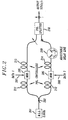
- the signal source for the two channels is a single, mode-locked laser 201, producing -35-50 ps wide soliton pulses at a 2.5 GHz rate. Its output is split into two soliton pulse streams having essentially orthogonal polarizations, in a splitter 202, and each half separately modulated (with different information bearing signals labeled Data 1 and Data 2) in modulators 205 and 206.
- Modulator 205 receives a first information bearing signal or data stream on line 207, while modulator 206 receives a second data stream on line 208.
- the two soliton pulse streams then recombine in a splitter 210, but only after one of the pulse streams is delayed by one-half of the 2.5Gbits/s bit period in an adjustable delay line 209 so that the two pulse streams are interleaved in time.
- the modulators 205, 206 should preferably be of the LiNbO 3 , balanced Mach-Zehnder type, as those produce virtually no chirping of the soliton pulses, and have an adequate on-off ratio ( ⁇ 20 dB).
- the required linear polarizations at the inputs to modulators 205, 206, and for the polarization multiplexing itself, can either be maintained through the use of (linear) polarization-preserving fiber throughout the multiplexer, or through the use of polarization controllers, such as controllers 211-214, both before and after modulators 205,206 as shown in Fig. 2.
- Polarization controllers 211-214 may be arranged as described in an article by H.C.Levevre, "Single-Mode Fiber Fractional Wave Devices and Polarization Controllers", Electronics Letters, Vol. 16, p. 778, 1980.
- adjustable delay line 209 which is shown interposed between the output of modulator 206 and polarization splitter 210. Nevertheless, delay line 209 is not absolutely necessary. It is also possible to trim the length of one or the other arm, through one or two trials, to within a few picoseconds of the correct length so the apparatus may remain all-waveguide throughout.
- soliton pulse stream output from the correctly adjusted multiplexer of Fig. 2 would appear as shown in Fig. 3.
- the field envelopes along the x and y axes represent pulses of different (orthogonal) polarizations.
- soliton pulses 301 and 302 have an initial polarization along the axis and a period of 400 ps.
- Soliton pulses 303 and 304 have an orthogonal (y direction) polarization, the same period, and are time interleaved with the first series of pulses.
- Information is carried in the pulse streams by virtue of the presence or absence of pulses at the expected or nominal positions on the time axis. Note that launching the soliton pulses as in Fig. 3 not only achieves the potential for combined time and polarization division demultiplexing at the receiving end, but also virtually eliminates the potential for cross-phase modulation, and hence virtually eliminates the potential for interaction during transmission, between the two channels.
- a sample of the output pulse stream can be taken, with the two polarization components equally weighted, so that either its optical spectrum, or the microwave spectrum of the detected sample can be observed.
- the randomly modulated pulse stream will exhibit a line spectrum whose components are separated by multiples of 2.5 GHz.
- the odd harmonics of 2.5 GHz will disappear, leaving only components spaced by multiples of 5 GHz.
- the simplest device to check on the temporal adjustment could be made from a detector and a simple resonant circuit tuned to 2.5 GHz.
- the transmission line itself must meet two requirements for successful polarization division multiplexing/demultiplexing.
- the first requirement can be met by using completely non-polarizing wavelength division multiplexing (WDM) couplers for pump injection (such as those made by JDS Optics, which use essentially normal incidence reflection from interference filters), and by keeping all other potentially polarizing components to a minimum.
- WDM wavelength division multiplexing
- Such polarization independent gain has been achieved in a recirculating loop which contained nothing but dispersion shifted and amplifier fibers, JDS couplers, a non-polarizing fiber-fusion coupler for input/output, and one nearly non-polarizing isolator.
- the second requirement is easily met with presently available dispersion shifted fibers, for which the polarization dispersion parameter ( ⁇ /h 1/2 ) is now typically ⁇ 0.2 ps/nm/km, so that ⁇ T 2 ⁇ ⁇ 20 ps or less, even for the greatest system length ( ⁇ 10,000 km).
- the emerging, and arbitrary, states of polarization must be transformed so that the unwanted channel in each arm of the demultiplexer can be optimally rejected by a linear polarization analyzer.
- This transformation may be done with the electrically driven and continuously adjustable polarization controller of the kind recently built and tested by F. Heismann et al., as described in Electronics Letters, Vol. 27, No. 4, February 1991, p. 377-79.
- the overall gains for orthogonal polarizations are substantially equal, the polarizations for the two channels would remain orthogonal throughout. In that event, one polarization controller would be required, and could transform the data streams into two orthogonal linear polarizations.
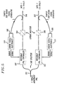
- the demultiplexer could then be arranged as shown in Fig. 4.
- the received multiplexed signal on input 401 is a 5 Gbits/s stream of pulses with arbitrary polarization.
- This input is applied to a Heismann polarization controller 402, which can transform an arbitrary and varying input state of polarization into any desired specific output state of polarization.
- This transformation can be used to change the polarization state of the incoming 5 Gbits/s data stream into a state (e.g., linear polarization) which allows separation into two 2.5 Gbits/s pulse streams on outputs 405 and 406, using only a polarization splitter 404.
- the pulse stream on output 405 is modulated by one of the information bearing signals, Data 1, while the pulse stream on output 406 is modulated by the other information bearing signal, Data 2.
- a portion of the signal on output 406 is fed back to controller 402 via a detector 408 and error signal electronics 410, which includes a 2.5 GHz microwave resonant filter that generates an error signal necessary for the controller 402 to track and correct for the slow variations in the polarization state of the incoming 5 Gbits/s pulse stream.
- error signal electronics 410 which includes a 2.5 GHz microwave resonant filter that generates an error signal necessary for the controller 402 to track and correct for the slow variations in the polarization state of the incoming 5 Gbits/s pulse stream.
- a non-polarizing 3 dB splitter 501 is used to split the input pulse stream and apply a (generally equal) portion to each of two similar Heismann polarization controllers 502 and 503.
- the output of each controller is applied to a respective linear analyzer 504, 505, which nulls out the unwanted channel in each arm by making its polarization linear and orthogonal to the output from controller 502 or 503.
- Data 1 is thus recovered on output 506, while data 2 is recovered on output 507.
- each polarization controller 502, 503 To generate an error signal for each polarization controller 502, 503, the technique described above in conjunction with Fig. 4 may be used. Thus, a sample of the 2.5 Gbits/s stream from each output 506, 507 of the demultiplexer is applied to a respective detector 508, 509 and passed through a corresponding 2.5 GHz microwave resonant filter 510, 511. Both polarization controllers 502, 503 are adjusted for maximum signal. (For perfectly orthogonal channels, as in Fig. 4, this need be done for only one arm.) To remain locked on to the maximum, as is well-known and has been demonstrated by Heismann in the above-cited reference, it may sometimes be necessary to dither one element of the polarization controller and to use phase sensitive detection to derive the appropriate error signal.
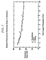
- ⁇ is the standard deviation of the timing jitter described by J. P. Gordon and H. A. Haus, "Random Walk of Coherently Amplified Solitons in Optical Fiber Transmission," Opt. Lett. 11, pp. 665-667, Oct. 1986, then the probability that the unwanted pulses would lie outside that zone would be ⁇ 10 -3 . Since a typical value for ⁇ , given reasonable assumptions about the amplifier spacings and noise figures, is about 13 ps at 9000 km, about 80 ps in total would be eliminated from the normal 400 ps bit period.
- the Gordon-Haus jitter requires a total width of about 2 ⁇ 7 ⁇ , or about 180-200 ps in this case.
- the 320 ps capture zone 604, 605 would allow a large safety margin for the net 5 Gbits/s single-wavelength rate.
- One could, in fact, have a single-wavelength rate closer to 7.5 Gbits/s (two 3.75 Gbits/s channels multiplexed overall together. This would have adequately large, 267-80 187 ps effective capture window).
- the technique described here should allow one to double, or at least nearly double the single-wavelength capacity of an ultra-long-distance soliton transmission system.
Claims (8)
- Optisches Kommunikationssystem, gekennzeichnet durch:einen Transmitter, wobei der Transmitter beinhaltet
eine einzelne Signalquelle (201) zur Erzeugung eines Stromes aus Soliton-Pulsen;
einen Signalsplitter (202) zum Splitten des erzeugten Stromes aus Soliton-Pulsen in eine Mehrzahl von einzelnen Pulsströmen, wobei jeder Pulsstrom eine unterschiedliche Polarisation aufweist;
einen Modulator (205,206) zum Modulieren jedes Pulsstromes mit zu übertragender Information; und
einen Multiplexer (beispielsweise 209-214) zum Zeit- und Polarisationsverschachteln der modulierten Pulsströme, um einen gemultiplexten Strom aus Soliton-Pulsen zu erhalten und den gemultiplexten Strom auf eine Übertragungsleitung zu geben;
eine Übertragungsleitung mit einer relativ geringen Polarisationsabhängigkeit, gekennzeichnet durch, für jede zwei Polarisationen, eine relativ kleine Differenz in der Systemverstärkung und eine relativ geringe Zeitverzögerung, im Vergleich zu einer Bitperiode; undeinen Empfänger, wobei das Empfangen beinhaltet
einen Demultiplexer (beispielsweise 404-406) zum Separieren der modulierten Pulsströme nach einer Übertragung über der Übertragungsleitung; und
einen Demodulator zum Demodulieren jedes empfangenen Pulsstromes zur Wiedergewinnung der darauf modulierten Information. - Transmitter zur Verwendung in einem optischen Kommunikationssystem, gekennzeichnet durch:eine einzelne Signalquelle (201) zur Erzeugung eines Stromes aus Soliton-Pulsen;einen Signalsplitter (202) zum Splitten des erzeugten Stroms aus Soliton-Pulsen in eine Mehrzahl von einzelnen Pulsströmen, wobei jeder Pulsstrom eine unterschiedliche Polarisation aufweist;einen Modulator (205,206) zum Modulieren jedes Pulsstromes mit zu übertragender Information; undeinen Multiplexer (beispielsweise 209-214) zum Zeit- und Polarisationsverschachteln der modulierten Pulsströme, um einen gemultiplexten Strom aus Soliton-Pulsen zu erhalten und den gemultiplexten Strom auf eine Übertragungsleitung zu geben, wobei die Übertragungsleitung eine relativ geringe Polarisationsabhängigkeit aufweist, die dadurch gekennzeichnet ist, daß für jede zwei Polarisationen eine relativ kleine Differenz in der Systemverstärkung und eine relativ geringe Zeitverzögerung im Vergleich zu einer Bitperiode auftritt.
- Transmitter nach Anspruch 2, weiterhin dadurch gekennzeichnet, daß einzelne Pulsströme im wesentlichen eine orthogonale Polarisation aufweisen.
- Transmitter nach Anspruch 3, weiterhin dadurch gekennzeichnet, daß der Multiplexer einen Polarisationssplitter (210) zum Kombinieren eines ersten Puls-Stromes aus den einzelnen Pulsströmen mit einem verzögerten zweiten Pulsstrom aus den einzelnen Pulsströmen aufweist, um dadurch den gemultiplexten Strom aus Soliton-Pulsen zu erhalten.
- Transmitter nach Anspruch 4, weiterhin dadurch gekennzeichnet, daß der Multiplexer eine einstellbare Verzögerungsleitung (209) zum Erhalten einer gewünschten Zeitverzögerung (dt) zwischen einem ersten Pulsstrom aus den einzelnen Pulsströmen und einem zweiten Pulsstrom aus den einzelnen Pulsströmen aufweist.
- Verfahren zum Transmittieren von Informationen in einem optischen Kommunikationssystem, gekennzeichnet durch die folgenden Schritte:Erzeugen eines Stroms aus Soliton-Pulsen mit einer einzelnen Signalquelle (201);Splitten des erzeugten Stroms aus Solitonpulsen in eine Mehrzahl von einzelnen Pulsströmen, wobei jeder Pulsstrom eine unterschiedliche Polarisation aufweist;Modulation jedes Pulsstroms mit zu einem entfernten Empfänger zu übertragender Information;Zeit- und Polarisationsverschachteln der modulierten Pulsströme, um einen gemultiplexten Strom aus Soliton-Pulsen zu erhalten; undAufbringen des gemultiplexten Stroms auf eine Übertragungsleitung mit einer relativ geringen Polarisationsabhängigkeit, die dadurch gekennzeichnet ist, daß für jede zwei Polarisationen eine relativ geringe Differenz in der Systemverstärkung und eine relativ geringe Zeitverzögerung im Vergleich zu einer Bitperiode auftritt.
- Verfahren nach Anspruch 6, weiterhin dadurch gekennzeichnet, daß erste und zweite Pulsströme mit im wesentlich orthogonalen Polarisationen während des Splittingschrittes erhalten werden.
- Verfahren nach Anspruch 6, weiterhin dadurch gekennzeichnet, daß der Verschachtelungsschritt das Einstellen einer Zeitverzögerung zwischen den ersten und zweiten Pulsströmen beinhaltet und anschließend diese in einem Polarisationssplitter kombiniert werden.
Applications Claiming Priority (2)
| Application Number | Priority Date | Filing Date | Title |
|---|---|---|---|
| US680456 | 1991-04-04 | ||
| US07/680,456 US5111322A (en) | 1991-04-04 | 1991-04-04 | Polarization multiplexing device with solitons and method using same |
Publications (3)
| Publication Number | Publication Date |
|---|---|
| EP0507508A2 EP0507508A2 (de) | 1992-10-07 |
| EP0507508A3 EP0507508A3 (de) | 1994-01-19 |
| EP0507508B1 true EP0507508B1 (de) | 2003-08-13 |
Family
ID=24731193
Family Applications (1)
| Application Number | Title | Priority Date | Filing Date |
|---|---|---|---|
| EP92302643A Expired - Lifetime EP0507508B1 (de) | 1991-04-04 | 1992-03-26 | Polarisationsmultiplexierung mit solitons |
Country Status (5)
| Country | Link |
|---|---|
| US (1) | US5111322A (de) |
| EP (1) | EP0507508B1 (de) |
| JP (1) | JP2828369B2 (de) |
| AU (1) | AU639177B2 (de) |
| DE (1) | DE69233151T2 (de) |
Families Citing this family (94)
| Publication number | Priority date | Publication date | Assignee | Title |
|---|---|---|---|---|
| US5150248A (en) * | 1989-07-21 | 1992-09-22 | Alfano Robert R | Terahertz repetition rate optical computing systems, and communication systems and logic elements using cross-phase modulation based optical processors |
| US5265112A (en) * | 1991-09-27 | 1993-11-23 | Siemens Aktiengesellschaft | Optical comb generator |
| JP2711773B2 (ja) * | 1992-02-03 | 1998-02-10 | 国際電信電話株式会社 | 光波形整形装置 |
| US5502588A (en) * | 1992-06-24 | 1996-03-26 | France Telecom | Optical transmission process and system for sending solitons over very long distances |
| JP2739813B2 (ja) * | 1993-12-20 | 1998-04-15 | 日本電気株式会社 | 偏波分散補償方法 |
| FR2719957B1 (fr) * | 1994-05-11 | 1996-08-09 | France Telecom | Procédé pour la transmission d'informations codées sous forme binaire par un train de solitons. |
| EP0723168A3 (de) * | 1995-01-23 | 1998-07-15 | Siemens Aktiengesellschaft | Einstellbare optische Verzögerungsleitung |
| GB2298751B (en) * | 1995-03-04 | 1999-01-27 | Northern Telecom Ltd | Conditioning solitons |
| US5610746A (en) * | 1995-09-29 | 1997-03-11 | Ranalli; Eliseo R. | Programmable switched delay encoder |
| FR2742887B1 (fr) * | 1995-12-21 | 1998-01-16 | Alcatel Submarcom | Modulateur optique reglable d'amplitude et de phase, et regenerateur de solitons comprenant un tel modulateur |
| US5930414A (en) * | 1997-09-16 | 1999-07-27 | Lucent Technologies Inc. | Method and apparatus for automatic compensation of first-order polarization mode dispersion (PMD) |
| CN1282473A (zh) * | 1997-12-10 | 2001-01-31 | 康宁股份有限公司 | 光学加载-下载多路转换器 |
| JPH11231142A (ja) * | 1998-02-12 | 1999-08-27 | Oki Electric Ind Co Ltd | 光遅延時間調整器およびそれを用いた時分割光多重装置 |
| EP2315073B1 (de) * | 1998-07-23 | 2014-12-31 | The Furukawa Electric Co., Ltd. | Ramanverstärker und Methode zur Ramanverstärkung |
| US6301030B1 (en) * | 1998-08-14 | 2001-10-09 | Lucent Technologies, Inc. | Polarization multiplexer, demultiplexer, and method |
| JP2000121855A (ja) * | 1998-10-21 | 2000-04-28 | Nippon Telegr & Teleph Corp <Ntt> | 直交偏波出力装置 |
| US6292598B1 (en) | 1998-11-04 | 2001-09-18 | Corvis Corporation | Optical transmission apparatuses, methods, and systems |
| US6118566A (en) | 1998-11-04 | 2000-09-12 | Corvis Corporation | Optical upconverter apparatuses, methods, and systems |
| US6529305B1 (en) | 1998-11-04 | 2003-03-04 | Corvis Corporation | Optical transmission apparatuses, methods, and systems |
| US6782211B1 (en) * | 1998-11-05 | 2004-08-24 | Mark T. Core | Cross polarization interface canceler |
| US6466342B1 (en) * | 1999-02-18 | 2002-10-15 | At&T Corp. | Optical transmission system and method using an optical carrier drop/add transceiver |
| WO2000058775A1 (en) * | 1999-03-29 | 2000-10-05 | T Squared G Incorporated | Optical digital waveform generator |
| AU5035400A (en) * | 1999-05-20 | 2000-12-12 | University Of Southern California | Polarization-division multiplexing based on power encoding of different polarization channels |
| US6714742B1 (en) * | 1999-05-20 | 2004-03-30 | University Of Southern California | Polarization-division multiplexing based on power encoding of different polarization channels |
| JP3799874B2 (ja) * | 1999-06-15 | 2006-07-19 | Kddi株式会社 | 偏波モード分散補償装置 |
| US6819872B2 (en) | 1999-06-23 | 2004-11-16 | Jds Uniphase Corporation | Micro-optic delay element for use in a time division multiplexed system |
| US6607313B1 (en) * | 1999-06-23 | 2003-08-19 | Jds Fitel Inc. | Micro-optic delay element for use in a polarization multiplexed system |
| US6611369B2 (en) * | 1999-09-06 | 2003-08-26 | Furukawa Electric Co., Ltd. | Optical signal amplifier |
| EP1087547A3 (de) * | 1999-09-24 | 2004-01-14 | Lucent Technologies Inc. | Endgeräter Entwurf für ein WDM-System mit in-Reihe optischen Halbleiterverstärkern |
| US6542650B2 (en) * | 1999-11-30 | 2003-04-01 | University Of Southern California | Polarization-mode dispersion emulator |
| US6580535B1 (en) * | 1999-12-28 | 2003-06-17 | Telefonaktiebolaget Lm Ericsson (Publ) | Polarization division multiplexing in optical data transmission systems |
| US7209660B1 (en) | 1999-12-29 | 2007-04-24 | Forster Energy Llc | Optical communications using heterodyne detection |
| US7146103B2 (en) | 1999-12-29 | 2006-12-05 | Forster Energy Llc | Optical communications using multiplexed single sideband transmission and heterodyne detection |
| US7447436B2 (en) | 1999-12-29 | 2008-11-04 | Forster Energy Llc | Optical communications using multiplexed single sideband transmission and heterodyne detection |
| DE10006239B4 (de) * | 2000-02-11 | 2010-08-05 | Nokia Siemens Networks Gmbh & Co.Kg | Verfahren zur Charakterisierung von Polarisationstransformatoren |
| US6577413B1 (en) * | 2000-03-03 | 2003-06-10 | Pirelli Cavi E Sistemi S.P.A. | Method and apparatus for polarization multiplexing and demultiplexing optical tributary signals |
| US20020003641A1 (en) * | 2000-05-08 | 2002-01-10 | Hall Katherine L. | Polarization division multiplexer |
| JP2002031735A (ja) * | 2000-05-12 | 2002-01-31 | Furukawa Electric Co Ltd:The | 波長合波モジュール |
| US6801721B1 (en) * | 2000-06-13 | 2004-10-05 | Lucent Technologies Inc. | Polarization mode dispersion compensator for optical fiber communication systems |
| US20020093993A1 (en) * | 2000-06-15 | 2002-07-18 | Lagasse Michael J. | Apparatus and method for demultiplexing a polarization-multiplexed signal |
| CA2352113A1 (en) * | 2000-07-07 | 2002-01-07 | Jds Uniphase Corporation | Optical modulator and method for polarization bit interleaving |
| WO2002004989A2 (en) * | 2000-07-10 | 2002-01-17 | Victor Yeeman Lo | A system and method for increasing channel capacity of fiber-optic communication networks |
| US7110677B2 (en) * | 2001-09-26 | 2006-09-19 | Celight, Inc. | Method and system for optical time division multiplexed fiber communications with coherent detection |
| JP2002111634A (ja) * | 2000-09-29 | 2002-04-12 | Kddi Submarine Cable Systems Inc | 光送信装置 |
| EP1202485A1 (de) * | 2000-10-18 | 2002-05-02 | Alcatel | Verfahren zum Übertragen eines optischen Multiplexsignals sowie Sender und Empfänger dafür |
| US20040016874A1 (en) * | 2001-01-25 | 2004-01-29 | Rao Hemonth G. | Automatic polarization controller for polarization multiplexed optical signals |
| EP1402671A2 (de) * | 2001-02-16 | 2004-03-31 | Axe, Inc. | Empfänger für hochgeschwindigkeit optische signale |
| US6646774B1 (en) * | 2001-03-16 | 2003-11-11 | Alan E. Willner | Intra-bit polarization diversity modulation |
| US20020191265A1 (en) * | 2001-06-14 | 2002-12-19 | Lagasse Michael | Multi-stage polarization transformer |
| DE60126842T2 (de) * | 2001-08-16 | 2007-08-30 | Telefonaktiebolaget Lm Ericsson (Publ) | Optischer verstärker |
| DE10147892B4 (de) * | 2001-09-28 | 2004-02-05 | Siemens Ag | Verfahren zur Übertragung von mindestens einem ersten und zweiten Datensignal im Polarisationsmultiplex in einem optischen Übertragungssystem |
| US7127174B2 (en) * | 2001-11-16 | 2006-10-24 | Oplink Communications, Inc. | Hybrid-integrated high-speed OTDM module |
| US20040208646A1 (en) * | 2002-01-18 | 2004-10-21 | Seemant Choudhary | System and method for multi-level phase modulated communication |
| US7227686B1 (en) | 2002-01-22 | 2007-06-05 | General Photonics Corporation | Tunable PMD emulators and compensators |
| JP2003338805A (ja) * | 2002-03-15 | 2003-11-28 | Kddi Submarine Cable Systems Inc | 光伝送システム、光送信装置及びこれらの方法 |
| US7142788B2 (en) * | 2002-04-16 | 2006-11-28 | Corvis Corporation | Optical communications systems, devices, and methods |
| RU2287905C2 (ru) | 2002-05-10 | 2006-11-20 | Сименс Акциенгезелльшафт | Способ и устройство для уменьшения ухудшения оптического сигнала с поляризационным уплотнением |
| TWI232656B (en) * | 2002-08-09 | 2005-05-11 | Ind Tech Res Inst | Photonic label switching architecture |
| US7391977B2 (en) | 2003-03-12 | 2008-06-24 | General Photonics Corporation | Monitoring mechanisms for optical systems |
| US7796894B1 (en) | 2003-07-30 | 2010-09-14 | General Photonics Corporation | Reduction of noise and polarization mode dispersion (PMD) based on optical polarization stabilizer in fiber transmission |
| CN1642042A (zh) * | 2004-01-15 | 2005-07-20 | 华为技术有限公司 | 光通信系统、子速率复用解复用装置及其方法 |
| DE102004005718A1 (de) * | 2004-02-05 | 2005-08-25 | Siemens Ag | Verfahren zur optischen Übertragung eines Polarisations-Multiplexsignals |
| US7844186B2 (en) * | 2004-02-20 | 2010-11-30 | Alcatel-Lucent Usa Inc. | Method and apparatus for optical transmission |
| US7154670B2 (en) * | 2004-03-10 | 2006-12-26 | Tyco Telecommunications (Us) Inc. | Methods and apparatus for polarization control |
| EP1598962B1 (de) * | 2004-05-19 | 2009-04-15 | Alcatel Lucent | Verfahren zum Steuern eines optischen Übertragungs- und Empfangssystems mit bitweise alternierender Polarisierung eines Bitstroms |
| DE502006008506D1 (de) * | 2005-01-26 | 2011-01-27 | Nokia Siemens Networks Gmbh | Verfahren zur optischen übertragung von polarisations-multiplexsignalen |
| US7894724B2 (en) | 2005-03-31 | 2011-02-22 | Ciena Corporation | Method and apparatus for improving dual-polarization optical communication performance |
| EP1860802A1 (de) * | 2006-05-24 | 2007-11-28 | Alcatel Lucent | Verfahren zur Wiedergewinnung von Daten aus Signalen mit wechselnder Polarisation, Empfänger und Übertragungssystem dafür |
| US7952711B1 (en) | 2007-03-26 | 2011-05-31 | General Photonics Corporation | Waveplate analyzer based on multiple tunable optical polarization rotators |
| US8213795B2 (en) * | 2007-05-09 | 2012-07-03 | University Of Central Florida Research Foundation, Inc. | Systems and methods of polarization time coding for optical communications |
| JP5088052B2 (ja) * | 2007-08-31 | 2012-12-05 | 富士通株式会社 | 偏光多重送信装置 |
| US8422882B1 (en) | 2008-02-04 | 2013-04-16 | General Photonics Corporation | Monitoring polarization-mode dispersion and signal-to-noise ratio in optical signals based on polarization analysis |
| JP5186993B2 (ja) * | 2008-04-30 | 2013-04-24 | 富士通株式会社 | 偏波多重光送受信装置 |
| US8265483B2 (en) * | 2008-09-03 | 2012-09-11 | Nec Laboratories America, Inc. | Parallel optical polarization tracking |
| JP5083134B2 (ja) * | 2008-09-10 | 2012-11-28 | 富士通株式会社 | 偏波多重光送信器およびその制御方法 |
| JP5141498B2 (ja) * | 2008-10-30 | 2013-02-13 | 富士通株式会社 | 光送受信システム,光送信器,光受信器および光送受信方法 |
| US9374188B2 (en) * | 2008-12-12 | 2016-06-21 | Alcatel Lucent | Optical communication using polarized transmit signal |
| US20100150555A1 (en) * | 2008-12-12 | 2010-06-17 | Zinan Wang | Automatic polarization demultiplexing for polarization division multiplexed signals |
| JP5223703B2 (ja) * | 2009-01-29 | 2013-06-26 | 富士通株式会社 | 偏波多重光受信器、偏波多重光受信回路、及び偏波多重光伝送システム |
| US20100239245A1 (en) * | 2009-03-21 | 2010-09-23 | General Photonics Corporation | Polarization Mode Emulators and Polarization Mode Dispersion Compensators Based on Optical Polarization Rotators with Discrete Polarization States |
| CN102045127B (zh) | 2009-10-23 | 2014-12-10 | 华为技术有限公司 | 光解偏振复用的接收装置、发送装置、系统及方法 |
| JP2011188213A (ja) * | 2010-03-08 | 2011-09-22 | Fujitsu Ltd | 光信号送信装置、光増幅装置、光減衰装置及び光信号送信方法 |
| JP5549333B2 (ja) | 2010-04-07 | 2014-07-16 | 富士通株式会社 | 偏波変動補償装置および光通信システム |
| US8693890B2 (en) * | 2010-08-20 | 2014-04-08 | Nec Laboratories America, Inc. | Look-up table and digital transmitter based architecture for fiber nonlinearity compensation |
| JP5793854B2 (ja) * | 2010-11-24 | 2015-10-14 | 富士通株式会社 | 通信システム、測定装置、測定方法および制御方法 |
| US8995049B2 (en) * | 2011-09-08 | 2015-03-31 | Northrop Grumman Systems Corporation | Method and apparatus for suppression of stimulated brillouin scattering using polarization control with a birefringent delay element |
| US8780433B2 (en) | 2011-09-28 | 2014-07-15 | General Photonics Corporation | Polarization scrambling based on cascaded optical polarization devices having modulated optical retardation |
| JP6342651B2 (ja) * | 2012-12-06 | 2018-06-13 | アイメックImec | 外部影響に対して低感受性の集積フォトニックデバイスおよび感受性低減方法 |
| DE102013002102A1 (de) * | 2013-02-05 | 2014-08-07 | Karlsruher Institut für Technologie | Verfahren und Vorrichtung zum Demultiplexen |
| US20140341582A1 (en) * | 2013-03-08 | 2014-11-20 | North Carolina State University | Systems and methods for single wavelength with dual channels for control signal and internet data transmission |
| CN105486483B (zh) * | 2016-01-11 | 2017-11-10 | 北京中科思远光电科技有限公司 | 基于时空复用技术的多脉冲激光光束合成方法 |
| CN106532426B (zh) * | 2017-01-09 | 2019-11-01 | 深圳大学 | 一种多光子成像信号的增强装置 |
| CN109814282B (zh) * | 2019-03-26 | 2022-05-13 | 深圳大学 | 一种基于棒状光子晶体光纤的孤子合成方法及装置 |
| US11621795B2 (en) * | 2020-06-01 | 2023-04-04 | Nubis Communications, Inc. | Polarization-diversity optical power supply |
Family Cites Families (17)
| Publication number | Priority date | Publication date | Assignee | Title |
|---|---|---|---|---|
| US3671747A (en) * | 1970-03-30 | 1972-06-20 | Bell Telephone Labor Inc | Picosecond optical apparatus utilizing optically induced birefringence in solids |
| US3670165A (en) * | 1970-12-09 | 1972-06-13 | Bell Telephone Labor Inc | Optical time demultiplexer utilizing a single control pulse per frame |
| US4558921A (en) * | 1982-02-25 | 1985-12-17 | At&T Bell Laboratories | Soliton fiber telecommunication systems |
| US4507776A (en) * | 1983-09-12 | 1985-03-26 | At&T Bell Laboratories | Nonlinear all-optical time division multiplexer and demultiplexer |
| US4700339A (en) * | 1986-01-28 | 1987-10-13 | American Telephone And Telegraph Company, At&T Bell Laboratories | Wavelength division multiplexed soliton optical fiber telecommunication system |
| JP2693423B2 (ja) * | 1986-09-19 | 1997-12-24 | 日本電信電話株式会社 | 光ソリトン時分割多重伝送方式 |
| CA1298113C (en) * | 1986-10-20 | 1992-03-31 | Nicholas John Doran | Optical device |
| CA1273065A (en) * | 1987-06-17 | 1990-08-21 | Makoto Yoshimoto | Dual polarization transmission system |
| US4941738A (en) * | 1988-07-29 | 1990-07-17 | American Telephone And Telegraph Company | Polarization independent optical amplifier apparatus |
| EP0361151A3 (de) * | 1988-09-30 | 1991-11-06 | Siemens Aktiengesellschaft | Vorrichtung zum Erzeugen eines zwei voneinander verschiedene Polarisationszustände aufweisenden FSK-modulierten optischen Signals für ein optisches Übertragungssystem mit einem optischen Zweifilter-FSK-Überlagerungsempfänger |
| JPH0816739B2 (ja) * | 1988-12-22 | 1996-02-21 | 日本電気株式会社 | 波長分岐挿入素子 |
| JP2696121B2 (ja) * | 1989-02-22 | 1998-01-14 | 日本電信電話株式会社 | 赤外フェムト秒光パルス発生装置 |
| JPH02264227A (ja) * | 1989-04-04 | 1990-10-29 | Nippon Telegr & Teleph Corp <Ntt> | 波長多重光ソリトン伝送方式および伝送装置 |
| US4932739A (en) * | 1989-09-25 | 1990-06-12 | At&T Bell Laboratories | Ultra-fast optical logic devices |
| US5020050A (en) * | 1989-10-13 | 1991-05-28 | At&T Bell Laboratories | Cascadable optical combinatorial logic gates |
| US5063559A (en) * | 1990-02-28 | 1991-11-05 | At&T Bell Laboratories | Optimized wavelength-division-multiplexed lightwave communication system |
| US5035481A (en) * | 1990-08-23 | 1991-07-30 | At&T Bell Laboratories | Long distance soliton lightwave communication system |
-
1991
- 1991-04-04 US US07/680,456 patent/US5111322A/en not_active Expired - Lifetime
-
1992
- 1992-03-26 DE DE69233151T patent/DE69233151T2/de not_active Expired - Fee Related
- 1992-03-26 EP EP92302643A patent/EP0507508B1/de not_active Expired - Lifetime
- 1992-04-02 AU AU14007/92A patent/AU639177B2/en not_active Ceased
- 1992-04-03 JP JP4109133A patent/JP2828369B2/ja not_active Expired - Lifetime
Also Published As
| Publication number | Publication date |
|---|---|
| JP2828369B2 (ja) | 1998-11-25 |
| EP0507508A3 (de) | 1994-01-19 |
| US5111322A (en) | 1992-05-05 |
| AU1400792A (en) | 1992-10-08 |
| DE69233151T2 (de) | 2004-06-03 |
| EP0507508A2 (de) | 1992-10-07 |
| AU639177B2 (en) | 1993-07-15 |
| JPH05136761A (ja) | 1993-06-01 |
| DE69233151D1 (de) | 2003-09-18 |
Similar Documents
| Publication | Publication Date | Title |
|---|---|---|
| EP0507508B1 (de) | Polarisationsmultiplexierung mit solitons | |
| US5892608A (en) | Optical receiver device for dark soliton lightwave | |
| Evangelides et al. | Polarization multiplexing with solitons | |
| US7110677B2 (en) | Method and system for optical time division multiplexed fiber communications with coherent detection | |
| US7035538B2 (en) | Monitoring optical dispersion based on vestigial side band optical filtering | |
| Lee et al. | Adjustable compensation of polarization mode dispersion using a high-birefringence nonlinearly chirped fiber Bragg grating | |
| US20040016874A1 (en) | Automatic polarization controller for polarization multiplexed optical signals | |
| US8885985B2 (en) | Systems and methods for polarization mode dispersion mitigation | |
| EP0826271B1 (de) | Verfahren und vorrichtung zur übertragung von signalen in optischen fasern | |
| US7171082B2 (en) | Method and apparatus for optical top-hat pulse generation | |
| Buhl | Method for PMD vector monitoring in picosecond pulse transmission systems | |
| US20090060525A1 (en) | All-optical polarization-independent clock recovery | |
| Hanna et al. | Performance assessment of DPSK soliton transmission system | |
| Suzuki et al. | Improvement of amplitude and phase margins in an RZ optical receiver using Kerr nonlinearity in normal dispersion fiber | |
| Kawanishi et al. | Time-division-multiplexed 100 Gbit/s, 200 km optical transmission experiment using PLL timing extraction and all-optical demultiplexing based on polarization insensitive four-wave-mixing | |
| Iwatsuki et al. | 60 Gb/s/spl times/2 ch time/polarization-multiplexed soliton transmission over 154 km utilizing an adiabatically compressed, gain-switched, DFB-LD pulse source | |
| US6839159B2 (en) | Demultiplexer for optical time-division multiplexed signals | |
| JP3495036B2 (ja) | 波長分散を補償した光通信システム及び該システムに適用可能な位相共役光発生装置 | |
| JPH08316910A (ja) | 光伝送装置 | |
| Tiwari et al. | Aspects of polarization in optical fiber transmission | |
| Mamyshev | Solitons in High Bit-Rate, Long-Distance Transmission | |
| Suzuki et al. | Q-factor improvement in a jitter limited optical RZ system using nonlinearity of normal dispersion fiber placed at receiver | |
| Kurz et al. | Optical frequency mixers for WDM and TDM applications | |
| Kroh et al. | Transmitter enabling ultra-high speed transmission of phase modulated data signals up to 640 Gbit/s | |
| JPH0882814A (ja) | 全光キャリア再生中継器 |
Legal Events
| Date | Code | Title | Description |
|---|---|---|---|
| PUAI | Public reference made under article 153(3) epc to a published international application that has entered the european phase |
Free format text: ORIGINAL CODE: 0009012 |
|
| AK | Designated contracting states |
Kind code of ref document: A2 Designated state(s): DE ES FR GB IT |
|
| PUAL | Search report despatched |
Free format text: ORIGINAL CODE: 0009013 |
|
| RHK1 | Main classification (correction) |
Ipc: H04L 12/56 |
|
| AK | Designated contracting states |
Kind code of ref document: A3 Designated state(s): DE ES FR GB IT |
|
| RAP3 | Party data changed (applicant data changed or rights of an application transferred) |
Owner name: AT&T CORP. |
|
| 17P | Request for examination filed |
Effective date: 19940707 |
|
| 17Q | First examination report despatched |
Effective date: 19970620 |
|
| RAP1 | Party data changed (applicant data changed or rights of an application transferred) |
Owner name: TYCO SUBMARINE SYSTEMS LTD. |
|
| GRAG | Despatch of communication of intention to grant |
Free format text: ORIGINAL CODE: EPIDOS AGRA |
|
| GRAG | Despatch of communication of intention to grant |
Free format text: ORIGINAL CODE: EPIDOS AGRA |
|
| GRAH | Despatch of communication of intention to grant a patent |
Free format text: ORIGINAL CODE: EPIDOS IGRA |
|
| GRAG | Despatch of communication of intention to grant |
Free format text: ORIGINAL CODE: EPIDOS AGRA |
|
| GRAH | Despatch of communication of intention to grant a patent |
Free format text: ORIGINAL CODE: EPIDOS IGRA |
|
| GRAH | Despatch of communication of intention to grant a patent |
Free format text: ORIGINAL CODE: EPIDOS IGRA |
|
| GRAH | Despatch of communication of intention to grant a patent |
Free format text: ORIGINAL CODE: EPIDOS IGRA |
|
| GRAA | (expected) grant |
Free format text: ORIGINAL CODE: 0009210 |
|
| AK | Designated contracting states |
Designated state(s): DE ES FR GB IT |
|
| REG | Reference to a national code |
Ref country code: GB Ref legal event code: FG4D |
|
| GRAI | Information related to approval/disapproval following communication of intention to grant deleted |
Free format text: ORIGINAL CODE: EPIDOSDAGR3 |
|
| GRAJ | Information related to disapproval of communication of intention to grant by the applicant or resumption of examination proceedings by the epo deleted |
Free format text: ORIGINAL CODE: EPIDOSDIGR1 |
|
| GRAK | Information related to despatch of communication of intention to grant deleted |
Free format text: ORIGINAL CODE: EPIDOSDAGR1 |
|
| GRAL | Information related to payment of fee for publishing/printing deleted |
Free format text: ORIGINAL CODE: EPIDOSDIGR3 |
|
| GRAN | Information related to approval following communication of intention to grant deleted |
Free format text: ORIGINAL CODE: EPIDOSDAGR4 |
|
| GRAP | Despatch of communication of intention to grant a patent |
Free format text: ORIGINAL CODE: EPIDOSNIGR1 |
|
| GRAS | Grant fee paid |
Free format text: ORIGINAL CODE: EPIDOSNIGR3 |
|
| GRAU | Approval following communication of intention to grant |
Free format text: ORIGINAL CODE: EPIDOSNAGR4 |
|
| REF | Corresponds to: |
Ref document number: 69233151 Country of ref document: DE Date of ref document: 20030918 Kind code of ref document: P |
|
| PG25 | Lapsed in a contracting state [announced via postgrant information from national office to epo] |
Ref country code: ES Free format text: LAPSE BECAUSE OF FAILURE TO SUBMIT A TRANSLATION OF THE DESCRIPTION OR TO PAY THE FEE WITHIN THE PRESCRIBED TIME-LIMIT Effective date: 20031124 |
|
| ET | Fr: translation filed | ||
| PLBE | No opposition filed within time limit |
Free format text: ORIGINAL CODE: 0009261 |
|
| STAA | Information on the status of an ep patent application or granted ep patent |
Free format text: STATUS: NO OPPOSITION FILED WITHIN TIME LIMIT |
|
| 26N | No opposition filed |
Effective date: 20040514 |
|
| PGFP | Annual fee paid to national office [announced via postgrant information from national office to epo] |
Ref country code: IT Payment date: 20090331 Year of fee payment: 18 Ref country code: DE Payment date: 20090327 Year of fee payment: 18 |
|
| PGFP | Annual fee paid to national office [announced via postgrant information from national office to epo] |
Ref country code: FR Payment date: 20090317 Year of fee payment: 18 |
|
| PGFP | Annual fee paid to national office [announced via postgrant information from national office to epo] |
Ref country code: GB Payment date: 20090403 Year of fee payment: 18 |
|
| GBPC | Gb: european patent ceased through non-payment of renewal fee |
Effective date: 20100326 |
|
| REG | Reference to a national code |
Ref country code: FR Ref legal event code: ST Effective date: 20101130 |
|
| PG25 | Lapsed in a contracting state [announced via postgrant information from national office to epo] |
Ref country code: FR Free format text: LAPSE BECAUSE OF NON-PAYMENT OF DUE FEES Effective date: 20100331 |
|
| PG25 | Lapsed in a contracting state [announced via postgrant information from national office to epo] |
Ref country code: DE Free format text: LAPSE BECAUSE OF NON-PAYMENT OF DUE FEES Effective date: 20101001 |
|
| PG25 | Lapsed in a contracting state [announced via postgrant information from national office to epo] |
Ref country code: GB Free format text: LAPSE BECAUSE OF NON-PAYMENT OF DUE FEES Effective date: 20100326 Ref country code: IT Free format text: LAPSE BECAUSE OF NON-PAYMENT OF DUE FEES Effective date: 20100326 |
|
| REG | Reference to a national code |
Ref country code: FR Ref legal event code: CD |