EP0507330A2 - Gasgefüllte Entladungsröhre - Google Patents
Gasgefüllte Entladungsröhre Download PDFInfo
- Publication number
- EP0507330A2 EP0507330A2 EP92105798A EP92105798A EP0507330A2 EP 0507330 A2 EP0507330 A2 EP 0507330A2 EP 92105798 A EP92105798 A EP 92105798A EP 92105798 A EP92105798 A EP 92105798A EP 0507330 A2 EP0507330 A2 EP 0507330A2
- Authority
- EP
- European Patent Office
- Prior art keywords
- gas
- discharge tube
- tubular body
- filled
- laser beam
- Prior art date
- Legal status (The legal status is an assumption and is not a legal conclusion. Google has not performed a legal analysis and makes no representation as to the accuracy of the status listed.)
- Granted
Links
- 239000007789 gas Substances 0.000 claims abstract description 82
- 239000011261 inert gas Substances 0.000 claims abstract description 22
- 239000002184 metal Substances 0.000 claims abstract description 12
- 239000012777 electrically insulating material Substances 0.000 claims abstract description 7
- 230000002093 peripheral effect Effects 0.000 claims description 3
- 238000010276 construction Methods 0.000 abstract description 7
- 238000003466 welding Methods 0.000 description 6
- 238000004519 manufacturing process Methods 0.000 description 4
- 239000000919 ceramic Substances 0.000 description 3
- 238000000034 method Methods 0.000 description 3
- XKRFYHLGVUSROY-UHFFFAOYSA-N Argon Chemical compound [Ar] XKRFYHLGVUSROY-UHFFFAOYSA-N 0.000 description 2
- 238000003825 pressing Methods 0.000 description 2
- 238000005476 soldering Methods 0.000 description 2
- 239000000853 adhesive Substances 0.000 description 1
- 230000001070 adhesive effect Effects 0.000 description 1
- 229910052786 argon Inorganic materials 0.000 description 1
- 230000000694 effects Effects 0.000 description 1
- 238000002347 injection Methods 0.000 description 1
- 239000007924 injection Substances 0.000 description 1
- 238000007789 sealing Methods 0.000 description 1
- 229910052724 xenon Inorganic materials 0.000 description 1
- FHNFHKCVQCLJFQ-UHFFFAOYSA-N xenon atom Chemical compound [Xe] FHNFHKCVQCLJFQ-UHFFFAOYSA-N 0.000 description 1
Images


Classifications
-
- H—ELECTRICITY
- H01—ELECTRIC ELEMENTS
- H01T—SPARK GAPS; OVERVOLTAGE ARRESTERS USING SPARK GAPS; SPARKING PLUGS; CORONA DEVICES; GENERATING IONS TO BE INTRODUCED INTO NON-ENCLOSED GASES
- H01T13/00—Sparking plugs
- H01T13/46—Sparking plugs having two or more spark gaps
- H01T13/462—Sparking plugs having two or more spark gaps in series connection
-
- H—ELECTRICITY
- H01—ELECTRIC ELEMENTS
- H01T—SPARK GAPS; OVERVOLTAGE ARRESTERS USING SPARK GAPS; SPARKING PLUGS; CORONA DEVICES; GENERATING IONS TO BE INTRODUCED INTO NON-ENCLOSED GASES
- H01T1/00—Details of spark gaps
-
- H—ELECTRICITY
- H01—ELECTRIC ELEMENTS
- H01T—SPARK GAPS; OVERVOLTAGE ARRESTERS USING SPARK GAPS; SPARKING PLUGS; CORONA DEVICES; GENERATING IONS TO BE INTRODUCED INTO NON-ENCLOSED GASES
- H01T13/00—Sparking plugs
- H01T13/02—Details
- H01T13/04—Means providing electrical connection to sparking plugs
Definitions
- the present invention relates to a gas-filled discharge tube, and more particularly to a gas-filled discharge tube for operation as a series gap of an ignition system of an automotive spark-ignition engine or the like.
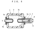
- Fig. 6 shows a conventional gas-filled electric discharge tube 1 as disclosed above, wherein at the opposite open ends of a tubular body 2 formed of an electrically insulating material such as ceramic, there are formed a pair of electrode bases 4a and 4b airtightly adhered to the respective open ends for installing electrodes 3a and 3b as discharge electrodes which are formed by pressing a porous metal sheet on the respective electrode bases 4a and 4b, and to this structure, a gas-filled tube 5 is airtightly mounted on one electrode base 4a, and a connecting portion 6 (which is explained later on) is protrudingly formed on the other electrode base 4b.
- a connecting portion 6 which is explained later on
- a gas-filled discharge tube 1 is formed such that a high-pressurized inert gas is injected into the tubular body 2 from the gas-filled tube 5, and after the completion of the gas injection, the tube 5 is sealed by a gas sealing member 7, and thereafter a cylindrical shaped protection terminal 8 is provided to cover the external side of the tube 5, and further, an electrically conducting adhesive member 9 is filled between the protection terminal 8 and the tube 5.
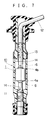
- the gas-filled discharge tube 1 as constructed above is, as shown in Fig. 7, incorporated into a plug gap 10 which is to be engaged with a terminal of the spark plug, whereby a pair of intermediate connecting terminals 14, 14, which are formed respectively at one end of the connecting terminal 11 to be connected to the spark plug and at one end of a cable terminal 13 connected to an end portion of a high-voltage cable 12, are engageably fixed respectively with the protection terminal 8 of the electrode base 4a and the connecting portion 6 of the electrode base 4b of the gas-filled discharge tube 1, so that a so-called series gap is connected in series to the spark plug.
- the present invention has been made to eliminate such problems as described above, and it is an object of the present invention to provide a discharge tube which is capable of making the discharge tube itself smaller to minimize a plug cap that incorporates the discharge tube therein, thereby to realize a minimization of the size of the whole ignition system having a series gap.
- the gas-filled discharge tube is constructed such that it comprises a tubular body formed of an electrically insulating material and having a notch portion at least one of the opposite open ends thereof, and a notch or projecting portion at the other open end thereof; a pair of electrode bases, at least one of which is formed of an electrically conducting thin metal sheet, airtightly adhered to the respective open ends; and a pair of discharge electrodes having flange portions to be engageably fixed with the notch and/or projecting portions and sandwiched between the tubular body and the respective electrode bases, and with this construction, the electrode base is first formed with a gas filling bore by a laser beam for filling an inert gas, which bore being welded also by the laser beam after the inert gas is filled in the tubular body so as to enclose the gas therein.
- the present invention since it is constructed such that at least one of the electrode bases which are supporting discharge electrodes and airtightly adhered to the electrically insulating tubular body is formed of an electrically conducting thin sheet, and this electrode base is formed with a bore which is made by a laser beam for filling an inert gas and welded also by the laser beam after the inert gas filling operation is completed to enclose the filled gas, it is no longer necessary to use a gas-enclosed tube to inject a gas to the tubular body because of the above gas filling bore, so that the above conventionally adopted gas-enclosed tube that largely protrudes from the electrode base can be obviated, thereby a reduction of the whole length of the gas-filled discharge tube can be made possible.
- reference numeral 1 denotes a gas-filled discharge tube
- numeral 2 denotes a tubular body
- 3a and 3b respectively denote electrodes
- 4a and 4b respectively denote electrode bases
- 5 a gas-enclosed tube 6
- 8 a protection terminal
- 10 a plug cap
- 14 an intermediate connecting terminal
- 16 a gas filling bore
- 17 an electrically conducting spring
- 18 a carrier belt
- 19 a welding device
- reference numeral 21 denotes an installing projection.
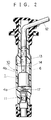
- Fig. 1 is an illustration showing one embodiment of a gas-filled discharge tube 1 according to the present invention, in which the discharge tube comprises a tubular body 2 formed of an electrically insulating material such as ceramic, one end of which is formed with an aperture 2a of a large diameter, while the other end thereof is formed with the other aperture 2b of a small diameter, and further, notch portions 2c, 2c are provided at the respective apertures 2a and 2b.
- the discharge tube comprises a tubular body 2 formed of an electrically insulating material such as ceramic, one end of which is formed with an aperture 2a of a large diameter, while the other end thereof is formed with the other aperture 2b of a small diameter, and further, notch portions 2c, 2c are provided at the respective apertures 2a and 2b.
- discharge electrodes 3a and 3b which are respectively formed by pressing a porous metal sheet so as to fit with each of these apertures, are engageably fixed with these notch portions 2c, 2c of the respective apertures 2a and 2b of the tubular body 2, and these electrodes 3a and 3b are supported by electrode bases 4a and 4b respectively, which are airtightly adhered to the end surfaces of the respective apertures of the tubular body 2 through soldering or the like.
- the electrode base 4a of a large diameter for supporting the electrode 3a of a large diameter is formed of a thin metal sheet whose thickness is below 1.00 mm, and this electrode base 4a is further formed with a dented portion 15 at the center portion thereof to be contacted with an electrically conducting spring 17 (explained later) and the dented portion 15 is further formed with a tiny gas filling bore 16 which is, as explained later on, welded to close after the gas filling operation is completed so as to enclose the gas in the tubular body.
- the other electrode base 4b of a small diameter for supporting the electrode 3b of a small diameter is formed of a lid-like metal sheet, at the center portion of which a connecting portion 6 is protrudingly formed just like the above-explained conventional device.
- a gas-filled discharge tube 1 enclosing an inert gas is, as shown in Fig. 2, incorporated into a plug cap 10 which is to be engageably fixed to a terminal of the spark plug, wherein a spring 17 is suppressedly provided between a connecting terminal 11 to be connected to the spark plug and the electrode base 4a of the discharge tube 1, and a connecting portion 6 of the other electrode base 4b is engageably fixed to an intermediate connecting terminal 14 provided to a cable terminal 13 which is connected to one end of the high-voltage cable 12, thereby forming a so-called series gap connected in series to the spark plug.
- the electrodes 3a and 3b are engageably fixed to the notch portions 2c, 2c of the respective apertures 2a and 2b of the above tubular body 2, and the electrode bases 4a and 4b are airtightly adhered through soldering or the like to the respective end surfaces of the tubular body 2, whereby the discharge tube 1 without inert gas enclosed therein is first assembled.
- the carrier belt 18 is extended to the inner side of a chamber (not shown) having a pressure-proof character, and above the carrier belt 18 within the chamber a welding device 19 such as a YAG laser is movably mounted in respective vertical directions.
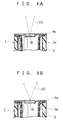
- the carrier belt 18 is moved in a step-by-step form, and when the discharge tube 1 comes just below the welding device 19, the welding device 19 is activated to irradiate a laser beam 20 onto the center portion of the electrode base 4a of the discharge tube 1 for 1 to 10 shots to form a gas filling bore 16 having a diameter 0.3 to 1.00 mm on the electrode base 4a.
- the chamber in which the discharge tube 1 is located is put in a vacuum state, and high-pressurized Argon or Xenon gas and a mixed gas with a rare gas N2 are injected into the chamber so as to fill the chamber with the inert gas.
- the high-pressurized inert gas is filled into the discharge tube 1 by way of the above gas filling bore 16.
- the welding device 19 held at the location where the gas filling bore 16 is formed is slightly moved upward and downward so as to shift the focal point of the laser beam 20 and irradiate the laser beam 20 again onto the center portion of the electrode base 4a of the discharge tube 1.
- the gas filling bore 16 formed on the above discharge tube 1 is welded and sealed, and a gas-filled discharge tube having a high-pressurized inert gas enclosed therein is thereby formed.
- an electrode base 4a of a large diameter airtightly adhered to the tubular body 2 for supporting the electrode 3a of a large diameter is formed of a thin metal sheet, and is also formed with a gas filling bore 16 by a laser beam 20 which bore is welded to be closed also by the laser beam 20 after the inert gas filling operation is completed, the gas can be filled into the tubular body 2 by way of the gas filling bore 16 obviating the use of a conventionally adopted gas-enclosed tube, and the gas-enclosed tube largely protruding from the electrode base 4 can also be unneeded, thereby enabling to shorten the whole length of the gas-filled discharge tube 1.
- the plug cap 10 of an ignition system having a so-called series gap for incorporating this discharge tube 1 therein can also be minimized, so that the whole ignition system having a series gap can be minimized, and due to this fact, an engine room adopting such ignition system can have more space for other functions.
- gas filling bore 16 which has been formed by a laser beam 20 can be easily welded only by shifting the focal point of the laser beam 20, a laser beam treating operation itself can be largely facilitated, and thereby the productivity thereof can be enormously improved.
- both of the electrode bases 4a and 4b airtightly adhered to the opposite end portions of the tubular body 2 can be respectively formed of thin metal sheets, and the electrodes 3a and 3b to be engageably fixed to the tubular body 2 can be formed of a same diameter.
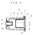
- Fig. 5 is an illustration showing a gas-filled discharge tube according to another embodiment of the present invention.
- the inner peripheral wall 2d of the tubular body 2 is formed as thin as possible to the extent that it can endure the high-pressure of the inert gas filled into the tubular body 2, and in addition, an installing projection 21 is formed at the aperture 2a of a large diameter of the tubular body 2, whereby a flange portion 3a' of a the large diameter electrode 3a is engageably fixed to the aperture 2a.
- an electrode base 4a of a large diameter is further airtightly adhered to the end surface 21a of the installing projection 21.
- the electrode base 4a is formed of a thin metal sheet, and that the gas filling bore 16 formed in the electrode base 4a is welded to seal the bore after the inert gas is filled therein.
- the gas can be filled into the tubular body 2 by way of the gas filling bore 16 without using a conventionally adopted gas-enclosed tube, so that the gas-enclosed tube largely protruding from the electrode base 4 can also be unneeded, thereby the whole length of the gas-filled discharge tube 1 can be shortened. Further, by minimizing the size of the gas-filled discharge tube 1 as above, the whole ignition system having a series gap can be minimized.
- the weight of the whole gas-filled electric discharge tube 1 can be reduced, and by minimizing the quantity of an electrically insulating material such as ceramic forming the tubular body 2, the manufacturing cost for the whole discharge tube 1 can be also reduced, so that the total weight of the whole ignition system having a series gap to incorporate this discharge tube 1 therein, and the total cost for its production can also be greatly reduced.
- a gas-filled discharge tube is constructed such that it comprises a tubular body formed of an electrically insulating material, and electrode bases to be airtightly adhered thereto, at least one of which electrode bases being formed of an electrically conducting thin sheet, wherein the electrode base is formed with a gas filling bore 16 by a laser beam so as to first fill the gas, and then welded to close the bore by the laser beam after the inert gas filling operation is completed, whereby the inert gas can be filled into the tubular body 2 by way of the gas filling bore without using a conventionally adopted gas-enclosed tube, so that the conventional gas-enclosed tube largely protruding from the electrode base 4 can also be unneeded, and thereby the whole length of the gas-filled electric discharge tube 1 can be shortened, and consequently, the size of the whole ignition system having a series gap for incorporating the discharge tube therein can be minimized.
Landscapes
- Spark Plugs (AREA)
- Lasers (AREA)
- Vessels And Coating Films For Discharge Lamps (AREA)
Applications Claiming Priority (6)
| Application Number | Priority Date | Filing Date | Title |
|---|---|---|---|
| JP7200091 | 1991-04-05 | ||
| JP72000/91 | 1991-04-05 | ||
| JP63576/92 | 1992-03-19 | ||
| JP6357692A JPH0574550A (ja) | 1991-04-05 | 1992-03-19 | ガス入り放電管 |
| JP15084/92U | 1992-03-23 | ||
| JP1508492U JPH065177U (ja) | 1992-03-23 | 1992-03-23 | 放電管 |
Publications (3)
| Publication Number | Publication Date |
|---|---|
| EP0507330A2 true EP0507330A2 (de) | 1992-10-07 |
| EP0507330A3 EP0507330A3 (en) | 1992-11-19 |
| EP0507330B1 EP0507330B1 (de) | 1996-01-24 |
Family
ID=27280870
Family Applications (1)
| Application Number | Title | Priority Date | Filing Date |
|---|---|---|---|
| EP19920105798 Expired - Lifetime EP0507330B1 (de) | 1991-04-05 | 1992-04-03 | Gasgefüllte Entladungsröhre |
Country Status (3)
| Country | Link |
|---|---|
| EP (1) | EP0507330B1 (de) |
| CA (1) | CA2064942C (de) |
| DE (1) | DE69207798T2 (de) |
Cited By (1)
| Publication number | Priority date | Publication date | Assignee | Title |
|---|---|---|---|---|
| GB2561978A (en) * | 2017-03-22 | 2018-10-31 | Champion Aerospace Llc | Spark gap assembly with non-radioactive gas fill |
Family Cites Families (3)
| Publication number | Priority date | Publication date | Assignee | Title |
|---|---|---|---|---|
| EP0229303A1 (de) * | 1985-12-18 | 1987-07-22 | Cerberus Ag | Funkenstrecke, insbesondere zur Verwendung als Vorfunkenstrecke einer Zündkerze eines Verbrennungsmotors |
| US5166574A (en) * | 1989-07-14 | 1992-11-24 | Yazaki Corporation | High-tension cable device |
| JPH0353481A (ja) * | 1989-07-19 | 1991-03-07 | Yazaki Corp | 放電管 |
-
1992
- 1992-04-02 CA CA 2064942 patent/CA2064942C/en not_active Expired - Fee Related
- 1992-04-03 EP EP19920105798 patent/EP0507330B1/de not_active Expired - Lifetime
- 1992-04-03 DE DE1992607798 patent/DE69207798T2/de not_active Expired - Fee Related
Cited By (1)
| Publication number | Priority date | Publication date | Assignee | Title |
|---|---|---|---|---|
| GB2561978A (en) * | 2017-03-22 | 2018-10-31 | Champion Aerospace Llc | Spark gap assembly with non-radioactive gas fill |
Also Published As
| Publication number | Publication date |
|---|---|
| DE69207798T2 (de) | 1996-05-30 |
| EP0507330B1 (de) | 1996-01-24 |
| DE69207798D1 (de) | 1996-03-07 |
| EP0507330A3 (en) | 1992-11-19 |
| CA2064942C (en) | 1998-11-03 |
| CA2064942A1 (en) | 1992-10-06 |
Similar Documents
| Publication | Publication Date | Title |
|---|---|---|
| JP4977921B2 (ja) | テーパ付き内部焼成抑制器シールを有するスパークプラグ | |
| KR19990044549A (ko) | 고압 방전 램프 | |
| CA2300236C (en) | Broad range surge absorber without chips | |
| US5352953A (en) | Gas-filled discharge tube | |
| JPH05283140A (ja) | サージアブソーバ | |
| EP0507330B1 (de) | Gasgefüllte Entladungsröhre | |
| JPH11204131A (ja) | 密閉型電池 | |
| MXPA03006513A (es) | Bujia. | |
| US4853596A (en) | Flash discharge lamp with sintered cathode member | |
| JPH0622946Y2 (ja) | ガス入り放電管 | |
| US5053676A (en) | High-pressure discharge lamp | |
| EP0069311B1 (de) | In einem Glasgehäuse gekapselter Quarzresonator | |
| JPH0668949A (ja) | 避雷器 | |
| JP4737350B2 (ja) | 圧力容器の気体封入方法 | |
| CA2020587C (en) | Gas-filled discharge tube and high-tension cable device | |
| KR100712745B1 (ko) | 전기 램프 | |
| JPH0574550A (ja) | ガス入り放電管 | |
| EP0407987B1 (de) | Verfahren zur Herstellung einer gasverschmolzenen Entladungsröhre | |
| US5772487A (en) | Method for manufacturing metal halide lamp | |
| JPH0641050U (ja) | 密閉式角形電池 | |
| JPH07176321A (ja) | 角形密閉電池の製造方法 | |
| JP2001135454A (ja) | サージアブソーバ及びその製造方法 | |
| JPH03105071A (ja) | シリーズギャップ付き点火コイル | |
| JP3507618B2 (ja) | 絶縁性容器の開口封鎖用の金属封塞体の両面に金属体を取りつける方法および間隙素子 | |
| JP2542984Y2 (ja) | 高電圧抵抗パック |
Legal Events
| Date | Code | Title | Description |
|---|---|---|---|
| PUAI | Public reference made under article 153(3) epc to a published international application that has entered the european phase |
Free format text: ORIGINAL CODE: 0009012 |
|
| PUAL | Search report despatched |
Free format text: ORIGINAL CODE: 0009013 |
|
| AK | Designated contracting states |
Kind code of ref document: A2 Designated state(s): DE FR GB IT |
|
| AK | Designated contracting states |
Kind code of ref document: A3 Designated state(s): DE FR GB IT |
|
| 17P | Request for examination filed |
Effective date: 19930203 |
|
| 17Q | First examination report despatched |
Effective date: 19940510 |
|
| GRAA | (expected) grant |
Free format text: ORIGINAL CODE: 0009210 |
|
| AK | Designated contracting states |
Kind code of ref document: B1 Designated state(s): DE FR GB IT |
|
| REF | Corresponds to: |
Ref document number: 69207798 Country of ref document: DE Date of ref document: 19960307 |
|
| ITF | It: translation for a ep patent filed | ||
| ET | Fr: translation filed | ||
| PLBE | No opposition filed within time limit |
Free format text: ORIGINAL CODE: 0009261 |
|
| STAA | Information on the status of an ep patent application or granted ep patent |
Free format text: STATUS: NO OPPOSITION FILED WITHIN TIME LIMIT |
|
| 26N | No opposition filed | ||
| REG | Reference to a national code |
Ref country code: GB Ref legal event code: IF02 |
|
| PGFP | Annual fee paid to national office [announced via postgrant information from national office to epo] |
Ref country code: GB Payment date: 20070328 Year of fee payment: 16 |
|
| PGFP | Annual fee paid to national office [announced via postgrant information from national office to epo] |
Ref country code: DE Payment date: 20070329 Year of fee payment: 16 |
|
| PGFP | Annual fee paid to national office [announced via postgrant information from national office to epo] |
Ref country code: IT Payment date: 20070622 Year of fee payment: 16 |
|
| PGFP | Annual fee paid to national office [announced via postgrant information from national office to epo] |
Ref country code: FR Payment date: 20070411 Year of fee payment: 16 |
|
| GBPC | Gb: european patent ceased through non-payment of renewal fee |
Effective date: 20080403 |
|
| PG25 | Lapsed in a contracting state [announced via postgrant information from national office to epo] |
Ref country code: DE Free format text: LAPSE BECAUSE OF NON-PAYMENT OF DUE FEES Effective date: 20081101 |
|
| REG | Reference to a national code |
Ref country code: FR Ref legal event code: ST Effective date: 20081231 |
|
| PG25 | Lapsed in a contracting state [announced via postgrant information from national office to epo] |
Ref country code: FR Free format text: LAPSE BECAUSE OF NON-PAYMENT OF DUE FEES Effective date: 20080430 |
|
| PG25 | Lapsed in a contracting state [announced via postgrant information from national office to epo] |
Ref country code: GB Free format text: LAPSE BECAUSE OF NON-PAYMENT OF DUE FEES Effective date: 20080403 |
|
| PG25 | Lapsed in a contracting state [announced via postgrant information from national office to epo] |
Ref country code: IT Free format text: LAPSE BECAUSE OF NON-PAYMENT OF DUE FEES Effective date: 20080403 |