EP0506444B1 - Electronic balance - Google Patents
Electronic balance Download PDFInfo
- Publication number
- EP0506444B1 EP0506444B1 EP92302690A EP92302690A EP0506444B1 EP 0506444 B1 EP0506444 B1 EP 0506444B1 EP 92302690 A EP92302690 A EP 92302690A EP 92302690 A EP92302690 A EP 92302690A EP 0506444 B1 EP0506444 B1 EP 0506444B1
- Authority
- EP
- European Patent Office
- Prior art keywords
- pulse
- pulses
- electronic balance
- processing
- balance
- Prior art date
- Legal status (The legal status is an assumption and is not a legal conclusion. Google has not performed a legal analysis and makes no representation as to the accuracy of the status listed.)
- Expired - Lifetime
Links
- 238000006073 displacement reaction Methods 0.000 claims description 26
- 238000012545 processing Methods 0.000 claims description 23
- 230000010354 integration Effects 0.000 claims description 6
- 238000006243 chemical reaction Methods 0.000 claims description 3
- 238000001514 detection method Methods 0.000 claims description 3
- 230000007246 mechanism Effects 0.000 description 14
- 230000008859 change Effects 0.000 description 9
- 238000000034 method Methods 0.000 description 9
- 238000010586 diagram Methods 0.000 description 8
- 230000010355 oscillation Effects 0.000 description 4
- 238000001914 filtration Methods 0.000 description 3
- 230000003287 optical effect Effects 0.000 description 3
- 238000012935 Averaging Methods 0.000 description 2
- 239000003990 capacitor Substances 0.000 description 2
- 230000004069 differentiation Effects 0.000 description 2
- 238000005259 measurement Methods 0.000 description 2
- 230000004044 response Effects 0.000 description 2
- 238000007796 conventional method Methods 0.000 description 1
- 230000003247 decreasing effect Effects 0.000 description 1
- 230000000694 effects Effects 0.000 description 1
- 230000009467 reduction Effects 0.000 description 1
- 230000001105 regulatory effect Effects 0.000 description 1
- 229910000859 α-Fe Inorganic materials 0.000 description 1
Images

Classifications
-
- G—PHYSICS
- G01—MEASURING; TESTING
- G01G—WEIGHING
- G01G7/00—Weighing apparatus wherein the balancing is effected by magnetic, electromagnetic, or electrostatic action, or by means not provided for in the preceding groups
- G01G7/02—Weighing apparatus wherein the balancing is effected by magnetic, electromagnetic, or electrostatic action, or by means not provided for in the preceding groups by electromagnetic action
- G01G7/04—Weighing apparatus wherein the balancing is effected by magnetic, electromagnetic, or electrostatic action, or by means not provided for in the preceding groups by electromagnetic action with means for regulating the current to solenoids
- G01G7/045—Weighing apparatus wherein the balancing is effected by magnetic, electromagnetic, or electrostatic action, or by means not provided for in the preceding groups by electromagnetic action with means for regulating the current to solenoids having a PID control system
Definitions
- the present invention relates to an electronic balance and more particularly to an electronic balance of the electromagnetic force balancing type.
- an electromagnetic force generated at the time when a current flows in a force coil disposed in a magnetic field is used as a counterbalance force with respect to the weight of a load to be measured, and the weight of such a load is obtained based on the value of a current required for obtaining an equilibrium between the load weight and the electromagnetic force.
- the electronic balance of the type above-mentioned may be divided into the following types according to the method of supplying the current to the force coil, the method of measuring the current value and the like:
- the method (1) is disadvantageous in view of limited resolution and response characteristics. More specifically, the cycle of a pulse current flowing in the force coil is limited to about max. 2 milliseconds due to the number of vibrations inherent in the balance mechanism. If the cycle exceeds 2 milliseconds, the balance beam is considerably vibrated. Accordingly, it is required to measure the pulse width changing in this cycle of 2 milliseconds by counting clock pulses. However, even though clock pulses of 30 MHz are used and counted, there is merely obtained max. 60,000 counts (about 16 bits on the binary scale) which is the limit of resolution to be obtained where general-purpose ICs are used.
- the resolution can be improved.
- the method (2) presents the following problems. That is, in measurement of the weight of a load which undergoes a change from time to time, or in measurement of weighing-out or the like, the pulse duty determined in N steps is changed by one step at the moment when the weight exceeds the range to be measured by the servo system. At this time, there is temporarily produced an excessive force compensation due to the response characteristics of a PID control output of the servo system. This causes the balance mechanism to be swung so that the measured and displayed value is temporarily considerably changed.
- the method (3) above-mentioned requires an A/D conversion function with high precision. This requires high stability for both the servo system and the A/D converter. Thus, both the resolution and the stability are hardly assured.
- the analog servo mechanism a certain limit is placed upon integration of the circuit thereof and a number of portions in the circuit should be adjusted. It is therefore difficult to uniformalize the respective performances of electronic balances each using such an analog servo mechanism.
- the inventor has already proposed an electronic balance in which (i) pulse currents flow in force coils, (ii) there is fetched, as a digital signal, a signal which represents a displacement of the load receiving member and which is detected for detecting the balancing state of the balance, (iii) this digital signal is subjected to digital PID operations (proportion, integration and differentiation processings), and (iv) the duties of pulse currents to flow in the force coils are determined based on the operation results (Japanese Patent Laid-Open Publication 3-63526).
- the resolution (the number of bits) of each pulse current generating means is limited to a certain level, the total sum of respective resolutions is regarded as the resolution of the balance in its entirety.
- the resolution of the balance in its entirety can be advantageously improved as desired by increasing the number of pulse current generating means and the number of divisions of pulse duty data.
- the present invention provides an electronic balance a pulse current having any of duties determined based on resolution coarser than the display resolution of the balance, is supplied to the force coil.
- the duty of the pulse current undergoes a change at a predetermined rate in a predetermined period of time.
- the pulse current duty is determined in the following manner.
- An output of a displacement sensor for detecting the balancing state of the balance is subjected to automatic control processings such as PID operations and, then converted into pulse duty data in a data processing unit.
- the pulse duty data is then supplied to pulse current generating means to change the duty of a pulse current supplied therefrom.
- the display value of the balance is obtained by converting the duty of the pulse current flowing in the force coil, into a mass value.
- the resolution can be substantially improved by two digits. More specifically, when a pulse current having one type of peak value is simply supplied to one force coil and the clock pulse for measuring the pulse width is set to 30 MHz for example, the resolution is limited to about one ten-thousandsth. On the other hand, the balance according to the present invention is improved in resolution to about one millionsth.
- the electronic balance of the present invention is advantageous in view of cost as compared with the balance according to the proposal mentioned earlier.
- the electronic balance of the present invention is considerably improved in stability of a display value with respect to disturbance as compared with any of the conventional balances.
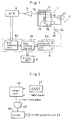
- Fig. 1 is a block diagram illustrating the arrangement of a preferred embodiment of the present invention.
- a balance mechanism 1 is a load-weight detecting mechanism of the electromagnetic force balancing type known per se.
- a force coil 13 is disposed in a magnetic field formed by a magnetic circuit (not shown).
- a current flows in this force coil 13
- an electromagnetic force is generated.
- the electromagnetic force thus generated acts on a load receiving member 12 connected to a plate 11 and is so controlled as to be brought in equilibrium with a load weight W on the plate 11 as set forth below.
- a movable unit including the plate 11 is preferably regulated in movement in a vertical direction only by a Roberval's mechanism (not shown) (also called a parallel guide).
- the equilibrium above-mentioned can be obtained in the following manner.
- An output of a displacement sensor 14 for detecting a displacement of the load receiving member 12 in the balance mechanism 1 is converted into digital data, which is then processed by a microcomputer 5, to be discussed later, thereby to change the current flowing in the force coil 13.
- a signal representing a displacement of the load receiving member 12 as detected by the displacement sensor 14 is amplified by a preamplifier 3, digitalized by an A/D converter 4 and sent to the microcomputer 5.
- the microcomputer 5 is shown in the form of a block diagram as divided by function for the convenience of description.
- the functions achieved by the microcomputer 5 according to programs stored in a ROM of the microcomputer 5.
- the microcomputer 5 comprises conventional hardware such as CPU, ROM, RAM and the like.
- a practical circuit serving as the A/D converter 4 may comprise a saw-tooth wave generator 41 for supplying saw-tooth waves at predetermined cycles, a comparator 42 for receiving an output of the saw-tooth wave generator 41 and an output of the displacement sensor 14, an AND gate 43 for receiving an output of the comparator 42 and a clock pulse, and a counter 44 for counting the clock pulse passing through the AND gate 43.
- An output of the comparator 42 forms a pulse-width signal correlative to the magnitude of an input signal. By counting clock pulses with the pulse-width signal serving as a gate signal, digitalized data of a displacement detection signal is obtained every cycle of saw-tooth waves.
- the digitalized displacement data is fetched by a PID operation unit 51 where the data is subjected to digital PID processings, i.e., proportion, integration and differentiation processings.
- Outputs of the PID operation unit 51 are sent, through a data processing unit 52, to a pulse duty converting unit 53, where a pulse duty signal is formed and sent to a pulse current generator 2. Provision is made such that an output of the data processing unit 52 is displayed, as a calculated value, on a display unit 6.
- the pulse current generator 2 comprises a constant current generating circuit 21 and an electronic switch 22 adapted to be opened/closed according to a duty signal from the pulse duty converting unit 53.
- the pulse current generator 2 is to generate a pulse current which has a constant peak value based on an output current from the constant current generating circuit 21 and of which duty is corresponding to data from the pulse duty converting unit 53.
- the pulse current thus generated is supplied to the force coil 13.
- the pulse duty converting unit 53 basically supplies a duty signal of which ratio of H (high) and L (low) varies at predetermined cycles according to digital data from the data processing unit 52.
- the electronic switch 22 is turned ON/OFF.
- the electronic switch 22 is adapted to chop a direct current from the constant current generating circuit 21.
- a pulse current of which duty varies with output data from the data processing unit 52 flows in the force coil 13.
- This embodiment is characterized in that, when it is supposed that the required resolution of the balance is set to 1/1,000,000 for example, a duty signal generated by the pulse duty converting unit 53 normally requires 20 bits but the duty signal in this embodiment has 16 bits. More specifically, when it is supposed that the frequency of a clock pulse in the pulse duty converter unit is equal to 30 MHz and the cycle of the pulse duty is equal to 2 milli-seconds, the inside value counted by the counter 44 is limited to 60,000 counts which is roughly equal to 16 bits. The shortage of the number of bits is compensated by periodically increasing or decreasing the duty signal as discussed later. Accordingly, a pulse current substantially having high resolution flows in the force coil 13.
- temperature compensation is given for a current generated by the constant current generating circuit 21 such that the current,varies at a rate equal to that of variation of the magnetic field strength in the magnetic circuit.
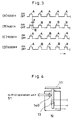
- the pulse duty converting unit 53 merely generates a duty signal having 16-bit resolution. Accordingly, when this signal is processed, the subsequent data to data 5000H for example is 5001H. On the other hand, the balance is required to have resolution of 20 bits for example.
- the duty of a pulse duty signal for forming data 5001H is increased by a width t corresponding to the 16-bit resolution, as compared with that for 5000H.
- the pulses in 5000H and the pulses in 5001H in Fig. 3 are respectively designated by A and B.
- the pulse duty converting unit 53 when forming a hexadecimal digit of 50001H using a signal having such resolution, the pulse duty converting unit 53 generates fifteen pulses A of 5000H and one pulse B of 5001H during one cycle of sixteen pulse generations, as shown in Fig. 3 (C). For generating 50002H, the pulse duty converting unit 53 generates fourteen pulses A and two pulses B during one cycle of sixteen pulse generations. For generating 50008H, the pulse duty converting unit 53 generates eight pulses A and eight pulses B during one cycle of sixteen pulse generations as shown in Fig. 3 (D).
- the pulse B having a large width is generated a plurality of times during one cycle of sixteen pulse generations, it is advantageous in view of filtering to disperse the pulses B at regular time intervals during one cycle as shown in Fig. 3. More specifically, when the movable unit including the load receiving member 12 is vibrated due to a pulse current flowing in the force coil 13, it is more advantageous that the pulse current flows as averaged in the manner above-mentioned. Further, generating the pulses at regular time intervals above-mentioned is advantageous in view of less occurrence of ripples at the time of filtering even though there is adopted a system in which the pulse current is passed through a filter circuit, causing the pulse current to be converted into a direct current, which flows in the force coil 13.
- the pulse current above-mentioned which is generated as chopped based on the pulse duty signal and which has an effective current value equivalently equal to the weight of a load. Accordingly, when the balance mechanism 1 is brought in equilibrium, an output of the A/D converter 4 is equal to 0 or a predetermined reference value. (For example, one half of the counted value on full scale would be preferable when the A/D converter which does not measure a minus value is used.) Thus, the number of bits, lineality, span variations and the like of the A/D converter 4 can be disregarded. That is, the A/D converter 4 is required to work until the balance mechanism 1 is brought in equilibrium. Accordingly, only zero stability is important in the A/D converter 4.
- the sensor is not limited to one of the analog type.
- a CCD line sensor 140 of the digital type as shown in Fig. 4 may be used as the displacement sensor. In this case, the A/D converter 4 becomes unnecessary.
- any of the following sensors may also be used in addition to the sensor of the type using an optical signal; a sensor in which a capacitor of the parallel plate type secured to the load receiving member 12 and to the stationary portion of the balance mechanism, is adapted to be changed in capacity by a displacement of the load receiving member 12, so that an oscillation circuit including the capacitor is changed in oscillation frequency, which is used as an output of the sensor; and a sensor in which a coil and a ferrite core are respectively secured to the stationary portion of the balance mechanism and the load receiving member, and the coil is adapted to be changed in inductance by a displacement of the load receiving member, so that an oscillation circuit including the coil is changed in oscillation frequency, which is used as an output of the sensor.
- Fig. 5 is a block diagram illustrating the arrangement of the main circuit of electronic balance according to a further embodiment of the present invention.
- an output of a displacement sensor 14 of the analog type is amplified by an amplifier 501 and then processed by an analog PID operation circuit 502, and an output of the PID operation circuit 502 is digitalized by an A/D converter 503 and then sent to a microcomputer 504. Then, the microcomputer 504 generates a pulse duty signal, as mentioned earlier, based on the digital data.
- the microcomputer 504 generates a pulse duty signal, as mentioned earlier, based on the digital data.
- Fig. 6 shows a block diagram illustrating the arrangement of the main circuit of electronic balance according to still another embodiment of the present invention.
- an output of a displacement sensor 14 of the analog type is amplified by an amplifier 601 and then processed by an analog PD operation circuit 602.
- An output of the PD operation circuit 602 is digitalized by an A/D converter 603 and then sent to a microcomputer 604.
- the digital data is integrated by a digital operation to form a PID signal.
- the PID signal is then converted into a pulse duty signal as mentioned earlier in the same manner as mentioned earlier.
- the arrangement shown in Fig. 6 may be modified such that an output of the amplifier 601 is sent to an analog PD operation circuit 602 and at the same time, the output of the amplifier 601 is digitalized and sent to the microcomputer 604.
- the digitalized data is subjected to an integration processing.
- the integration result data is composed with data as obtained by digitalizing the result of the analog PD operation.
- the equipment described uses conventional 16-bit digital circuitry to generate gating pulses with a 2 milli-second period from a 30 MHz clock with the width of the gating pulses controlled by the position sensor which determines when the electromagnetic force is balancing the load.
- Each gating pulse period is determined by 60,000 clock pulses and since the smallest possible change in the gating pulse width is one clock pulse the resolution is of the order of 1 in 10,000. This is governed by the fact that only 16 bits are available from the standard digital circuit elements which are used.
- successive groups of gating pulses are caused to include increasing numbers of pulses which have a width changed by one unit (clock pulse).
- clock pulse a unit
- gating pulse width is changed in steps of one unit (one clock pulse), giving a coarse adjustment, and close to equilibrium the proportions of narrower and wider pulses in a group are changed progressively to give the fine adjustment.
Applications Claiming Priority (2)
| Application Number | Priority Date | Filing Date | Title |
|---|---|---|---|
| JP63137/91 | 1991-03-27 | ||
| JP6313791 | 1991-03-27 |
Publications (3)
| Publication Number | Publication Date |
|---|---|
| EP0506444A2 EP0506444A2 (en) | 1992-09-30 |
| EP0506444A3 EP0506444A3 (en) | 1993-04-21 |
| EP0506444B1 true EP0506444B1 (en) | 1996-03-06 |
Family
ID=13220585
Family Applications (1)
| Application Number | Title | Priority Date | Filing Date |
|---|---|---|---|
| EP92302690A Expired - Lifetime EP0506444B1 (en) | 1991-03-27 | 1992-03-27 | Electronic balance |
Country Status (4)
| Country | Link |
|---|---|
| US (1) | US5270497A (un) |
| EP (1) | EP0506444B1 (un) |
| CN (1) | CN1065332A (un) |
| DE (1) | DE69208702T2 (un) |
Families Citing this family (4)
| Publication number | Priority date | Publication date | Assignee | Title |
|---|---|---|---|---|
| JP2005201850A (ja) * | 2004-01-19 | 2005-07-28 | Shimadzu Corp | 電子天びん |
| EP1925919A1 (de) * | 2006-11-24 | 2008-05-28 | Mettler-Toledo AG | Wägezelle |
| US8926171B2 (en) * | 2009-04-29 | 2015-01-06 | Waters Technologies Corporation | Simultaneous differential thermal analysis system |
| EP2910914B1 (de) * | 2014-02-21 | 2018-01-31 | Multipond Wägetechnik GmbH | Wägevorrichtung und Verfahren zum Betreiben der Wägevorrichtung |
Family Cites Families (11)
| Publication number | Priority date | Publication date | Assignee | Title |
|---|---|---|---|---|
| DE2722093C2 (de) * | 1977-05-16 | 1979-02-15 | Hartmut Dipl.-Phys. Dr. 6203 Hochheim Gruetzediek | Gewichts- und Kraftmeßeinrichtung |
| CH619779A5 (un) * | 1977-09-20 | 1980-10-15 | Mettler Instrumente Ag | |
| CH634654A5 (de) * | 1978-10-20 | 1983-02-15 | Mettler Instrumente Ag | Waage mit elektromagnetischer lastkompensation. |
| US4365680A (en) * | 1979-06-25 | 1982-12-28 | Dietrich Gottstein | Force measuring device |
| US4372406A (en) * | 1980-04-30 | 1983-02-08 | Shimadzu Corporation | Electronic balance |
| JPS5833129A (ja) * | 1981-08-21 | 1983-02-26 | Shimadzu Corp | 電子天びん |
| CH655182A5 (de) * | 1982-02-10 | 1986-03-27 | Mettler Instrumente Ag | Elektromagnetisch kompensierende waage. |
| CH660525B (un) * | 1983-09-29 | 1987-04-30 | ||
| US4685114A (en) * | 1986-02-27 | 1987-08-04 | The Charles Stark Draper Laboratory, Inc. | Waveform modulation system |
| CH675158A5 (un) * | 1988-06-14 | 1990-08-31 | Mettler Toledo Ag | |
| JPH0363526A (ja) * | 1989-07-31 | 1991-03-19 | Shimadzu Corp | 電子天びん |
-
1992
- 1992-03-20 US US07/854,934 patent/US5270497A/en not_active Expired - Fee Related
- 1992-03-23 CN CN92102012.0A patent/CN1065332A/zh active Pending
- 1992-03-27 EP EP92302690A patent/EP0506444B1/en not_active Expired - Lifetime
- 1992-03-27 DE DE69208702T patent/DE69208702T2/de not_active Expired - Fee Related
Also Published As
| Publication number | Publication date |
|---|---|
| US5270497A (en) | 1993-12-14 |
| EP0506444A3 (en) | 1993-04-21 |
| CN1065332A (zh) | 1992-10-14 |
| DE69208702T2 (de) | 1996-08-29 |
| DE69208702D1 (de) | 1996-04-11 |
| EP0506444A2 (en) | 1992-09-30 |
Similar Documents
| Publication | Publication Date | Title |
|---|---|---|
| US4420055A (en) | Apparatus for measuring weight and force | |
| EP0144834B1 (en) | Load cell type weight-measuring device | |
| EP0506444B1 (en) | Electronic balance | |
| US4549623A (en) | Apparatus for automatically monitoring a constant current source in a measuring instrument | |
| EP0617265B1 (en) | A force measuring instrument | |
| CN1029028C (zh) | 电子秤 | |
| JP3077357B2 (ja) | 電子天びん | |
| JP3104380B2 (ja) | 電子天びん | |
| US4365680A (en) | Force measuring device | |
| JP2687624B2 (ja) | 電子天びん | |
| JP2569486B2 (ja) | 電子天びん | |
| KR960012744B1 (ko) | 전자저울 | |
| JP2687625B2 (ja) | 電子天びん | |
| EP0073154B2 (en) | Electronic balance | |
| JPS6275214A (ja) | 電子天びん | |
| JP2604040B2 (ja) | 自動平衡式測定器 | |
| JPH04329320A (ja) | 電子天びん | |
| JP3473196B2 (ja) | 電子天びん | |
| JP3077358B2 (ja) | 電子天びん | |
| SU1631305A1 (ru) | Цифровые электромагнитные весы | |
| SU909583A1 (ru) | Весы с электромагнитным уравновешиванием | |
| JPH02196523A (ja) | Δς変調形a/d変換器の試験回路 | |
| JPS61201119A (ja) | 電子天びん | |
| JPS63241428A (ja) | 電子天びん | |
| JPS5833127A (ja) | 電子天びん |
Legal Events
| Date | Code | Title | Description |
|---|---|---|---|
| PUAI | Public reference made under article 153(3) epc to a published international application that has entered the european phase |
Free format text: ORIGINAL CODE: 0009012 |
|
| AK | Designated contracting states |
Kind code of ref document: A2 Designated state(s): CH DE FR LI |
|
| PUAL | Search report despatched |
Free format text: ORIGINAL CODE: 0009013 |
|
| AK | Designated contracting states |
Kind code of ref document: A3 Designated state(s): CH DE FR LI |
|
| 17P | Request for examination filed |
Effective date: 19931001 |
|
| 17Q | First examination report despatched |
Effective date: 19950112 |
|
| GRAH | Despatch of communication of intention to grant a patent |
Free format text: ORIGINAL CODE: EPIDOS IGRA |
|
| GRAA | (expected) grant |
Free format text: ORIGINAL CODE: 0009210 |
|
| AK | Designated contracting states |
Kind code of ref document: B1 Designated state(s): CH DE FR LI |
|
| REG | Reference to a national code |
Ref country code: CH Ref legal event code: NV Representative=s name: ARDIN & CIE S.A. |
|
| REF | Corresponds to: |
Ref document number: 69208702 Country of ref document: DE Date of ref document: 19960411 |
|
| ET | Fr: translation filed | ||
| PLBE | No opposition filed within time limit |
Free format text: ORIGINAL CODE: 0009261 |
|
| STAA | Information on the status of an ep patent application or granted ep patent |
Free format text: STATUS: NO OPPOSITION FILED WITHIN TIME LIMIT |
|
| 26N | No opposition filed | ||
| PGFP | Annual fee paid to national office [announced via postgrant information from national office to epo] |
Ref country code: FR Payment date: 19970313 Year of fee payment: 6 |
|
| PG25 | Lapsed in a contracting state [announced via postgrant information from national office to epo] |
Ref country code: FR Free format text: THE PATENT HAS BEEN ANNULLED BY A DECISION OF A NATIONAL AUTHORITY Effective date: 19980331 |
|
| REG | Reference to a national code |
Ref country code: FR Ref legal event code: ST |
|
| PGFP | Annual fee paid to national office [announced via postgrant information from national office to epo] |
Ref country code: CH Payment date: 20010327 Year of fee payment: 10 |
|
| PG25 | Lapsed in a contracting state [announced via postgrant information from national office to epo] |
Ref country code: LI Free format text: LAPSE BECAUSE OF NON-PAYMENT OF DUE FEES Effective date: 20020331 Ref country code: CH Free format text: LAPSE BECAUSE OF NON-PAYMENT OF DUE FEES Effective date: 20020331 |
|
| REG | Reference to a national code |
Ref country code: CH Ref legal event code: PL |
|
| PGFP | Annual fee paid to national office [announced via postgrant information from national office to epo] |
Ref country code: DE Payment date: 20050324 Year of fee payment: 14 |
|
| PG25 | Lapsed in a contracting state [announced via postgrant information from national office to epo] |
Ref country code: DE Free format text: LAPSE BECAUSE OF NON-PAYMENT OF DUE FEES Effective date: 20061003 |