EP2910914B1 - Wägevorrichtung und Verfahren zum Betreiben der Wägevorrichtung - Google Patents
Wägevorrichtung und Verfahren zum Betreiben der Wägevorrichtung Download PDFInfo
- Publication number
- EP2910914B1 EP2910914B1 EP14156187.8A EP14156187A EP2910914B1 EP 2910914 B1 EP2910914 B1 EP 2910914B1 EP 14156187 A EP14156187 A EP 14156187A EP 2910914 B1 EP2910914 B1 EP 2910914B1
- Authority
- EP
- European Patent Office
- Prior art keywords
- electromagnet
- weighing
- pulse
- control device
- cell
- Prior art date
- Legal status (The legal status is an assumption and is not a legal conclusion. Google has not performed a legal analysis and makes no representation as to the accuracy of the status listed.)
- Not-in-force
Links
- 238000005303 weighing Methods 0.000 title claims description 58
- 238000000034 method Methods 0.000 title claims description 19
- 230000001419 dependent effect Effects 0.000 claims description 5
- 230000004913 activation Effects 0.000 claims description 2
- 230000003044 adaptive effect Effects 0.000 claims description 2
- 238000005259 measurement Methods 0.000 description 24
- 238000010586 diagram Methods 0.000 description 9
- 230000010355 oscillation Effects 0.000 description 8
- 230000001133 acceleration Effects 0.000 description 5
- 230000003068 static effect Effects 0.000 description 5
- 230000000694 effects Effects 0.000 description 4
- 230000005484 gravity Effects 0.000 description 4
- 230000000737 periodic effect Effects 0.000 description 4
- 230000001052 transient effect Effects 0.000 description 4
- 238000013016 damping Methods 0.000 description 3
- 230000003111 delayed effect Effects 0.000 description 2
- 238000006073 displacement reaction Methods 0.000 description 2
- 230000003993 interaction Effects 0.000 description 2
- 230000006978 adaptation Effects 0.000 description 1
- 230000002238 attenuated effect Effects 0.000 description 1
- 239000013590 bulk material Substances 0.000 description 1
- 238000001514 detection method Methods 0.000 description 1
- 238000011161 development Methods 0.000 description 1
- 230000018109 developmental process Effects 0.000 description 1
- 230000005489 elastic deformation Effects 0.000 description 1
- 229920001971 elastomer Polymers 0.000 description 1
- 239000000806 elastomer Substances 0.000 description 1
- 230000001939 inductive effect Effects 0.000 description 1
- 230000003287 optical effect Effects 0.000 description 1
- 230000010363 phase shift Effects 0.000 description 1
Images


Classifications
-
- G—PHYSICS
- G01—MEASURING; TESTING
- G01G—WEIGHING
- G01G23/00—Auxiliary devices for weighing apparatus
- G01G23/02—Relieving mechanisms; Arrestment mechanisms
-
- G—PHYSICS
- G01—MEASURING; TESTING
- G01G—WEIGHING
- G01G7/00—Weighing apparatus wherein the balancing is effected by magnetic, electromagnetic, or electrostatic action, or by means not provided for in the preceding groups
- G01G7/02—Weighing apparatus wherein the balancing is effected by magnetic, electromagnetic, or electrostatic action, or by means not provided for in the preceding groups by electromagnetic action
-
- G—PHYSICS
- G01—MEASURING; TESTING
- G01G—WEIGHING
- G01G23/00—Auxiliary devices for weighing apparatus
- G01G23/06—Means for damping oscillations, e.g. of weigh beams
- G01G23/10—Means for damping oscillations, e.g. of weigh beams by electric or magnetic means
-
- G—PHYSICS
- G01—MEASURING; TESTING
- G01G—WEIGHING
- G01G7/00—Weighing apparatus wherein the balancing is effected by magnetic, electromagnetic, or electrostatic action, or by means not provided for in the preceding groups
- G01G7/02—Weighing apparatus wherein the balancing is effected by magnetic, electromagnetic, or electrostatic action, or by means not provided for in the preceding groups by electromagnetic action
- G01G7/04—Weighing apparatus wherein the balancing is effected by magnetic, electromagnetic, or electrostatic action, or by means not provided for in the preceding groups by electromagnetic action with means for regulating the current to solenoids
Definitions
- the invention relates to a weighing device and a method for operating the weighing device, in particular a weighing device and a method for weighing objects falling on the weighing device.
- This impact impulse transfers impact energy to the load cell.
- This impact energy can deflect the load cell many times over as compared to deflection by the static weight of the objects. This can damage the load cell or reduce its accuracy.
- the impact energy transferred to the load cell has to be reduced.
- the load cell is vibrated according to its natural frequency and the impact energy is converted into heat, for example by internal friction.
- the oscillations do not permit a constant load cell measurement signal indicative of the weight of the objects on the load cell or in the container, the actual weight of the object will be significantly longer than for an object placed on the load cell or in the load cell Container is placed.
- a rigidity of a load cell is increased, so that the load cell can serve as a stop.
- an electromagnet is like that controllable that the rigidity of the load cell can be controlled by a control device so that vibrations of the load cell can be damped quickly and effectively.
- Fig. 1 shows an assembly consisting of a load cell 1 and an electromagnet 2, which is installed in a combination weigher.
- the load cell 1 and the electromagnet 2 are fastened separately to a symbolically shown housing of a weighing device.
- the assembly has an armature 3, which is integrated into the weighing cell 1.
- the armature 3 is not integrated into the load cell 1, but connected in a different way, about it placed on it.
- the electromagnet 2 is optionally provided with a pot coil or a plunger coil.
- the load cell 1 When the weighing cell 1 is loaded by an object to be weighed, the load cell 1, optionally via a container attached to the weighing cell 1, is received for receiving the objects to be weighed, a force F G exercised.
- the force F G corresponds to the weight of the objects to be weighed.
- a dynamic load such as the impact of objects to be weighed, which fall on the load cell 1, it corresponds to an impact pulse.
- a force F S acts between the electromagnet 2 and the armature 3.
- the force Fs acts on the in Fig. 1 right end of the load cell 1, the force Fs upwards, ie opposite to the in Fig. 1 downwardly directed weight force F G and thus acts as a counterforce or magnetic counter-pulse.
- the rigidity of a body is defined as resistance to elastic deformation caused by the force F G.
- the force F G When the force F G is applied to the load cell 1, it deforms by a certain amount as a function of its inherent rigidity. If, in addition, the opposing force F S is applied in opposition to the force F G , the rigidity of the weighing cell 1 is increased and the weighing cell 1 is no longer deflected so strongly. An increase in the rigidity of the load cell 1 consequently reduces the effect of a force F G acting on the load cell 1.
- the electromagnet 2 is arranged at a predetermined distance, for example of approximately 0.3 mm, so that the electromagnet 2 can serve as an abutment in the event of excessive deformation of the weighing cell 1 for the armature 3.
- the weighing cell 1 is here provided with strain gauges 5 in order to detect a force F G via a deformation of the elastic body of the weighing cell 1.
- the deformation can also with other means, such as optical means or inductive means are detected.
- control device 4 is provided in the assembly and connected to the load cell 1 to detect measurement signals output from the load cell 1.
- the control device 4 is also connected to the electromagnet 2 and controls it.
- the control device 4 is adapted to evaluate the detected measurement signal of the load cell 1.
- the measurement signal of the load cell 1 indicates whether the load cell 1 is deformed, ie deflected, and thus indicates, in conjunction with the rigidity of the load cell 1, a force acting on the load cell 1. Without the force F G generated by the electromagnet 2, the measuring signal in a stationary state of the deflection of the weighing cell 1, that is to say with a constant measuring signal, indicates the force F G as the weight force of the objects to be weighed. If the signal changes, the measuring signal indicates that an object exerts an impact impulse on the weighing cell 1 or that the deflection of the weighing cell 1 oscillates.
- Fig. 2 a diagram with a transient signal is shown.
- the diagram shows a time t on the horizontal axis and the measurement signals on a vertical axis which correspond to the deflection s of the weighing cell 1.
- a thin line shows a measurement signal with unfiltered ADC values of the load cell in the event of an impact pulse, whereby the unfiltered values show a rapid increase with a high overshoot.
- a thick line shows a filtered measurement signal. It can be seen that the filtered measuring signal is delayed and indicates a smaller deflection. The duration for settling to a static final value is indicated by Tw.
- the measurement signals result for a load cell 1, which is either not provided with an armature 3, or in which the solenoid 2 is not activated.
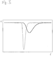
- Fig. 3 a diagram with a magnetic counter-pulse, which, driven by the control device 4, is generated by the electromagnet 2.
- the diagram shows the time t on the horizontal axis and the measurement signals on the vertical axis which correspond to the amount of deflection s of the load cell 1 due to the counter-pulse of the magnet.
- a thin line shows an unfiltered measurement of the displacement s caused by the magnetic counter-pulse
- a thick line shows the filtered measurement signal of the displacement s due to the magnetic counter-pulse.
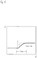
- Fig. 4 a diagram is shown with the superimposed with the magnetic counter-pulse transient signal.
- the thin line shows a graph of the in Fig. 2 shown as a thin line measurement signal with unfiltered ADC values of the load cell 1 due to the impact pulse from the in Fig. 3 shown as a thin line measured value of the load cell 1 due to the magnetic counter-pulse is superimposed.
- the thin line also shows the unfiltered measuring signal.
- the thick line showing the filtered measurement signal in contrast to the in Fig. 2 No overshoot on and earlier indicates a static end value, with a duration Twm until settling to the static final value smaller than the duration Tw in the Fig. 2 shown case.
- control device 4 is formed in one embodiment, in addition to the detection of the measurement signal of the load cell 1 and the control of the electromagnet 2, also to control a flow of an entire, not shown, scale.
- a triggering of falling objects to be weighed so a start of falling on the load cell 1 and in the container is controlled and a trigger signal for the beginning of the fall of an object to be weighed is generated.
- the scale is provided with a separate overall control device, which is then connected to the control device 4, and which also supplies the triggering signal for the start of falling object to be weighed to the control device 4, the control device 4 then detecting this triggering signal ,
- the control device 4 is formed in these two embodiments, in which the trigger signal for the start of the fall of the object to be weighed or detected is formed, in response to the trigger signal for the start of falling of the object to be weighed to control the electromagnet 2, that a magnetic counter-pulse with the force F S is generated on the load cell 1.
- the rigidity of the weighing cell 1 is increased and the weighing cell 1 is biased, as it were, before the objects to be weighed fall onto the weighing cell 1.
- the deflection of the load cell 1 may be smaller when the objects to be weighed are hit, and deflection over a predetermined limit set in advance may be prevented, for example.
- the load cell 1 is not biased before the impact of the objects to be weighed, but by a delayed actuation of the counter-pulse is an excessive deflection, with which the risk of damage is prevented or reduced only during the impact pulse, wherein the swinging of the load cell is also immediately suppressed.
- the impact pulse on the load cell 1 is detected by the load cell 1 and passed a corresponding signal to the control device 4.
- the control device 4 is adapted here to actuate the electromagnet 2 as a function of the measurement signal resulting from the impact pulse received by the weighing cell 1.
- the magnetic counter-pulse is to be generated as directly as possible after the impact of the objects to be weighed in order to prevent a large deflection of the load cell 1, which is suitable in Fig. 2 For this reason, in this case, to drive the electromagnet 2, the unfiltered signal is used to directly start the magnetic counter-pulse.
- the weighing device has a separate sensor 6, which detects the deflection, ie also a beginning of the deflection, of the weighing cell 1.
- the sensor 6 is designed as an acceleration sensor or a position sensor.
- the electromagnet 2 with an inductance measuring device can serve as a position sensor.
- a residual air gap of the electromagnet 2 increases, which then results in a reduction of the measured inductance Has. Thereby, the position of the armature 3 and thus the deflection of the load cell 1 can be detected.
- the sensor 6 is also connected to the control device 4. A signal of the sensor 6 is evaluated by the control device 4, whereby both the beginning of the deflection of the load cell 1 and the course of the deflection can be determined.
- An output signal of the control device 4 generated for driving the electromagnet 2 is dependent on the parameters "time of the force pulse” (starting time) and “duration of the force pulse” (operating time).
- the “moment of the momentum” depends on the time of the beginning of the free fall of the objects, the fall height and the local acceleration due to gravity.
- the “duration of the force pulse” (activation time) depends on the height of the impact pulse, which in turn depends on the mass, the fall height, the local acceleration due to gravity and on product properties.
- the control device 4 is provided in all embodiments with means for calculating and / or setting the various respectively required parameters.
- the control device 4 is also optionally configured to reduce vibrations of the weighing cell 1.
- the vibrations can be a vibration that is not or not completely damped due to the impact impulse, or can be impressed by external sources of interference. These sources of interference may be, for example, mechanical fluctuations of the ground by motors, conveyor systems, or the like, or electrical influences by mains frequencies or frequency-controlled drives. However, low-frequency oscillations can be caused by low-pass filters be reliably suppressed by measuring arrangements. At a correspondingly high data rate, the control device 4 can determine extreme values of these oscillations accurately and, taking account of the phase shift via the electromagnet 2, output magnetic counterpulses which reduce the deflection of the weighing cell 1. The parameters (start time, actuation time) are recalculated, depending on the current state of the weighing cell 1.
- the control device 4 In the methods in which the load cell 1 is biased before the impact pulse or during the impact pulse of the object to be weighed, the control device 4, or optionally the overall control device, first outputs the trigger signal for the start of the fall of the body to be weighed, or optionally recorded.
- the control device 4 thus knows the time of the beginning of the free fall itself or optionally detects it from the overall control device.
- start timing a pulse-shaped output signal is given to the solenoid 2 for a predetermined period (operation time) by the control device to increase the rigidity of the load cell 1.
- the starting time is determined depending on the height of the fall and the local acceleration due to gravity.
- the electromagnet 2 is controlled at the start time by the control device 4 so that the magnetic counter-pulse biases the load cell 1, whereby it has a higher rigidity than without magnetic counter-pulse before or during the weighing Object exerts the impact pulse on the load cell 1.
- the duration of the magnetic counter-pulse is determined as a function of the height of the impact pulse, which results from the mass, the height of fall and product properties of the object to be weighed and the local acceleration due to gravity.
- the measurement signal of the load cell 1 becomes before the output of the pulse-shaped output signal by the control device 4 detected on the basis of the impact pulse. From an analysis of the measurement signal, the height of the impact pulse is determined by the control device 4, the parameter of the duration of the force pulse is determined and immediately outputted a corresponding output signal as a single pulse signal for the counter-pulse to the electromagnet 2.
- the load cell is not deflected so much in this method, and also overshoots in the measurement signal and the time until a constant measurement signal is present, are reduced.
- a method to reduce the time until a constant measurement signal is present even after a decay of the impact pulse of an object to be weighed during a swing of the load cell 1 periodic pulses are detected.
- Fig. 5 is shown, at a zero crossing of the vibration shown with a thick line, ie of periodic pulses, in each case in the same phase by the electromagnet 2 is given a shown with a dash-dot line periodic antiphase pulse to the load cell 1.
- Each of these counter-pulses then reduces the amplitude of the oscillation so that, compared to the undamped oscillation shown with the thin line, the time until a constant measuring signal is present is reduced.
- the parameters of the periodic pulses are either determined in advance, or optionally calculated at each pulse received.
- the parameters of a parameter set are optionally varied within a predetermined probability range, namely a predetermined value range, and a corresponding output signal is given to the electromagnet 2.
- the effect of the individual parameter sets on the current measurement signal is detected and the output signal with the parameters of the parameter set with the effect that the vibration is attenuated amplified so that a constant measurement signal is output as quickly as possible, is output to the electromagnet 4.
- optimal parameters are determined in order to achieve an adaptive adaptation to changed conditions, whereby the weighing device is self-learning in order to optimally damp the oscillation of the weighing cell 1.
Landscapes
- Physics & Mathematics (AREA)
- General Physics & Mathematics (AREA)
- Electromagnetism (AREA)
- Weight Measurement For Supplying Or Discharging Of Specified Amounts Of Material (AREA)
- Measurement Of Force In General (AREA)
Description
- Die Erfindung betrifft eine Wägevorrichtung und ein Verfahren zum Betreiben der Wägevorrichtung, insbesondere eine Wägevorrichtung und ein Verfahren zum Wiegen von auf die Wägevorrichtung fallenden Objekten.
- Wenn Objekte, beispielsweise als Schüttgut, aus einer bestimmten Fallhöhe auf eine Wägezelle bzw. in damit verbundene Behälter fallen, entsteht ein Aufprallimpuls.
- Durch diesen Aufprallimpuls wird auf die Wägezelle eine Aufprallenergie übertragen. Diese Aufprallenergie kann, verglichen mit einer Auslenkung durch das statische Gewicht der Objekte, die Wägezelle um ein Vielfaches davon auslenken. Dadurch kann die Wägezelle beschädigt werden oder die Genauigkeit davon reduziert werden.
- Des Weiteren muss die in die Wägezelle übertragene Aufprallenergie abgebaut werden. Dabei wird die Wägezelle entsprechend ihrer Eigenfrequenz in Schwingungen versetzt und die Aufprallenergie beispielsweise durch innere Reibung in Wärme umgesetzt. Da durch die Schwingungen aber kein konstantes Messsignal der Wägezelle, das das Gewicht der Objekte auf der Wägezelle oder in dem Behälter angibt, möglich ist, dauert das Erfassen des tatsächlichen Gewichts des Objekts erheblich länger als bei einem Objekt, das auf die Wägezelle oder in den Behälter gelegt wird.
- Als Abhilfemaßnahme gegen die übermäßige Verformung und das Schwingen werden mechanische Bauteile, wie etwa Anschläge, oder Dämpfer auf pneumatischem Wirkprinzip, mit Öl oder als Elastomer oder Drahtkissen verwendet, was aber aufwändig ist und einen erhöhten Bauraum beansprucht. Weitere Möglichkeiten sind, die Signale durch Analogfilter oder Digitalfilter zusätzlich zu filtern, um hochfrequente Schwingungen zu eliminieren, was aber niederfrequente Schwingungen nicht herausfiltert, so dass die Zeit zum Erfassen des tatsächlichen Gewichts nicht reduziert wird.
Aus dem Stand der Technik ist das DokumentGB 229 831 A
Des Weiteren ist das DokumentGB 684 475 A - Weiterer Stand der Technik ist durch Dokument
US 5 850 057 A gegeben. - Es ist die Aufgabe der Erfindung, die obigen Nachteile auszuräumen und eine einfache, kostengünstige Lösung mit geringer Bauhöhe, die auch nachrüstbar ist, sowohl für eine Reduzierung der Auslenkung der Wägezelle auf Grund des Aufprallimpulses als auch für eine Schwingungsdämpfung bereitzustellen.
- Die Aufgabe wird durch eine Wägevorrichtung mit den Merkmalen des Anspruchs 1 und eine Kombinationswaage gemäß Anspruch 13 gelöst. Ein Verfahren zum Lösen der Aufgabe ist in Anspruch 7 angegeben. Weiterentwicklungen der Erfindung sind Gegenstand der abhängigen Ansprüche.
- In der Wägevorrichtung mit den Merkmalen des Anspruchs 1 wird eine Steifigkeit einer Wägezelle erhöht, so dass die Wägezelle als Anschlag dienen kann. Darüber hinaus ist ein Elektromagnet so ansteuerbar, dass die Steifigkeit der Wägezelle durch eine Steuerungsvorrichtung so gesteuert eingestellt werden kann, dass Schwingungen der Wägezelle schnell und effektiv gedämpft werden können.
- Die Erfindung wird nun anhand von Ausführungsbeispielen unter Bezugnahme auf die beigefügten Zeichnungen erläutert.
- Insbesondere zeigen
- Fig.1
- eine Baugruppe aus einer Wägezelle mit einem damit verbundenen Anker und einem separat befestigten Elektromagneten;
- Fig. 2
- ein Diagramm mit einem Einschwingsignal;
- Fig. 3
- ein Diagramm mit einem magnetischen Gegenimpuls;
- Fig. 4
- ein Diagramm mit einem mit einem magnetischen Gegenimpuls überlagerten Einschwingsignal; und
- Fig. 5
- ein Diagramm mit einem Verlauf einer Schwingungsdämpfung.
-
Fig. 1 zeigt eine Baugruppe, bestehend aus einer Wägezelle 1 und einem Elektromagneten 2, die in eine Kombinationswaage eingebaut ist. Die Wägezelle 1 und der Elektromagnet 2 sind separat an einem symbolisch gezeigten Gehäuse einer Wägevorrichtung befestigt. Zum Zusammenwirken mit dem Elektromagneten 2 weist die Baugruppe einen Anker 3 auf, der in die Wägezelle 1 integriert ist. Alternativ ist der Anker 3 nicht in die Wägezelle 1 integriert, sondern in einer anderen Weise, etwa darauf aufgesetzt, mit ihr verbunden. - Der Elektromagnet 2 ist optional mit einer Topfspule oder einer Tauchspule versehen.
- Bei einer Belastung der Wägezelle 1 durch ein zu wiegendes Objekt wird auf die Wägezelle 1, optional über einen an der Wägezelle 1 befestigten Behälter zum Aufnehmen der zu wiegenden Objekte, eine Kraft FG ausgeübt. Die Kraft FG entspricht bei einer statischen Last der Gewichtskraft der zu wiegenden Objekte. Bei einer dynamischen Last, beispielsweise beim Aufprallen der zu wiegenden Objekte, die auf die Wägezelle 1 fallen, entspricht sie einem Aufprallimpuls.
- Durch das Zusammenwirken des Elektromagneten 2 und des Ankers 3 wirkt, sobald der Elektromagnet 2 erregt ist, zwischen dem Elektromagneten 2 und dem Anker 3 eine Kraft FS. Durch die Kraft Fs wirkt auf das in
Fig. 1 rechts dargestellte Ende der Wägezelle 1 die Kraft Fs nach oben, also entgegengesetzt zu der inFig. 1 nach unten gerichteten Gewichtskraft FG und wirkt somit als Gegenkraft bzw. magnetischer Gegenimpuls. - Die Steifigkeit eines Körpers wird dabei als Widerstand gegen eine elastische Verformung, die auf Grund der Kraft FG hervorgerufen wird, definiert. Beim Aufbringen der Kraft FG auf die Wägezelle 1 verformt sich diese in Abhängigkeit von ihrer inhärenten Steifigkeit um ein bestimmtes Ausmaß. Wenn nun zusätzlich die Gegenkraft FS entgegengesetzt zu der Kraft FG aufgebracht wird, wird die Steifigkeit der Wägezelle 1 erhöht und die Wägezelle 1 nicht mehr so stark ausgelenkt. Eine Erhöhung der Steifigkeit der Wägezelle 1 verringert folglich die Auswirkung einer auf die Wägezelle 1 wirkenden Kraft FG.
- Optional ist der Elektromagnet 2 in einem vorbestimmten Abstand, beispielsweise von ca. 0,3 mm, angeordnet, so dass der Elektromagnet 2 bei einer übermäßigen Verformung der Wägezelle 1 für den Anker 3 als Anschlag dienen kann.
- Die Wägezelle 1 ist hier mit Dehnmessstreifen 5 versehen, um über eine Verformung des elastischen Körpers der Wägezelle 1 eine Kraft FG zu erfassen. Optional kann die Verformung auch mit anderen Mitteln, wie etwa optischen Mitteln oder induktiven Mitteln erfasst werden.
- Ferner ist eine Steuerungsvorrichtung 4 in der Baugruppe vorgesehen und mit der Wägezelle 1 verbunden, um von der Wägezelle 1 ausgegebene Messsignale zu erfassen. Die Steuerungsvorrichtung 4 ist ebenfalls mit dem Elektromagneten 2 verbunden und steuert diesen an.
- Die Steuerungsvorrichtung 4 ist dazu angepasst, das erfasste Messsignal der Wägezelle 1 auszuwerten. Das Messsignal der Wägezelle 1 gibt an, ob sich die Wägezelle 1 verformt, also ausgelenkt wird, und gibt somit in Verbindung mit der Steifigkeit der Wägezelle 1 eine auf die Wägezelle 1 wirkende Kraft an. Ohne die durch den Elektromagneten 2 erzeugte Kraft FG gibt das Messsignal in einem stationären Zustand der Auslenkung der Wägezelle 1, also bei einem konstanten Messsignal, die Kraft FG als die Gewichtskraft der zu wiegenden Objekte an. Sofern sich das Signal verändert, gibt das Messsignal an, dass ein Objekt einen Aufprallimpuls auf die Wägezelle 1 ausübt, oder dass die Auslenkung der Wägezelle 1 schwingt.
- Nachfolgend wird ein Effekt einer Überlagerung des Aufprallimpulses und des magnetischen Gegenimpulses erläutert.
- In
Fig. 2 ist ein Diagramm mit einem Einschwingsignal gezeigt. Das Diagramm zeigt auf der horizontalen Achse eine Zeit t und auf einer vertikalen Achse die Messsignale, die der Auslenkung s der Wägezelle 1 entsprechen. Dabei zeigt eine dünne Linie ein Messsignal mit ungefilterten ADC-Werten der Wägezelle bei einem Aufprallimpuls, wobei bei den ungefilterten Werten ein schneller Anstieg mit einem hohen Überschwinger vorliegt. Eine dicke Linie zeigt ein gefiltertes Messsignal. Es ist ersichtlich, dass das gefilterte Messsignal verzögert ist und eine kleinere Auslenkung anzeigt. Die Dauer für ein Einpendeln auf einen statischen Endwert ist mit Tw angegeben. Die Messsignale ergeben sich für eine Wägezelle 1, die entweder nicht mit einem Anker 3 versehen ist, oder bei der der Elektromagnet 2 nicht aktiviert ist. - In
Fig. 3 ist ein Diagramm mit einem magnetischen Gegenimpuls gezeigt, der, angesteuert durch die Steuerungsvorrichtung 4, durch den Elektromagneten 2 erzeugt wird. Das Diagramm zeigt auf der horizontalen Achse die Zeit t, und auf der vertikalen Achse die Messsignale, die dem Ausmaß der Auslenkung s der Wägezelle 1 auf Grund des Gegenimpulses des Magneten entsprechen. Hierbei zeigt eine dünne Linie einen ungefilterten Messwert der Auslenkung s, die durch den magnetischen Gegenimpuls hervorgerufen wird, und eine dicke Linie zeigt das gefilterte Messsignal der Auslenkung s auf Grund des magnetischen Gegenimpulses. - In
Fig. 4 ist ein Diagramm mit dem mit dem magnetischen Gegenimpuls überlagerten Einschwingsignal gezeigt. Die dünne Linie zeigt einen Graphen des inFig. 2 als dünne Linie dargestellten Messsignals mit ungefilterten ADC-Werten der Wägezelle 1 auf Grund des Aufprallimpulses, der von dem inFig. 3 als dünne Linie dargestellten Messwert der Wägezelle 1 auf Grund des magnetischen Gegenimpulses überlagert ist. Die dünne Linie zeigt auch hier das ungefilterte Messsignal. Im Vergleich zu dem inFig. 2 gezeigten Verlauf des ungefilterten Messsignals auf Grund des Aufprallimpulses ist zu erkennen, dass hier der Überschwinger wesentlich geringer ist und die Wägezelle 1 also wesentlich weniger ausgelenkt wird. Die dicke Linie, die das gefilterte Messsignal zeigt, weist im Gegensatz zu der inFig. 2 keinen Überschwinger mehr auf und gibt früher einen statischen Endwert an, wobei eine Dauer Twm bis zum Einpendeln auf den statischen Endwert kleiner als die Dauer Tw in demFig. 2 gezeigten Fall ist. - Die in
Fig. 1 gezeigte Steuerungsvorrichtung 4 ist in einer Ausführungsform dazu ausgebildet, neben der Erfassung des Messsignals der Wägezelle 1 und der Ansteuerung des Elektromagneten 2, auch einen Ablauf einer gesamten, nicht gezeigten, Waage zu steuern. Hierbei wird u.a. auch ein Auslösen eines Herabfallens von zu wiegenden Objekten, also ein Beginn des Herabfallens auf die Wägezelle 1 bzw. in den Behälter gesteuert und ein Auslösesignal für den Beginn des Herabfallens eines zu wiegenden Objekts wird erzeugt. - In einer alternativen Ausführungsform ist die Waage mit einer separaten Gesamtsteuerungsvorrichtung versehen, die dann mit der Steuerungsvorrichtung 4 verbunden ist, und die das Auslösesignal für den Beginn des Herabfallens eines zu wiegenden Objekts auch an die Steuerungsvorrichtung 4 liefert, wobei die Steuerungsvorrichtung 4 dann dieses Auslösesignal erfasst.
- Die Steuerungsvorrichtung 4 ist in diesen beiden Ausführungsformen, in denen das Auslösesignal für den Beginn des Herabfallens des zu wiegenden Objekts erzeugt oder erfasst wird, ausgebildet, in Abhängigkeit von dem Auslösesignal für den Beginn des Herabfallens des zu wiegenden Objekts, den Elektromagneten 2 so anzusteuern, dass ein magnetischer Gegenimpuls mit der Kraft FS auf die Wägezelle 1 erzeugt wird. Dadurch wird die Steifigkeit der Wägezelle 1 erhöht und die Wägezelle 1 quasi vorgespannt, bevor die zu wiegenden Objekte auf die Wägezelle 1 fallen. Somit kann die Auslenkung der Wägezelle 1 bei einem Auftreffen der zu wiegenden Objekte geringer ausfallen und eine Auslenkung über einen vorbestimmten Grenzwert, der im Voraus festgelegt wird, kann dadurch beispielsweise verhindert werden.
- In einer weiteren alternativen Ausführungsform wird die Wägezelle 1 nicht vor dem Aufprall der zu wiegenden Objekte vorgespannt, sondern durch eine verzögerte Ansteuerung des Gegenimpulses wird eine übermäßige Auslenkung, mit der die Beschädigungsgefahr einhergeht, erst während des Aufprallimpulses verhindert oder reduziert, wobei das Schwingen der Wägezelle ebenfalls unmittelbar unterdrückt wird.
- Der Aufprallimpuls auf die Wägezelle 1 wird durch die Wägezelle 1 erfasst und ein entsprechendes Signal an die Steuerungsvorrichtung 4 weitergegeben. Die Steuerungsvorrichtung 4 ist hier angepasst, in Abhängigkeit des sich auf Grund des von der Wägezelle 1 aufgenommenen Aufprallimpulses ergebenden Messsignals den Elektromagneten 2 anzusteuern.
- Da der magnetische Gegenimpuls möglichst unmittelbar nach dem Aufprallen der zu wiegenden Objekte erzeugt werden soll, um eine große Auslenkung der Wägezelle 1 zu verhindern, eignet sich das in
Fig. 2 gezeigte gefilterte Signal nicht als Basis für die Ansteuerung des Elektromagneten 2 für eine Erhöhung der Steifigkeit der Wägezelle 1. Aus diesem Grund wird in diesem Fall zur Ansteuerung des Elektromagneten 2 das ungefilterte Signal verwendet, um den magnetischen Gegenimpuls unmittelbar zu starten. - Optional weist die Wägevorrichtung einen separaten Sensor 6 auf, der die Auslenkung, also auch einen Beginn der Auslenkung, der Wägezelle 1 erfasst. Der Sensor 6 ist als ein Beschleunigungssensor oder ein Positionssensor ausgebildet. Alternativ kann auch der Elektromagnet 2 mit einer Induktivitätsmesseinrichtung als Positionssensor dienen. Bei einer Auslenkung der Wägezelle 1 vergrößert sich ein Restluftspalt des Elektromagneten 2, was dann eine Verringerung der gemessenen Induktivität zur Folge hat. Dadurch kann die Position des Ankers 3 und somit die Auslenkung der Wägezelle 1 erfasst werden.
- Der Sensor 6 ist ebenfalls mit der Steuerungsvorrichtung 4 verbunden. Ein Signal des Sensors 6 wird durch die Steuerungsvorrichtung 4 ausgewertet, wodurch sowohl der Beginn der Auslenkung der Wägezelle 1 als auch der Verlauf der Auslenkung bestimmt werden kann.
- Ein zur Ansteuerung des Elektromagneten 2 erzeugtes Ausgangssignal der Steuerungsvorrichtung 4 ist von den Parametern "Zeitpunkt des Kraftimpulses" (Startzeitpunkt) und "Dauer des Kraftimpulses" (Betätigungszeit) abhängig. Der "Zeitpunkt des Kraftimpulses" richtet sich nach dem Zeitpunkt des Beginns des freien Falls von den Objekten, der Fallhöhe und der örtlichen Erdbeschleunigung. Die "Dauer des Kraftimpulses" (Betätigungszeit) richtet sich nach der Höhe des Aufprallimpulses, welche wiederum von der Masse, der Fallhöhe, der örtlichen Erdbeschleunigung und von Produkteigenschaften abhängig ist.
- Die Steuerungsvorrichtung 4 ist in sämtlichen Ausführungsformen mit Mitteln zum Berechnen und/oder Festlegen der verschiedenen jeweils erforderlichen Parameter versehen.
- Die Steuerungsvorrichtung 4 ist ferner optional ausgebildet, Schwingungen der Wägezelle 1 zu verringern. Die Schwingungen können eine nicht oder nicht vollständig gedämpfte Schwingung auf Grund des Aufprallimpulses sein, oder durch externe Störquellen eingeprägt werden. Diese Störquellen können beispielsweise mechanische Schwankungen des Untergrunds durch Motoren, Fördersysteme, o.ä., oder elektrische Einflüsse durch Netzfrequenzen oder frequenzgeregelte Antriebe sein. Dabei entstehende niederfrequente Schwingungen können jedoch durch Tiefpassfilter von Messanordnungen nicht zuverlässig unterdrückt werden. Bei einer entsprechend hohen Datenrate kann die Steuerungsvorrichtung 4 Extremwerte dieser Schwingungen genau ermitteln und unter Berücksichtigung der Phasenverschiebung über den Elektromagneten 2 magnetische Gegenimpulse ausgeben, die die Auslenkung der Wägezelle 1 reduzieren. Die Parameter (Startzeitpunkt, Betätigungszeit) werden dabei, in Abhängigkeit vom derzeitigen Zustand der Wägezelle 1, jeweils neu berechnet.
- Im Betrieb sind verschiedene Verfahren möglich, um sowohl eine Reduzierung der Auslenkung der Wägezelle 1 auf Grund des Aufprallimpulses als auch eine Schwingungsdämpfung zu realisieren.
- In den Verfahren, in denen die Wägezelle 1 vor dem Aufprallimpuls oder während des Aufprallimpulses des zu wiegenden Objekts vorgespannt wird, wird von der Steuerungsvorrichtung 4, oder optional von der Gesamtsteuerungsvorrichtung, zunächst das Auslösesignal für den Beginn des Herabfallens des zu wiegenden Körpers ausgegeben, oder optional erfasst. Die Steuerungsvorrichtung 4 kennt also den Zeitpunkt des Beginns des freien Falls selbst oder erfasst ihn optional von der Gesamtsteuerungsvorrichtung. Zu einem vorbestimmten Zeitpunkt (Startzeitpunkt) wird für eine vorbestimmte Zeitdauer (Betätigungszeit) von der Steuerungsvorrichtung ein impulsförmiges Ausgangssignal an den Elektromagneten 2 gegeben, um die Steifigkeit der Wägezelle 1 zu erhöhen.
- Der Startzeitpunkt wird in Abhängigkeit von der Fallhöhe und der örtlichen Erdbeschleunigung festgelegt. Der Elektromagnet 2 wird zum Startzeitpunkt durch die Steuerungsvorrichtung 4 so angesteuert, dass der magnetische Gegenimpuls die Wägezelle 1 vorspannt, wodurch sie eine höhere Steifigkeit als ohne magnetischen Gegenimpuls aufweist, bevor oder während das zu wiegende Objekt den Aufprallimpuls auf die Wägezelle 1 ausübt. Die Dauer des magnetischen Gegenimpulses wird in Abhängigkeit von der Höhe des Aufprallimpulses festgelegt, der sich aus der Masse, der Fallhöhe und von Produkteigenschaften des zu wiegenden Objekts und der örtlichen Erdbeschleunigung ergibt.
- In diesen Verfahren wird die Wägezelle bei dem Aufprallimpuls der zu messenden Objekte auf die Wägezelle 1 oder den damit verbundenen Behälter, wie in
Fig. 4 im Vergleich zuFig. 2 gezeigt, auf Grund des Gegenimpulses nicht so stark ausgelenkt. In dem Messsignal entsteht kein Überschwinger und die Zeitdauer, bis ein konstantes Messsignal vorliegt ist kürzer. - In einem alternativen Verfahren, in dem nicht der Zeitpunkt des Beginns des freien Falls des zu wiegenden Objekts berücksichtigt wird, um die Auslenkung der Wägezelle auf Grund des Aufprallimpulses zu reduzieren, wird vor der Ausgabe des impulsförmigen Ausgangssignals durch die Steuerungsvorrichtung 4 das Messsignal der Wägezelle 1 auf Grund des Aufprallimpulses erfasst. Aus einer Analyse des Messsignals wird durch die Steuerungsvorrichtung 4 die Höhe des Aufprallimpulses ermittelt, der Parameter der Dauer des Kraftimpulses festgelegt und unverzüglich ein entsprechendes Ausgangssignal als einzelnes Impulssignal für den Gegenimpuls an den Elektromagneten 2 ausgegeben.
- In Folge des Aufprallimpulses der zu messenden Objekte auf die Wägezelle 1 oder den damit verbundenen Behälter wird auch in diesem Verfahren die Wägezelle nicht so stark ausgelenkt, und auch Überschwinger in dem Messsignal und die Zeitdauer, bis ein konstantes Messsignal vorliegt, werden reduziert.
- In einem weiteren alternativen Verfahren wird nicht das Messsignal der Wägezelle 1, sondern das Signal des Sensors 6, der die Auslenkung der Wägezelle 1 erfasst, erfasst. Das Verfahren entspricht ansonsten dem vorgenannten.
- Darüber hinaus werden in einem Verfahren, um die Zeitdauer zu reduzieren bis ein konstantes Messsignal vorliegt, auch nach einem Abklingen des Aufprallimpulses eines zu wiegenden Objekts während eines Schwingens der Wägezelle 1 periodische Impulse erfasst. Wie in
Fig. 5 gezeigt, wird immer bei einem Nulldurchgang der mit einer dicken Linie gezeigten Schwingung, also von periodischen Impulsen, jeweils in der gleichen Phase durch den Elektromagneten 2 ein mit einer Strich-Punkt-Linie gezeigter periodischer gegenphasiger Impuls auf die Wägezelle 1 gegeben. Durch jeden dieser Gegenimpulse wird dann die Amplitude der Schwingung verringert, so dass, im Vergleich zu der mit der dünnen Linie gezeigten ungedämpften Schwingung, die Zeitdauer, bis ein konstantes Messsignal vorliegt, reduziert wird. - Die Parameter der periodischen Impulse werden entweder vorab bestimmt, oder optional bei jedem aufgenommenen Impuls berechnet.
- Die Parameter eines Parametersatzes werden optional innerhalb eines vorbestimmten Wahrscheinlichkeitsbereichs, nämlich eines vorbestimmten Wertebereichs, variiert und ein entsprechendes Ausgangssignal wird an den Elektromagneten 2 gegeben. Die Auswirkung der einzelnen Parametersätze auf das aktuelle Messsignal wird erfasst und das Ausgangssignal mit den Parametern des Parametersatzes mit der Auswirkung, dass die Schwingung verstärkt gedämpft wird, so dass möglichst rasch ein konstantes Messsignal ausgegeben wird, wird an den Elektromagneten 4 ausgegeben. Somit werden für bestimmte Kriterien optimale Parameter ermittelt, um eine lernfähige Anpassung an veränderte Verhältnisse zu erzielen, wodurch die Wägevorrichtung selbstlernend ist, um das Schwingen der Wägezelle 1 optimal zu dämpfen.
- Um den Betrieb des Elektromagneten 2 bei den entsprechenden Ausgangssignalen dauerhaft sicherzustellen, wird eine Remanenz des Elektromagneten durch gezieltes Umpolen gelöscht.
- Die verschiedenen Ausführungsformen sind kombinierbar.
Claims (13)
- Wägevorrichtung aus einer Wägezelle (1) und einem Elektromagneten (2) mit einem Anker (3), wobei der Anker (3) an der Wägezelle (1) befestigt ist, der Elektromagnet (2) separat befestigt ist, und der Elektromagnet (2) und der Anker (3) so angeordnet sind, dass bei einer Ansteuerung des Elektromagneten (2) eine magnetische Kraft auf den Anker (3) und dadurch auf die Wägezelle (1) ausgeübt wird, die einer Auslenkung während eines Wiegevorgangs entgegengesetzt ist und welche eine von einem Aufprallimpuls eines zu wiegenden Objekts stammende Auslenkung reduziert, dadurch gekennzeichnet, dass die Wägezelle (1) eine Steuerungsvorrichtung (4) aufweist, die so ausgebildet ist, dass in Abhängigkeit von einem Auslösesignal für den Beginn des Herabfallens des zu wiegenden Objekts der Elektromagnet (2) so angesteuert wird dass ein magnetischer Gegenimpuls mit einer Kraft (FS) auf die Wägezelle (1) erzeugt wird.
- Wägevorrichtung gemäß Anspruch 1, wobei der Elektromagnet (2) in einem solchen Abstand von dem Anker (3) angeordnet ist, dass der Elektromagnet (2) als Anschlag für den Anker (3) vorgesehen ist.
- Wägevorrichtung gemäß einem der Ansprüche 1 oder 2, wobei
die Wägevorrichtung einen Sensor (6) zum Erfassen einer Auslenkung der Wägezelle (1) aufweist. - Wägevorrichtung gemäß Anspruch 3, wobei
die Steuerungsvorrichtung (4) ausgebildet ist, in Abhängigkeit von der von dem Sensor (6) erfassten Auslenkung der Wägezelle (1) den Elektromagneten (2) anzusteuern. - Wägevorrichtung gemäß einem der Ansprüche 1 bis 4, wobei
die Steuerungsvorrichtung (4) ausgebildet ist, in Abhängigkeit von einem von der Wägezelle (1) aufgenommenen Messsignal den Elektromagneten (2) anzusteuern. - Wägevorrichtung gemäß einem der Ansprüche 1 bis 5, wobei die Steuerungsvorrichtung (4) Mittel zum Festlegen von Parametern, zumindest einer Betätigungszeit des Elektromagneten (2) und/oder eines Startzeitpunktes der Ansteuerung des Elektromagneten (2) aufweist.
- Verfahren zum Betreiben einer Wägevorrichtung gemäß einem der Ansprüche 1 bis 6, aufweisend den Schritt:Ausgeben eines impulsförmigen Ausgangssignals an den Elektromagneten (2) zu einem vorbestimmten Zeitpunkt und von einer vorbestimmten Zeitdauer.
- Verfahren gemäß Anspruch 7 mit der Wägevorrichtung gemäß Anspruch 1, mit einem zusätzlichen vorhergehenden Schritt:Erfassen des Signals des Beginns des Herabfallens des zu wiegenden Objekts durch die Steuerungsvorrichtung (4), um das impulsförmige Ausgangssignal vor einem Aufprallimpuls oder während eines Aufprallimpulses des zu wiegenden Objekts auf die Wägezelle (1) auszugeben.
- Verfahren gemäß Anspruch 7 mit der Wägevorrichtung gemäß Anspruch 5, mit einem zusätzlichen Schritt:Erfassen des Messsignals der Wägezelle (1) durch die Steuerungsvorrichtung (4) und Ausgeben des impulsförmigen Ausgangssignals basierend auf dem erfassten Messsignal.
- Verfahren gemäß Anspruch 9, wobei
die Steuerungsvorrichtung (4) auch nach Abklingen eines Aufprallimpulses eines zu wiegenden Objekts bei Schwankungen des Messsignals diese durch gegenphasige magnetische Impulse reduziert. - Verfahren gemäß einem der Ansprüche 7 bis 10 mit eine Wägevorrichtung gemäß Anspruch 6, wobei die Parameter eines Parametersatzes innerhalb eines vorbestimmten Wertebereichs variiert werden, die Auswirkungen auf das Messsignal erfasst werden und die für bestimmte Kriterien optimalen Parameter ermittelt werden, um eine lernfähige Anpassung an veränderte Verhältnisse zu erzielen.
- Verfahren gemäß einem der Ansprüche 7 bis 11, wobei die Remanenz des Elektromagneten durch gezieltes Umpolen gelöscht wird.
- Kombinationswaage mit einer Wägevorrichtung gemäß einem der Ansprüche 1 bis 6.
Priority Applications (3)
| Application Number | Priority Date | Filing Date | Title |
|---|---|---|---|
| EP14156187.8A EP2910914B1 (de) | 2014-02-21 | 2014-02-21 | Wägevorrichtung und Verfahren zum Betreiben der Wägevorrichtung |
| MX2015001988A MX2015001988A (es) | 2014-02-21 | 2015-02-13 | Dispositivo de pesaje y procedimiento para manejar el dispositivo de pesaje. |
| US14/627,292 US20150241266A1 (en) | 2014-02-21 | 2015-02-20 | Weighing apparatus and method for operating the weighing apparatus |
Applications Claiming Priority (1)
| Application Number | Priority Date | Filing Date | Title |
|---|---|---|---|
| EP14156187.8A EP2910914B1 (de) | 2014-02-21 | 2014-02-21 | Wägevorrichtung und Verfahren zum Betreiben der Wägevorrichtung |
Publications (2)
| Publication Number | Publication Date |
|---|---|
| EP2910914A1 EP2910914A1 (de) | 2015-08-26 |
| EP2910914B1 true EP2910914B1 (de) | 2018-01-31 |
Family
ID=50150645
Family Applications (1)
| Application Number | Title | Priority Date | Filing Date |
|---|---|---|---|
| EP14156187.8A Not-in-force EP2910914B1 (de) | 2014-02-21 | 2014-02-21 | Wägevorrichtung und Verfahren zum Betreiben der Wägevorrichtung |
Country Status (3)
| Country | Link |
|---|---|
| US (1) | US20150241266A1 (de) |
| EP (1) | EP2910914B1 (de) |
| MX (1) | MX2015001988A (de) |
Families Citing this family (6)
| Publication number | Priority date | Publication date | Assignee | Title |
|---|---|---|---|---|
| JP5839975B2 (ja) * | 2011-12-14 | 2016-01-06 | 株式会社エー・アンド・デイ | 計量装置 |
| JP7020136B2 (ja) * | 2018-01-23 | 2022-02-16 | ニプロ株式会社 | 荷重測定装置 |
| CN107978067A (zh) * | 2018-01-23 | 2018-05-01 | 吴玙璋 | 一种平台交互式废纸回收器及其废纸回收交互方法 |
| CN110426107B (zh) * | 2019-09-09 | 2024-08-13 | 苏州钮曼精密机电科技有限公司 | 一种称重装置及称重系统 |
| CN116670468A (zh) * | 2020-10-27 | 2023-08-29 | 巴西Tmd摩擦力有限公司 | 测量物体的物理参数的方法、机械设备和装置 |
| CN115523987A (zh) * | 2021-06-25 | 2022-12-27 | 梅特勒-托利多(常州)精密仪器有限公司 | 一种称重设备及其称重方法 |
Citations (1)
| Publication number | Priority date | Publication date | Assignee | Title |
|---|---|---|---|---|
| US5850057A (en) * | 1996-09-04 | 1998-12-15 | The University Of Akron | Electromagnetically controlled load cell |
Family Cites Families (15)
| Publication number | Priority date | Publication date | Assignee | Title |
|---|---|---|---|---|
| GB229831A (en) * | 1924-01-23 | 1925-03-05 | Henry Pooley & Son Ltd | An electrically operated braking device for use in connection with weighing apparatus |
| GB684475A (en) * | 1949-01-14 | 1952-12-17 | W & J George & Becker Ltd | Improvements relating to electro-magnetic damping devices |
| BE755017A (fr) * | 1969-08-21 | 1971-02-01 | Avery Ltd W & T | Perfectionnements apportes aux appareils indicateurs de charge |
| DE2722093C2 (de) * | 1977-05-16 | 1979-02-15 | Hartmut Dipl.-Phys. Dr. 6203 Hochheim Gruetzediek | Gewichts- und Kraftmeßeinrichtung |
| CH615749A5 (de) * | 1977-07-28 | 1980-02-15 | Wirth Gallo & Co | |
| US4121676A (en) * | 1977-12-12 | 1978-10-24 | Pitney-Bowes, Inc. | Method of reducing hysteresis in a spring scale |
| US4223358A (en) * | 1979-04-30 | 1980-09-16 | Sony Corporation | Method and apparatus for cancelling the remanent deflection in a _piezoceramic head support means of a video recorder |
| US4412298A (en) * | 1979-09-20 | 1983-10-25 | Pitney Bowes Inc. | Method for tracking creep and drift in a digital scale under full load |
| US4529050A (en) * | 1984-01-20 | 1985-07-16 | Package Machinery Co. | Combination weighing machine with adaptive signal correction |
| CH675158A5 (de) * | 1988-06-14 | 1990-08-31 | Mettler Toledo Ag | |
| JPH0363526A (ja) * | 1989-07-31 | 1991-03-19 | Shimadzu Corp | 電子天びん |
| US5270497A (en) * | 1991-03-22 | 1993-12-14 | Shimadzu Corporation | Electronic balance with PID circuit |
| US6414252B1 (en) * | 1998-11-16 | 2002-07-02 | Mettler-Toledo Gmbh | Calibration system for a weighing scale |
| US6797893B2 (en) * | 2002-06-28 | 2004-09-28 | Pitney Bowes Inc. | Method and scale system and transducer used in such scale system for rapidly determining weights of items such as mail pieces |
| GB0226111D0 (en) * | 2002-11-08 | 2002-12-18 | Delta Electrical Ltd | Residual current devices |
-
2014
- 2014-02-21 EP EP14156187.8A patent/EP2910914B1/de not_active Not-in-force
-
2015
- 2015-02-13 MX MX2015001988A patent/MX2015001988A/es not_active Application Discontinuation
- 2015-02-20 US US14/627,292 patent/US20150241266A1/en not_active Abandoned
Patent Citations (1)
| Publication number | Priority date | Publication date | Assignee | Title |
|---|---|---|---|---|
| US5850057A (en) * | 1996-09-04 | 1998-12-15 | The University Of Akron | Electromagnetically controlled load cell |
Also Published As
| Publication number | Publication date |
|---|---|
| US20150241266A1 (en) | 2015-08-27 |
| EP2910914A1 (de) | 2015-08-26 |
| MX2015001988A (es) | 2015-10-05 |
Similar Documents
| Publication | Publication Date | Title |
|---|---|---|
| EP2910914B1 (de) | Wägevorrichtung und Verfahren zum Betreiben der Wägevorrichtung | |
| DE19651362C1 (de) | Vorrichtung zur Überwachung eines vorbestimmten Füllstands in einem Behälter | |
| DE102011007393B3 (de) | Verfahren zur Detektion eines Düsenraumdrucks in einem Injektor und Einspritzsystem | |
| EP2158493A1 (de) | Verfahren und vorrichtung zur kalibrierung von beschleunigungs- und kraftsensoren | |
| EP3181944A1 (de) | Schwingungsisolator mit einer vertikal wirksamen pneumatischen feder | |
| WO2019011906A1 (de) | Bedieneinheit für ein gerät | |
| WO2017162586A1 (de) | Bedieneinheit für ein gerät, insbesondere für eine fahrzeugkomponente | |
| DE102018211029A1 (de) | Verfahren und Sensor zur Erkennung einer Bewegung eines metallischen Gegenstandes mit extrem geringem Stromverbrauch | |
| EP3455849B1 (de) | Aktives schwingungsabsorptionssystem zur absorption einer schwingung eines schwingenden elements sowie kraftfahrzeug mit dem aktiven schwingungsabsorptionssystem und verfahren zum betreiben des aktiven schwingungsabsorptionssystems | |
| DE102004025156B3 (de) | Verfahren zur Fehlerkorrektur eines Wegsensorsignals | |
| DE102014111193A1 (de) | Küchenmaschine mit einer Wägeeinrichtung | |
| DE102016219622A1 (de) | Verfahren zur Erkennung einer Prellbewegung eines Pedals | |
| DE102016005642B4 (de) | Bedienelement zum Erfassen einer manuellen Eingabe eines Benutzers in einem Kraftfahrzeug sowie Verfahren zum Betrieb eines solchen | |
| EP1289147A1 (de) | Fremderregte Näherungs-oder Anwesenheitsschalteranordnung | |
| DE4137695C2 (de) | Sensoranordnung zur Feststellung des Bewegungszustandes eines Rotors | |
| DE4327167C2 (de) | Verfahren und Vorrichtung zum Feststellen eines vorbestimmten Füllstandes in einem Behältnis | |
| EP3114268B1 (de) | Verfahren zum bestimmen eines beladungsgewichts eines schwingenden systems eines haushaltsgeräts zur pflege von wäschestücken und haushaltsgerät | |
| DE3516200A1 (de) | Verfahren zur fuellstandskontrolle und einrichtung zur durchfuehrung des verfahrens | |
| CH698384B1 (de) | Verfahren zum automatischen Aufziehen einer Uhr. | |
| DE102004048519A1 (de) | Antriebsregelung für ein Regalbediengerät | |
| EP1715309A1 (de) | Behälterwaage | |
| EP2425207B1 (de) | Vorrichtung und verfahren zur messung einer relativbewegung eines targets | |
| EP2291615B1 (de) | Induktiver sensor | |
| DE3743897C2 (de) | ||
| DE19912974A1 (de) | Dämpfungsvorrichtung und Aktuator hierfür |
Legal Events
| Date | Code | Title | Description |
|---|---|---|---|
| PUAI | Public reference made under article 153(3) epc to a published international application that has entered the european phase |
Free format text: ORIGINAL CODE: 0009012 |
|
| 17P | Request for examination filed |
Effective date: 20140221 |
|
| AK | Designated contracting states |
Kind code of ref document: A1 Designated state(s): AL AT BE BG CH CY CZ DE DK EE ES FI FR GB GR HR HU IE IS IT LI LT LU LV MC MK MT NL NO PL PT RO RS SE SI SK SM TR |
|
| AX | Request for extension of the european patent |
Extension state: BA ME |
|
| RBV | Designated contracting states (corrected) |
Designated state(s): AL AT BE BG CH CY CZ DE DK EE ES FI FR GB GR HR HU IE IS IT LI LT LU LV MC MK MT NL NO PL PT RO RS SE SI SK SM TR |
|
| RIC1 | Information provided on ipc code assigned before grant |
Ipc: G01G 7/04 20060101ALN20160715BHEP Ipc: G01G 23/02 20060101AFI20160715BHEP Ipc: G01G 23/10 20060101ALI20160715BHEP |
|
| 17Q | First examination report despatched |
Effective date: 20160819 |
|
| GRAP | Despatch of communication of intention to grant a patent |
Free format text: ORIGINAL CODE: EPIDOSNIGR1 |
|
| RIC1 | Information provided on ipc code assigned before grant |
Ipc: G01G 23/10 20060101ALI20170712BHEP Ipc: G01G 23/02 20060101AFI20170712BHEP Ipc: G01G 7/04 20060101ALN20170712BHEP |
|
| INTG | Intention to grant announced |
Effective date: 20170725 |
|
| RIC1 | Information provided on ipc code assigned before grant |
Ipc: G01G 23/02 20060101AFI20170714BHEP Ipc: G01G 7/04 20060101ALN20170714BHEP Ipc: G01G 23/10 20060101ALI20170714BHEP |
|
| GRAS | Grant fee paid |
Free format text: ORIGINAL CODE: EPIDOSNIGR3 |
|
| GRAJ | Information related to disapproval of communication of intention to grant by the applicant or resumption of examination proceedings by the epo deleted |
Free format text: ORIGINAL CODE: EPIDOSDIGR1 |
|
| GRAL | Information related to payment of fee for publishing/printing deleted |
Free format text: ORIGINAL CODE: EPIDOSDIGR3 |
|
| GRAR | Information related to intention to grant a patent recorded |
Free format text: ORIGINAL CODE: EPIDOSNIGR71 |
|
| INTC | Intention to grant announced (deleted) | ||
| GRAA | (expected) grant |
Free format text: ORIGINAL CODE: 0009210 |
|
| RIC1 | Information provided on ipc code assigned before grant |
Ipc: G01G 23/10 20060101ALI20171208BHEP Ipc: G01G 23/02 20060101AFI20171208BHEP Ipc: G01G 7/04 20060101ALN20171208BHEP |
|
| INTG | Intention to grant announced |
Effective date: 20171218 |
|
| AK | Designated contracting states |
Kind code of ref document: B1 Designated state(s): AL AT BE BG CH CY CZ DE DK EE ES FI FR GB GR HR HU IE IS IT LI LT LU LV MC MK MT NL NO PL PT RO RS SE SI SK SM TR |
|
| REG | Reference to a national code |
Ref country code: GB Ref legal event code: FG4D Free format text: NOT ENGLISH Ref country code: CH Ref legal event code: EP |
|
| REG | Reference to a national code |
Ref country code: AT Ref legal event code: REF Ref document number: 967808 Country of ref document: AT Kind code of ref document: T Effective date: 20180215 |
|
| REG | Reference to a national code |
Ref country code: IE Ref legal event code: FG4D Free format text: LANGUAGE OF EP DOCUMENT: GERMAN |
|
| REG | Reference to a national code |
Ref country code: DE Ref legal event code: R096 Ref document number: 502014007052 Country of ref document: DE |
|
| REG | Reference to a national code |
Ref country code: NL Ref legal event code: MP Effective date: 20180131 |
|
| REG | Reference to a national code |
Ref country code: LT Ref legal event code: MG4D |
|
| PG25 | Lapsed in a contracting state [announced via postgrant information from national office to epo] |
Ref country code: ES Free format text: LAPSE BECAUSE OF FAILURE TO SUBMIT A TRANSLATION OF THE DESCRIPTION OR TO PAY THE FEE WITHIN THE PRESCRIBED TIME-LIMIT Effective date: 20180131 Ref country code: NO Free format text: LAPSE BECAUSE OF FAILURE TO SUBMIT A TRANSLATION OF THE DESCRIPTION OR TO PAY THE FEE WITHIN THE PRESCRIBED TIME-LIMIT Effective date: 20180430 Ref country code: NL Free format text: LAPSE BECAUSE OF FAILURE TO SUBMIT A TRANSLATION OF THE DESCRIPTION OR TO PAY THE FEE WITHIN THE PRESCRIBED TIME-LIMIT Effective date: 20180131 Ref country code: LT Free format text: LAPSE BECAUSE OF FAILURE TO SUBMIT A TRANSLATION OF THE DESCRIPTION OR TO PAY THE FEE WITHIN THE PRESCRIBED TIME-LIMIT Effective date: 20180131 Ref country code: HR Free format text: LAPSE BECAUSE OF FAILURE TO SUBMIT A TRANSLATION OF THE DESCRIPTION OR TO PAY THE FEE WITHIN THE PRESCRIBED TIME-LIMIT Effective date: 20180131 Ref country code: FI Free format text: LAPSE BECAUSE OF FAILURE TO SUBMIT A TRANSLATION OF THE DESCRIPTION OR TO PAY THE FEE WITHIN THE PRESCRIBED TIME-LIMIT Effective date: 20180131 |
|
| PG25 | Lapsed in a contracting state [announced via postgrant information from national office to epo] |
Ref country code: GR Free format text: LAPSE BECAUSE OF FAILURE TO SUBMIT A TRANSLATION OF THE DESCRIPTION OR TO PAY THE FEE WITHIN THE PRESCRIBED TIME-LIMIT Effective date: 20180501 Ref country code: RS Free format text: LAPSE BECAUSE OF FAILURE TO SUBMIT A TRANSLATION OF THE DESCRIPTION OR TO PAY THE FEE WITHIN THE PRESCRIBED TIME-LIMIT Effective date: 20180131 Ref country code: PL Free format text: LAPSE BECAUSE OF FAILURE TO SUBMIT A TRANSLATION OF THE DESCRIPTION OR TO PAY THE FEE WITHIN THE PRESCRIBED TIME-LIMIT Effective date: 20180131 Ref country code: SE Free format text: LAPSE BECAUSE OF FAILURE TO SUBMIT A TRANSLATION OF THE DESCRIPTION OR TO PAY THE FEE WITHIN THE PRESCRIBED TIME-LIMIT Effective date: 20180131 Ref country code: LV Free format text: LAPSE BECAUSE OF FAILURE TO SUBMIT A TRANSLATION OF THE DESCRIPTION OR TO PAY THE FEE WITHIN THE PRESCRIBED TIME-LIMIT Effective date: 20180131 Ref country code: BG Free format text: LAPSE BECAUSE OF FAILURE TO SUBMIT A TRANSLATION OF THE DESCRIPTION OR TO PAY THE FEE WITHIN THE PRESCRIBED TIME-LIMIT Effective date: 20180430 Ref country code: IS Free format text: LAPSE BECAUSE OF FAILURE TO SUBMIT A TRANSLATION OF THE DESCRIPTION OR TO PAY THE FEE WITHIN THE PRESCRIBED TIME-LIMIT Effective date: 20180531 |
|
| REG | Reference to a national code |
Ref country code: CH Ref legal event code: PL |
|
| PG25 | Lapsed in a contracting state [announced via postgrant information from national office to epo] |
Ref country code: MT Free format text: LAPSE BECAUSE OF FAILURE TO SUBMIT A TRANSLATION OF THE DESCRIPTION OR TO PAY THE FEE WITHIN THE PRESCRIBED TIME-LIMIT Effective date: 20180131 |
|
| PG25 | Lapsed in a contracting state [announced via postgrant information from national office to epo] |
Ref country code: RO Free format text: LAPSE BECAUSE OF FAILURE TO SUBMIT A TRANSLATION OF THE DESCRIPTION OR TO PAY THE FEE WITHIN THE PRESCRIBED TIME-LIMIT Effective date: 20180131 Ref country code: AL Free format text: LAPSE BECAUSE OF FAILURE TO SUBMIT A TRANSLATION OF THE DESCRIPTION OR TO PAY THE FEE WITHIN THE PRESCRIBED TIME-LIMIT Effective date: 20180131 Ref country code: EE Free format text: LAPSE BECAUSE OF FAILURE TO SUBMIT A TRANSLATION OF THE DESCRIPTION OR TO PAY THE FEE WITHIN THE PRESCRIBED TIME-LIMIT Effective date: 20180131 Ref country code: IT Free format text: LAPSE BECAUSE OF FAILURE TO SUBMIT A TRANSLATION OF THE DESCRIPTION OR TO PAY THE FEE WITHIN THE PRESCRIBED TIME-LIMIT Effective date: 20180131 |
|
| REG | Reference to a national code |
Ref country code: DE Ref legal event code: R097 Ref document number: 502014007052 Country of ref document: DE |
|
| REG | Reference to a national code |
Ref country code: IE Ref legal event code: MM4A |
|
| REG | Reference to a national code |
Ref country code: BE Ref legal event code: MM Effective date: 20180228 |
|
| PG25 | Lapsed in a contracting state [announced via postgrant information from national office to epo] |
Ref country code: MC Free format text: LAPSE BECAUSE OF FAILURE TO SUBMIT A TRANSLATION OF THE DESCRIPTION OR TO PAY THE FEE WITHIN THE PRESCRIBED TIME-LIMIT Effective date: 20180131 Ref country code: DK Free format text: LAPSE BECAUSE OF FAILURE TO SUBMIT A TRANSLATION OF THE DESCRIPTION OR TO PAY THE FEE WITHIN THE PRESCRIBED TIME-LIMIT Effective date: 20180131 Ref country code: SM Free format text: LAPSE BECAUSE OF FAILURE TO SUBMIT A TRANSLATION OF THE DESCRIPTION OR TO PAY THE FEE WITHIN THE PRESCRIBED TIME-LIMIT Effective date: 20180131 Ref country code: SK Free format text: LAPSE BECAUSE OF FAILURE TO SUBMIT A TRANSLATION OF THE DESCRIPTION OR TO PAY THE FEE WITHIN THE PRESCRIBED TIME-LIMIT Effective date: 20180131 Ref country code: LU Free format text: LAPSE BECAUSE OF NON-PAYMENT OF DUE FEES Effective date: 20180221 Ref country code: CZ Free format text: LAPSE BECAUSE OF FAILURE TO SUBMIT A TRANSLATION OF THE DESCRIPTION OR TO PAY THE FEE WITHIN THE PRESCRIBED TIME-LIMIT Effective date: 20180131 Ref country code: CH Free format text: LAPSE BECAUSE OF NON-PAYMENT OF DUE FEES Effective date: 20180228 Ref country code: LI Free format text: LAPSE BECAUSE OF NON-PAYMENT OF DUE FEES Effective date: 20180228 |
|
| PLBE | No opposition filed within time limit |
Free format text: ORIGINAL CODE: 0009261 |
|
| STAA | Information on the status of an ep patent application or granted ep patent |
Free format text: STATUS: NO OPPOSITION FILED WITHIN TIME LIMIT |
|
| GBPC | Gb: european patent ceased through non-payment of renewal fee |
Effective date: 20180430 |
|
| 26N | No opposition filed |
Effective date: 20181102 |
|
| PG25 | Lapsed in a contracting state [announced via postgrant information from national office to epo] |
Ref country code: IE Free format text: LAPSE BECAUSE OF NON-PAYMENT OF DUE FEES Effective date: 20180221 |
|
| PG25 | Lapsed in a contracting state [announced via postgrant information from national office to epo] |
Ref country code: BE Free format text: LAPSE BECAUSE OF NON-PAYMENT OF DUE FEES Effective date: 20180228 Ref country code: GB Free format text: LAPSE BECAUSE OF NON-PAYMENT OF DUE FEES Effective date: 20180430 Ref country code: SI Free format text: LAPSE BECAUSE OF FAILURE TO SUBMIT A TRANSLATION OF THE DESCRIPTION OR TO PAY THE FEE WITHIN THE PRESCRIBED TIME-LIMIT Effective date: 20180131 |
|
| PG25 | Lapsed in a contracting state [announced via postgrant information from national office to epo] |
Ref country code: FR Free format text: LAPSE BECAUSE OF NON-PAYMENT OF DUE FEES Effective date: 20180331 |
|
| PGFP | Annual fee paid to national office [announced via postgrant information from national office to epo] |
Ref country code: DE Payment date: 20190225 Year of fee payment: 6 |
|
| PG25 | Lapsed in a contracting state [announced via postgrant information from national office to epo] |
Ref country code: TR Free format text: LAPSE BECAUSE OF FAILURE TO SUBMIT A TRANSLATION OF THE DESCRIPTION OR TO PAY THE FEE WITHIN THE PRESCRIBED TIME-LIMIT Effective date: 20180131 |
|
| REG | Reference to a national code |
Ref country code: AT Ref legal event code: MM01 Ref document number: 967808 Country of ref document: AT Kind code of ref document: T Effective date: 20190221 |
|
| PG25 | Lapsed in a contracting state [announced via postgrant information from national office to epo] |
Ref country code: AT Free format text: LAPSE BECAUSE OF NON-PAYMENT OF DUE FEES Effective date: 20190221 |
|
| PG25 | Lapsed in a contracting state [announced via postgrant information from national office to epo] |
Ref country code: PT Free format text: LAPSE BECAUSE OF FAILURE TO SUBMIT A TRANSLATION OF THE DESCRIPTION OR TO PAY THE FEE WITHIN THE PRESCRIBED TIME-LIMIT Effective date: 20180131 |
|
| PG25 | Lapsed in a contracting state [announced via postgrant information from national office to epo] |
Ref country code: HU Free format text: LAPSE BECAUSE OF FAILURE TO SUBMIT A TRANSLATION OF THE DESCRIPTION OR TO PAY THE FEE WITHIN THE PRESCRIBED TIME-LIMIT; INVALID AB INITIO Effective date: 20140221 Ref country code: CY Free format text: LAPSE BECAUSE OF FAILURE TO SUBMIT A TRANSLATION OF THE DESCRIPTION OR TO PAY THE FEE WITHIN THE PRESCRIBED TIME-LIMIT Effective date: 20180131 Ref country code: MK Free format text: LAPSE BECAUSE OF NON-PAYMENT OF DUE FEES Effective date: 20180131 |
|
| REG | Reference to a national code |
Ref country code: DE Ref legal event code: R119 Ref document number: 502014007052 Country of ref document: DE |
|
| PG25 | Lapsed in a contracting state [announced via postgrant information from national office to epo] |
Ref country code: DE Free format text: LAPSE BECAUSE OF NON-PAYMENT OF DUE FEES Effective date: 20200901 |