EP0505624A2 - Isozentrischer Einspritzer mit niedriger Turbulenz - Google Patents
Isozentrischer Einspritzer mit niedriger Turbulenz Download PDFInfo
- Publication number
- EP0505624A2 EP0505624A2 EP91122004A EP91122004A EP0505624A2 EP 0505624 A2 EP0505624 A2 EP 0505624A2 EP 91122004 A EP91122004 A EP 91122004A EP 91122004 A EP91122004 A EP 91122004A EP 0505624 A2 EP0505624 A2 EP 0505624A2
- Authority
- EP
- European Patent Office
- Prior art keywords
- fluid
- conduit
- flow
- fluids
- carbon dioxide
- Prior art date
- Legal status (The legal status is an assumption and is not a legal conclusion. Google has not performed a legal analysis and makes no representation as to the accuracy of the status listed.)
- Withdrawn
Links
- 239000012530 fluid Substances 0.000 claims abstract description 455
- 239000002904 solvent Substances 0.000 claims abstract description 120
- 239000007787 solid Substances 0.000 claims abstract description 88
- 238000000034 method Methods 0.000 claims abstract description 47
- 238000001556 precipitation Methods 0.000 claims abstract description 34
- CURLTUGMZLYLDI-UHFFFAOYSA-N Carbon dioxide Chemical compound O=C=O CURLTUGMZLYLDI-UHFFFAOYSA-N 0.000 description 282
- 239000008199 coating composition Substances 0.000 description 177
- 229910002092 carbon dioxide Inorganic materials 0.000 description 141
- 239000001569 carbon dioxide Substances 0.000 description 137
- 238000002156 mixing Methods 0.000 description 72
- 229920000642 polymer Polymers 0.000 description 72
- 239000000203 mixture Substances 0.000 description 51
- 239000007788 liquid Substances 0.000 description 41
- 239000003638 chemical reducing agent Substances 0.000 description 39
- 238000005507 spraying Methods 0.000 description 38
- 239000000463 material Substances 0.000 description 26
- 239000007921 spray Substances 0.000 description 24
- 229920005989 resin Polymers 0.000 description 22
- 239000011347 resin Substances 0.000 description 22
- 238000000576 coating method Methods 0.000 description 20
- 239000010408 film Substances 0.000 description 20
- 230000000717 retained effect Effects 0.000 description 20
- 230000015572 biosynthetic process Effects 0.000 description 18
- 230000003068 static effect Effects 0.000 description 18
- 238000002347 injection Methods 0.000 description 17
- 239000007924 injection Substances 0.000 description 17
- XLYOFNOQVPJJNP-UHFFFAOYSA-N water Substances O XLYOFNOQVPJJNP-UHFFFAOYSA-N 0.000 description 17
- 239000011248 coating agent Substances 0.000 description 16
- 239000002245 particle Substances 0.000 description 14
- 239000000020 Nitrocellulose Substances 0.000 description 13
- 229920001220 nitrocellulos Polymers 0.000 description 13
- 238000005086 pumping Methods 0.000 description 13
- 230000007704 transition Effects 0.000 description 13
- 230000000694 effects Effects 0.000 description 12
- -1 metallic flakes Substances 0.000 description 12
- 230000009471 action Effects 0.000 description 10
- 230000008878 coupling Effects 0.000 description 10
- 238000010168 coupling process Methods 0.000 description 10
- 238000005859 coupling reaction Methods 0.000 description 10
- 239000003921 oil Substances 0.000 description 10
- 238000009792 diffusion process Methods 0.000 description 9
- 230000033001 locomotion Effects 0.000 description 9
- 235000019198 oils Nutrition 0.000 description 9
- 150000001875 compounds Chemical class 0.000 description 8
- 239000011521 glass Substances 0.000 description 8
- 239000000243 solution Substances 0.000 description 8
- 239000000758 substrate Substances 0.000 description 8
- KFZMGEQAYNKOFK-UHFFFAOYSA-N Isopropanol Chemical compound CC(C)O KFZMGEQAYNKOFK-UHFFFAOYSA-N 0.000 description 7
- 229920000180 alkyd Polymers 0.000 description 7
- 230000008859 change Effects 0.000 description 7
- 238000010586 diagram Methods 0.000 description 7
- 239000007789 gas Substances 0.000 description 7
- OKKJLVBELUTLKV-UHFFFAOYSA-N Methanol Chemical compound OC OKKJLVBELUTLKV-UHFFFAOYSA-N 0.000 description 6
- 238000007689 inspection Methods 0.000 description 6
- 239000000049 pigment Substances 0.000 description 6
- POAOYUHQDCAZBD-UHFFFAOYSA-N 2-butoxyethanol Chemical compound CCCCOCCO POAOYUHQDCAZBD-UHFFFAOYSA-N 0.000 description 5
- 241000237858 Gastropoda Species 0.000 description 5
- 238000013461 design Methods 0.000 description 5
- LYCAIKOWRPUZTN-UHFFFAOYSA-N ethylene glycol Natural products OCCO LYCAIKOWRPUZTN-UHFFFAOYSA-N 0.000 description 5
- 238000002474 experimental method Methods 0.000 description 5
- 239000004922 lacquer Substances 0.000 description 5
- 239000003973 paint Substances 0.000 description 5
- 229920000728 polyester Polymers 0.000 description 5
- 239000002244 precipitate Substances 0.000 description 5
- 230000008569 process Effects 0.000 description 5
- 239000013598 vector Substances 0.000 description 5
- LFQSCWFLJHTTHZ-UHFFFAOYSA-N Ethanol Chemical compound CCO LFQSCWFLJHTTHZ-UHFFFAOYSA-N 0.000 description 4
- LRHPLDYGYMQRHN-UHFFFAOYSA-N N-Butanol Chemical compound CCCCO LRHPLDYGYMQRHN-UHFFFAOYSA-N 0.000 description 4
- 238000009826 distribution Methods 0.000 description 4
- 239000000499 gel Substances 0.000 description 4
- ZXEKIIBDNHEJCQ-UHFFFAOYSA-N isobutanol Chemical compound CC(C)CO ZXEKIIBDNHEJCQ-UHFFFAOYSA-N 0.000 description 4
- GQPLMRYTRLFLPF-UHFFFAOYSA-N nitrous oxide Inorganic materials [O-][N+]#N GQPLMRYTRLFLPF-UHFFFAOYSA-N 0.000 description 4
- 230000000704 physical effect Effects 0.000 description 4
- 239000000126 substance Substances 0.000 description 4
- RWNUSVWFHDHRCJ-UHFFFAOYSA-N 1-butoxypropan-2-ol Chemical compound CCCCOCC(C)O RWNUSVWFHDHRCJ-UHFFFAOYSA-N 0.000 description 3
- ZWEHNKRNPOVVGH-UHFFFAOYSA-N 2-Butanone Chemical compound CCC(C)=O ZWEHNKRNPOVVGH-UHFFFAOYSA-N 0.000 description 3
- ZNQVEEAIQZEUHB-UHFFFAOYSA-N 2-ethoxyethanol Chemical group CCOCCO ZNQVEEAIQZEUHB-UHFFFAOYSA-N 0.000 description 3
- YEYKMVJDLWJFOA-UHFFFAOYSA-N 2-propoxyethanol Chemical compound CCCOCCO YEYKMVJDLWJFOA-UHFFFAOYSA-N 0.000 description 3
- CSCPPACGZOOCGX-UHFFFAOYSA-N Acetone Chemical compound CC(C)=O CSCPPACGZOOCGX-UHFFFAOYSA-N 0.000 description 3
- XEKOWRVHYACXOJ-UHFFFAOYSA-N Ethyl acetate Chemical compound CCOC(C)=O XEKOWRVHYACXOJ-UHFFFAOYSA-N 0.000 description 3
- YXFVVABEGXRONW-UHFFFAOYSA-N Toluene Chemical compound CC1=CC=CC=C1 YXFVVABEGXRONW-UHFFFAOYSA-N 0.000 description 3
- NIXOWILDQLNWCW-UHFFFAOYSA-N acrylic acid group Chemical group C(C=C)(=O)O NIXOWILDQLNWCW-UHFFFAOYSA-N 0.000 description 3
- 239000000654 additive Substances 0.000 description 3
- 239000000853 adhesive Substances 0.000 description 3
- 230000001070 adhesive effect Effects 0.000 description 3
- 125000001931 aliphatic group Chemical group 0.000 description 3
- 230000008901 benefit Effects 0.000 description 3
- BTANRVKWQNVYAZ-UHFFFAOYSA-N butan-2-ol Chemical compound CCC(C)O BTANRVKWQNVYAZ-UHFFFAOYSA-N 0.000 description 3
- 230000001914 calming effect Effects 0.000 description 3
- 238000002485 combustion reaction Methods 0.000 description 3
- 230000001276 controlling effect Effects 0.000 description 3
- 230000001419 dependent effect Effects 0.000 description 3
- 230000008021 deposition Effects 0.000 description 3
- 238000011161 development Methods 0.000 description 3
- 239000003085 diluting agent Substances 0.000 description 3
- 238000004090 dissolution Methods 0.000 description 3
- 230000007613 environmental effect Effects 0.000 description 3
- 239000000446 fuel Substances 0.000 description 3
- 238000010438 heat treatment Methods 0.000 description 3
- CATSNJVOTSVZJV-UHFFFAOYSA-N heptan-2-one Chemical compound CCCCCC(C)=O CATSNJVOTSVZJV-UHFFFAOYSA-N 0.000 description 3
- 238000000265 homogenisation Methods 0.000 description 3
- 229930195733 hydrocarbon Natural products 0.000 description 3
- 150000002430 hydrocarbons Chemical class 0.000 description 3
- WGCNASOHLSPBMP-UHFFFAOYSA-N hydroxyacetaldehyde Natural products OCC=O WGCNASOHLSPBMP-UHFFFAOYSA-N 0.000 description 3
- 229960004592 isopropanol Drugs 0.000 description 3
- 238000005259 measurement Methods 0.000 description 3
- 230000007246 mechanism Effects 0.000 description 3
- 238000003801 milling Methods 0.000 description 3
- 239000003960 organic solvent Substances 0.000 description 3
- 238000012354 overpressurization Methods 0.000 description 3
- 229920002635 polyurethane Polymers 0.000 description 3
- 239000004814 polyurethane Substances 0.000 description 3
- 230000004044 response Effects 0.000 description 3
- 229910001220 stainless steel Inorganic materials 0.000 description 3
- 239000010935 stainless steel Substances 0.000 description 3
- 239000010409 thin film Substances 0.000 description 3
- FENFUOGYJVOCRY-UHFFFAOYSA-N 1-propoxypropan-2-ol Chemical compound CCCOCC(C)O FENFUOGYJVOCRY-UHFFFAOYSA-N 0.000 description 2
- IJGRMHOSHXDMSA-UHFFFAOYSA-N Atomic nitrogen Chemical compound N#N IJGRMHOSHXDMSA-UHFFFAOYSA-N 0.000 description 2
- 239000004215 Carbon black (E152) Substances 0.000 description 2
- XZMCDFZZKTWFGF-UHFFFAOYSA-N Cyanamide Chemical compound NC#N XZMCDFZZKTWFGF-UHFFFAOYSA-N 0.000 description 2
- SECXISVLQFMRJM-UHFFFAOYSA-N N-Methylpyrrolidone Chemical compound CN1CCCC1=O SECXISVLQFMRJM-UHFFFAOYSA-N 0.000 description 2
- OFBQJSOFQDEBGM-UHFFFAOYSA-N Pentane Chemical compound CCCCC OFBQJSOFQDEBGM-UHFFFAOYSA-N 0.000 description 2
- ATUOYWHBWRKTHZ-UHFFFAOYSA-N Propane Chemical compound CCC ATUOYWHBWRKTHZ-UHFFFAOYSA-N 0.000 description 2
- GWEVSGVZZGPLCZ-UHFFFAOYSA-N Titan oxide Chemical compound O=[Ti]=O GWEVSGVZZGPLCZ-UHFFFAOYSA-N 0.000 description 2
- 229920006397 acrylic thermoplastic Polymers 0.000 description 2
- 238000005054 agglomeration Methods 0.000 description 2
- 230000002776 aggregation Effects 0.000 description 2
- 150000001338 aliphatic hydrocarbons Chemical class 0.000 description 2
- 229920003180 amino resin Polymers 0.000 description 2
- RDOXTESZEPMUJZ-UHFFFAOYSA-N anisole Chemical compound COC1=CC=CC=C1 RDOXTESZEPMUJZ-UHFFFAOYSA-N 0.000 description 2
- 235000013877 carbamide Nutrition 0.000 description 2
- 229920002678 cellulose Polymers 0.000 description 2
- 239000003795 chemical substances by application Substances 0.000 description 2
- JHIVVAPYMSGYDF-UHFFFAOYSA-N cyclohexanone Chemical compound O=C1CCCCC1 JHIVVAPYMSGYDF-UHFFFAOYSA-N 0.000 description 2
- MTHSVFCYNBDYFN-UHFFFAOYSA-N diethylene glycol Chemical class OCCOCCO MTHSVFCYNBDYFN-UHFFFAOYSA-N 0.000 description 2
- 238000006073 displacement reaction Methods 0.000 description 2
- 229920001971 elastomer Polymers 0.000 description 2
- 150000002148 esters Chemical class 0.000 description 2
- 238000011010 flushing procedure Methods 0.000 description 2
- 238000009472 formulation Methods 0.000 description 2
- 230000006870 function Effects 0.000 description 2
- 229910052500 inorganic mineral Inorganic materials 0.000 description 2
- 150000003951 lactams Chemical class 0.000 description 2
- 238000002844 melting Methods 0.000 description 2
- VNWKTOKETHGBQD-UHFFFAOYSA-N methane Chemical compound C VNWKTOKETHGBQD-UHFFFAOYSA-N 0.000 description 2
- 239000011707 mineral Substances 0.000 description 2
- NBVXSUQYWXRMNV-UHFFFAOYSA-N monofluoromethane Natural products FC NBVXSUQYWXRMNV-UHFFFAOYSA-N 0.000 description 2
- 239000000178 monomer Substances 0.000 description 2
- DNIAPMSPPWPWGF-UHFFFAOYSA-N monopropylene glycol Natural products CC(O)CO DNIAPMSPPWPWGF-UHFFFAOYSA-N 0.000 description 2
- 230000036961 partial effect Effects 0.000 description 2
- 239000004014 plasticizer Substances 0.000 description 2
- 229920001084 poly(chloroprene) Polymers 0.000 description 2
- 229920003229 poly(methyl methacrylate) Polymers 0.000 description 2
- 239000002243 precursor Substances 0.000 description 2
- 125000002924 primary amino group Chemical group [H]N([H])* 0.000 description 2
- 239000000047 product Substances 0.000 description 2
- 230000010349 pulsation Effects 0.000 description 2
- 230000009467 reduction Effects 0.000 description 2
- 230000001105 regulatory effect Effects 0.000 description 2
- 239000005060 rubber Substances 0.000 description 2
- 238000005549 size reduction Methods 0.000 description 2
- 235000015096 spirit Nutrition 0.000 description 2
- ISXSCDLOGDJUNJ-UHFFFAOYSA-N tert-butyl prop-2-enoate Chemical compound CC(C)(C)OC(=O)C=C ISXSCDLOGDJUNJ-UHFFFAOYSA-N 0.000 description 2
- 230000001052 transient effect Effects 0.000 description 2
- 238000011144 upstream manufacturing Methods 0.000 description 2
- 239000002966 varnish Substances 0.000 description 2
- 125000000391 vinyl group Chemical group [H]C([*])=C([H])[H] 0.000 description 2
- 229920002554 vinyl polymer Polymers 0.000 description 2
- 230000000007 visual effect Effects 0.000 description 2
- OZXIZRZFGJZWBF-UHFFFAOYSA-N 1,3,5-trimethyl-2-(2,4,6-trimethylphenoxy)benzene Chemical compound CC1=CC(C)=CC(C)=C1OC1=C(C)C=C(C)C=C1C OZXIZRZFGJZWBF-UHFFFAOYSA-N 0.000 description 1
- CYSGHNMQYZDMIA-UHFFFAOYSA-N 1,3-Dimethyl-2-imidazolidinon Chemical compound CN1CCN(C)C1=O CYSGHNMQYZDMIA-UHFFFAOYSA-N 0.000 description 1
- DURPTKYDGMDSBL-UHFFFAOYSA-N 1-butoxybutane Chemical compound CCCCOCCCC DURPTKYDGMDSBL-UHFFFAOYSA-N 0.000 description 1
- SRTKPGITWBSGMN-UHFFFAOYSA-N 1-ethoxy-1-hexoxyethanol Chemical group CCCCCCOC(C)(O)OCC SRTKPGITWBSGMN-UHFFFAOYSA-N 0.000 description 1
- ALJHDWKHXNPSPT-UHFFFAOYSA-N 1-ethoxy-1-propoxyethanol Chemical group CCCOC(C)(O)OCC ALJHDWKHXNPSPT-UHFFFAOYSA-N 0.000 description 1
- JOLQKTGDSGKSKJ-UHFFFAOYSA-N 1-ethoxypropan-2-ol Chemical compound CCOCC(C)O JOLQKTGDSGKSKJ-UHFFFAOYSA-N 0.000 description 1
- DYCRDXOGOYSIIA-UHFFFAOYSA-N 1-hexoxyethanol Chemical compound CCCCCCOC(C)O DYCRDXOGOYSIIA-UHFFFAOYSA-N 0.000 description 1
- ARXJGSRGQADJSQ-UHFFFAOYSA-N 1-methoxypropan-2-ol Chemical group COCC(C)O ARXJGSRGQADJSQ-UHFFFAOYSA-N 0.000 description 1
- AFHJYKBGDDJSRR-UHFFFAOYSA-N 1-propan-2-yloxypropan-2-ol Chemical compound CC(C)OCC(C)O AFHJYKBGDDJSRR-UHFFFAOYSA-N 0.000 description 1
- OAYXUHPQHDHDDZ-UHFFFAOYSA-N 2-(2-butoxyethoxy)ethanol Chemical group CCCCOCCOCCO OAYXUHPQHDHDDZ-UHFFFAOYSA-N 0.000 description 1
- XNWFRZJHXBZDAG-UHFFFAOYSA-N 2-METHOXYETHANOL Chemical group COCCO XNWFRZJHXBZDAG-UHFFFAOYSA-N 0.000 description 1
- OUINRTZUFNPIBX-UHFFFAOYSA-N 2-butoxyethyl ethaneperoxoate Chemical compound CCCCOCCOOC(C)=O OUINRTZUFNPIBX-UHFFFAOYSA-N 0.000 description 1
- FGLBSLMDCBOPQK-UHFFFAOYSA-N 2-nitropropane Chemical compound CC(C)[N+]([O-])=O FGLBSLMDCBOPQK-UHFFFAOYSA-N 0.000 description 1
- MQIUGAXCHLFZKX-UHFFFAOYSA-N Di-n-octyl phthalate Natural products CCCCCCCCOC(=O)C1=CC=CC=C1C(=O)OCCCCCCCC MQIUGAXCHLFZKX-UHFFFAOYSA-N 0.000 description 1
- 239000004593 Epoxy Substances 0.000 description 1
- OTMSDBZUPAUEDD-UHFFFAOYSA-N Ethane Chemical compound CC OTMSDBZUPAUEDD-UHFFFAOYSA-N 0.000 description 1
- VGGSQFUCUMXWEO-UHFFFAOYSA-N Ethene Chemical compound C=C VGGSQFUCUMXWEO-UHFFFAOYSA-N 0.000 description 1
- 239000005977 Ethylene Substances 0.000 description 1
- 239000004606 Fillers/Extenders Substances 0.000 description 1
- 229920000877 Melamine resin Polymers 0.000 description 1
- NTIZESTWPVYFNL-UHFFFAOYSA-N Methyl isobutyl ketone Chemical compound CC(C)CC(C)=O NTIZESTWPVYFNL-UHFFFAOYSA-N 0.000 description 1
- UIHCLUNTQKBZGK-UHFFFAOYSA-N Methyl isobutyl ketone Natural products CCC(C)C(C)=O UIHCLUNTQKBZGK-UHFFFAOYSA-N 0.000 description 1
- BZLVMXJERCGZMT-UHFFFAOYSA-N Methyl tert-butyl ether Chemical compound COC(C)(C)C BZLVMXJERCGZMT-UHFFFAOYSA-N 0.000 description 1
- AMQJEAYHLZJPGS-UHFFFAOYSA-N N-Pentanol Chemical compound CCCCCO AMQJEAYHLZJPGS-UHFFFAOYSA-N 0.000 description 1
- 229920000459 Nitrile rubber Polymers 0.000 description 1
- CTQNGGLPUBDAKN-UHFFFAOYSA-N O-Xylene Chemical compound CC1=CC=CC=C1C CTQNGGLPUBDAKN-UHFFFAOYSA-N 0.000 description 1
- XBDQKXXYIPTUBI-UHFFFAOYSA-M Propionate Chemical compound CCC([O-])=O XBDQKXXYIPTUBI-UHFFFAOYSA-M 0.000 description 1
- 229920001807 Urea-formaldehyde Polymers 0.000 description 1
- FJWGYAHXMCUOOM-QHOUIDNNSA-N [(2s,3r,4s,5r,6r)-2-[(2r,3r,4s,5r,6s)-4,5-dinitrooxy-2-(nitrooxymethyl)-6-[(2r,3r,4s,5r,6s)-4,5,6-trinitrooxy-2-(nitrooxymethyl)oxan-3-yl]oxyoxan-3-yl]oxy-3,5-dinitrooxy-6-(nitrooxymethyl)oxan-4-yl] nitrate Chemical compound O([C@@H]1O[C@@H]([C@H]([C@H](O[N+]([O-])=O)[C@H]1O[N+]([O-])=O)O[C@H]1[C@@H]([C@@H](O[N+]([O-])=O)[C@H](O[N+]([O-])=O)[C@@H](CO[N+]([O-])=O)O1)O[N+]([O-])=O)CO[N+](=O)[O-])[C@@H]1[C@@H](CO[N+]([O-])=O)O[C@@H](O[N+]([O-])=O)[C@H](O[N+]([O-])=O)[C@H]1O[N+]([O-])=O FJWGYAHXMCUOOM-QHOUIDNNSA-N 0.000 description 1
- 239000006096 absorbing agent Substances 0.000 description 1
- 238000009825 accumulation Methods 0.000 description 1
- KXKVLQRXCPHEJC-UHFFFAOYSA-N acetic acid trimethyl ester Natural products COC(C)=O KXKVLQRXCPHEJC-UHFFFAOYSA-N 0.000 description 1
- UGZICOVULPINFH-UHFFFAOYSA-N acetic acid;butanoic acid Chemical compound CC(O)=O.CCCC(O)=O UGZICOVULPINFH-UHFFFAOYSA-N 0.000 description 1
- AVMNFQHJOOYCAP-UHFFFAOYSA-N acetic acid;propanoic acid Chemical compound CC(O)=O.CCC(O)=O AVMNFQHJOOYCAP-UHFFFAOYSA-N 0.000 description 1
- 230000002411 adverse Effects 0.000 description 1
- 239000003570 air Substances 0.000 description 1
- 150000001298 alcohols Chemical class 0.000 description 1
- 239000002518 antifoaming agent Substances 0.000 description 1
- 150000004945 aromatic hydrocarbons Chemical class 0.000 description 1
- 239000003849 aromatic solvent Substances 0.000 description 1
- 239000012298 atmosphere Substances 0.000 description 1
- QVGXLLKOCUKJST-UHFFFAOYSA-N atomic oxygen Chemical compound [O] QVGXLLKOCUKJST-UHFFFAOYSA-N 0.000 description 1
- 238000000889 atomisation Methods 0.000 description 1
- BJQHLKABXJIVAM-UHFFFAOYSA-N bis(2-ethylhexyl) phthalate Chemical compound CCCCC(CC)COC(=O)C1=CC=CC=C1C(=O)OCC(CC)CCCC BJQHLKABXJIVAM-UHFFFAOYSA-N 0.000 description 1
- 230000000740 bleeding effect Effects 0.000 description 1
- 230000000903 blocking effect Effects 0.000 description 1
- 238000009835 boiling Methods 0.000 description 1
- 239000006229 carbon black Substances 0.000 description 1
- 239000001913 cellulose Substances 0.000 description 1
- 239000013043 chemical agent Substances 0.000 description 1
- AFYPFACVUDMOHA-UHFFFAOYSA-N chlorotrifluoromethane Chemical compound FC(F)(F)Cl AFYPFACVUDMOHA-UHFFFAOYSA-N 0.000 description 1
- 239000003240 coconut oil Substances 0.000 description 1
- 235000019864 coconut oil Nutrition 0.000 description 1
- 238000009833 condensation Methods 0.000 description 1
- 230000005494 condensation Effects 0.000 description 1
- 238000012790 confirmation Methods 0.000 description 1
- 239000000470 constituent Substances 0.000 description 1
- 229920001577 copolymer Polymers 0.000 description 1
- 238000005336 cracking Methods 0.000 description 1
- 239000003431 cross linking reagent Substances 0.000 description 1
- 230000001186 cumulative effect Effects 0.000 description 1
- 230000001351 cycling effect Effects 0.000 description 1
- HPXRVTGHNJAIIH-UHFFFAOYSA-N cyclohexanol Chemical compound OC1CCCCC1 HPXRVTGHNJAIIH-UHFFFAOYSA-N 0.000 description 1
- 239000002274 desiccant Substances 0.000 description 1
- 239000003599 detergent Substances 0.000 description 1
- 150000001993 dienes Chemical class 0.000 description 1
- 235000014113 dietary fatty acids Nutrition 0.000 description 1
- 238000007599 discharging Methods 0.000 description 1
- 239000006185 dispersion Substances 0.000 description 1
- 230000008030 elimination Effects 0.000 description 1
- 238000003379 elimination reaction Methods 0.000 description 1
- 239000000839 emulsion Substances 0.000 description 1
- 150000002170 ethers Chemical class 0.000 description 1
- BHXIWUJLHYHGSJ-UHFFFAOYSA-N ethyl 3-ethoxypropanoate Chemical compound CCOCCC(=O)OCC BHXIWUJLHYHGSJ-UHFFFAOYSA-N 0.000 description 1
- 229930195729 fatty acid Natural products 0.000 description 1
- 239000000194 fatty acid Substances 0.000 description 1
- 150000004665 fatty acids Chemical class 0.000 description 1
- 239000000945 filler Substances 0.000 description 1
- 239000010419 fine particle Substances 0.000 description 1
- 239000006260 foam Substances 0.000 description 1
- IVJISJACKSSFGE-UHFFFAOYSA-N formaldehyde;1,3,5-triazine-2,4,6-triamine Chemical compound O=C.NC1=NC(N)=NC(N)=N1 IVJISJACKSSFGE-UHFFFAOYSA-N 0.000 description 1
- 230000005484 gravity Effects 0.000 description 1
- 239000001257 hydrogen Substances 0.000 description 1
- 229910052739 hydrogen Inorganic materials 0.000 description 1
- 125000002887 hydroxy group Chemical group [H]O* 0.000 description 1
- 230000006872 improvement Effects 0.000 description 1
- 230000000977 initiatory effect Effects 0.000 description 1
- 239000002917 insecticide Substances 0.000 description 1
- 239000011872 intimate mixture Substances 0.000 description 1
- 230000001788 irregular Effects 0.000 description 1
- 150000002576 ketones Chemical class 0.000 description 1
- 229910052743 krypton Inorganic materials 0.000 description 1
- DNNSSWSSYDEUBZ-UHFFFAOYSA-N krypton atom Chemical compound [Kr] DNNSSWSSYDEUBZ-UHFFFAOYSA-N 0.000 description 1
- 230000000670 limiting effect Effects 0.000 description 1
- 239000000314 lubricant Substances 0.000 description 1
- 239000011159 matrix material Substances 0.000 description 1
- 230000008018 melting Effects 0.000 description 1
- SHOJXDKTYKFBRD-UHFFFAOYSA-N mesityl oxide Natural products CC(C)=CC(C)=O SHOJXDKTYKFBRD-UHFFFAOYSA-N 0.000 description 1
- UZKWTJUDCOPSNM-UHFFFAOYSA-N methoxybenzene Substances CCCCOC=C UZKWTJUDCOPSNM-UHFFFAOYSA-N 0.000 description 1
- 239000003607 modifier Substances 0.000 description 1
- 229920001206 natural gum Polymers 0.000 description 1
- 150000002825 nitriles Chemical class 0.000 description 1
- 125000004971 nitroalkyl group Chemical group 0.000 description 1
- 229910052757 nitrogen Inorganic materials 0.000 description 1
- 239000001272 nitrous oxide Substances 0.000 description 1
- 230000010355 oscillation Effects 0.000 description 1
- 230000001590 oxidative effect Effects 0.000 description 1
- 239000001301 oxygen Substances 0.000 description 1
- 229910052760 oxygen Inorganic materials 0.000 description 1
- 230000000149 penetrating effect Effects 0.000 description 1
- 230000002093 peripheral effect Effects 0.000 description 1
- 238000005191 phase separation Methods 0.000 description 1
- ISWSIDIOOBJBQZ-UHFFFAOYSA-N phenol group Chemical group C1(=CC=CC=C1)O ISWSIDIOOBJBQZ-UHFFFAOYSA-N 0.000 description 1
- 229920001225 polyester resin Polymers 0.000 description 1
- 239000004645 polyester resin Substances 0.000 description 1
- 239000002861 polymer material Substances 0.000 description 1
- ODGAOXROABLFNM-UHFFFAOYSA-N polynoxylin Chemical compound O=C.NC(N)=O ODGAOXROABLFNM-UHFFFAOYSA-N 0.000 description 1
- 230000001376 precipitating effect Effects 0.000 description 1
- 238000007639 printing Methods 0.000 description 1
- 238000012545 processing Methods 0.000 description 1
- BDERNNFJNOPAEC-UHFFFAOYSA-N propan-1-ol Chemical compound CCCO BDERNNFJNOPAEC-UHFFFAOYSA-N 0.000 description 1
- 239000001294 propane Substances 0.000 description 1
- 230000001681 protective effect Effects 0.000 description 1
- 230000003134 recirculating effect Effects 0.000 description 1
- 230000002829 reductive effect Effects 0.000 description 1
- 238000005057 refrigeration Methods 0.000 description 1
- 238000012827 research and development Methods 0.000 description 1
- 238000012552 review Methods 0.000 description 1
- 239000011343 solid material Substances 0.000 description 1
- 230000003381 solubilizing effect Effects 0.000 description 1
- 229920003048 styrene butadiene rubber Polymers 0.000 description 1
- 230000001629 suppression Effects 0.000 description 1
- 239000004094 surface-active agent Substances 0.000 description 1
- 239000000725 suspension Substances 0.000 description 1
- 230000002459 sustained effect Effects 0.000 description 1
- 238000010408 sweeping Methods 0.000 description 1
- 229920003002 synthetic resin Polymers 0.000 description 1
- 239000000057 synthetic resin Substances 0.000 description 1
- 239000003784 tall oil Substances 0.000 description 1
- 229920001169 thermoplastic Polymers 0.000 description 1
- 229920002725 thermoplastic elastomer Polymers 0.000 description 1
- 229920002803 thermoplastic polyurethane Polymers 0.000 description 1
- 229920001187 thermosetting polymer Polymers 0.000 description 1
- 239000004416 thermosoftening plastic Substances 0.000 description 1
- 239000004408 titanium dioxide Substances 0.000 description 1
- 230000032258 transport Effects 0.000 description 1
- 230000005514 two-phase flow Effects 0.000 description 1
- 238000009834 vaporization Methods 0.000 description 1
- 230000008016 vaporization Effects 0.000 description 1
- 239000003981 vehicle Substances 0.000 description 1
- 239000000080 wetting agent Substances 0.000 description 1
- 229910052724 xenon Inorganic materials 0.000 description 1
- FHNFHKCVQCLJFQ-UHFFFAOYSA-N xenon atom Chemical compound [Xe] FHNFHKCVQCLJFQ-UHFFFAOYSA-N 0.000 description 1
- 239000008096 xylene Substances 0.000 description 1
Images


Classifications
-
- B—PERFORMING OPERATIONS; TRANSPORTING
- B05—SPRAYING OR ATOMISING IN GENERAL; APPLYING FLUENT MATERIALS TO SURFACES, IN GENERAL
- B05D—PROCESSES FOR APPLYING FLUENT MATERIALS TO SURFACES, IN GENERAL
- B05D1/00—Processes for applying liquids or other fluent materials
- B05D1/02—Processes for applying liquids or other fluent materials performed by spraying
- B05D1/025—Processes for applying liquids or other fluent materials performed by spraying using gas close to its critical state
-
- B—PERFORMING OPERATIONS; TRANSPORTING
- B01—PHYSICAL OR CHEMICAL PROCESSES OR APPARATUS IN GENERAL
- B01F—MIXING, e.g. DISSOLVING, EMULSIFYING OR DISPERSING
- B01F25/00—Flow mixers; Mixers for falling materials, e.g. solid particles
- B01F25/30—Injector mixers
- B01F25/31—Injector mixers in conduits or tubes through which the main component flows
- B01F25/311—Injector mixers in conduits or tubes through which the main component flows for mixing more than two components; Devices specially adapted for generating foam
-
- B—PERFORMING OPERATIONS; TRANSPORTING
- B05—SPRAYING OR ATOMISING IN GENERAL; APPLYING FLUENT MATERIALS TO SURFACES, IN GENERAL
- B05B—SPRAYING APPARATUS; ATOMISING APPARATUS; NOZZLES
- B05B12/00—Arrangements for controlling delivery; Arrangements for controlling the spray area
- B05B12/14—Arrangements for controlling delivery; Arrangements for controlling the spray area for supplying a selected one of a plurality of liquids or other fluent materials or several in selected proportions to a spray apparatus, e.g. to a single spray outlet
- B05B12/1418—Arrangements for controlling delivery; Arrangements for controlling the spray area for supplying a selected one of a plurality of liquids or other fluent materials or several in selected proportions to a spray apparatus, e.g. to a single spray outlet for supplying several liquids or other fluent materials in selected proportions to a single spray outlet
-
- B—PERFORMING OPERATIONS; TRANSPORTING
- B05—SPRAYING OR ATOMISING IN GENERAL; APPLYING FLUENT MATERIALS TO SURFACES, IN GENERAL
- B05B—SPRAYING APPARATUS; ATOMISING APPARATUS; NOZZLES
- B05B7/00—Spraying apparatus for discharge of liquids or other fluent materials from two or more sources, e.g. of liquid and air, of powder and gas
- B05B7/24—Spraying apparatus for discharge of liquids or other fluent materials from two or more sources, e.g. of liquid and air, of powder and gas with means, e.g. a container, for supplying liquid or other fluent material to a discharge device
- B05B7/26—Apparatus in which liquids or other fluent materials from different sources are brought together before entering the discharge device
- B05B7/28—Apparatus in which liquids or other fluent materials from different sources are brought together before entering the discharge device in which one liquid or other fluent material is fed or drawn through an orifice into a stream of a carrying fluid
- B05B7/32—Apparatus in which liquids or other fluent materials from different sources are brought together before entering the discharge device in which one liquid or other fluent material is fed or drawn through an orifice into a stream of a carrying fluid the fed liquid or other fluent material being under pressure
-
- B—PERFORMING OPERATIONS; TRANSPORTING
- B29—WORKING OF PLASTICS; WORKING OF SUBSTANCES IN A PLASTIC STATE IN GENERAL
- B29B—PREPARATION OR PRETREATMENT OF THE MATERIAL TO BE SHAPED; MAKING GRANULES OR PREFORMS; RECOVERY OF PLASTICS OR OTHER CONSTITUENTS OF WASTE MATERIAL CONTAINING PLASTICS
- B29B7/00—Mixing; Kneading
- B29B7/30—Mixing; Kneading continuous, with mechanical mixing or kneading devices
- B29B7/32—Mixing; Kneading continuous, with mechanical mixing or kneading devices with non-movable mixing or kneading devices
- B29B7/325—Static mixers
-
- B—PERFORMING OPERATIONS; TRANSPORTING
- B29—WORKING OF PLASTICS; WORKING OF SUBSTANCES IN A PLASTIC STATE IN GENERAL
- B29B—PREPARATION OR PRETREATMENT OF THE MATERIAL TO BE SHAPED; MAKING GRANULES OR PREFORMS; RECOVERY OF PLASTICS OR OTHER CONSTITUENTS OF WASTE MATERIAL CONTAINING PLASTICS
- B29B7/00—Mixing; Kneading
- B29B7/74—Mixing; Kneading using other mixers or combinations of mixers, e.g. of dissimilar mixers ; Plant
- B29B7/7476—Systems, i.e. flow charts or diagrams; Plants
- B29B7/748—Plants
-
- B—PERFORMING OPERATIONS; TRANSPORTING
- B29—WORKING OF PLASTICS; WORKING OF SUBSTANCES IN A PLASTIC STATE IN GENERAL
- B29B—PREPARATION OR PRETREATMENT OF THE MATERIAL TO BE SHAPED; MAKING GRANULES OR PREFORMS; RECOVERY OF PLASTICS OR OTHER CONSTITUENTS OF WASTE MATERIAL CONTAINING PLASTICS
- B29B7/00—Mixing; Kneading
- B29B7/74—Mixing; Kneading using other mixers or combinations of mixers, e.g. of dissimilar mixers ; Plant
- B29B7/7476—Systems, i.e. flow charts or diagrams; Plants
- B29B7/7495—Systems, i.e. flow charts or diagrams; Plants for mixing rubber
-
- B—PERFORMING OPERATIONS; TRANSPORTING
- B29—WORKING OF PLASTICS; WORKING OF SUBSTANCES IN A PLASTIC STATE IN GENERAL
- B29B—PREPARATION OR PRETREATMENT OF THE MATERIAL TO BE SHAPED; MAKING GRANULES OR PREFORMS; RECOVERY OF PLASTICS OR OTHER CONSTITUENTS OF WASTE MATERIAL CONTAINING PLASTICS
- B29B7/00—Mixing; Kneading
- B29B7/80—Component parts, details or accessories; Auxiliary operations
- B29B7/82—Heating or cooling
- B29B7/826—Apparatus therefor
-
- B—PERFORMING OPERATIONS; TRANSPORTING
- B29—WORKING OF PLASTICS; WORKING OF SUBSTANCES IN A PLASTIC STATE IN GENERAL
- B29B—PREPARATION OR PRETREATMENT OF THE MATERIAL TO BE SHAPED; MAKING GRANULES OR PREFORMS; RECOVERY OF PLASTICS OR OTHER CONSTITUENTS OF WASTE MATERIAL CONTAINING PLASTICS
- B29B7/00—Mixing; Kneading
- B29B7/80—Component parts, details or accessories; Auxiliary operations
- B29B7/86—Component parts, details or accessories; Auxiliary operations for working at sub- or superatmospheric pressure
-
- B—PERFORMING OPERATIONS; TRANSPORTING
- B29—WORKING OF PLASTICS; WORKING OF SUBSTANCES IN A PLASTIC STATE IN GENERAL
- B29B—PREPARATION OR PRETREATMENT OF THE MATERIAL TO BE SHAPED; MAKING GRANULES OR PREFORMS; RECOVERY OF PLASTICS OR OTHER CONSTITUENTS OF WASTE MATERIAL CONTAINING PLASTICS
- B29B7/00—Mixing; Kneading
- B29B7/80—Component parts, details or accessories; Auxiliary operations
- B29B7/88—Adding charges, i.e. additives
- B29B7/94—Liquid charges
-
- B—PERFORMING OPERATIONS; TRANSPORTING
- B29—WORKING OF PLASTICS; WORKING OF SUBSTANCES IN A PLASTIC STATE IN GENERAL
- B29B—PREPARATION OR PRETREATMENT OF THE MATERIAL TO BE SHAPED; MAKING GRANULES OR PREFORMS; RECOVERY OF PLASTICS OR OTHER CONSTITUENTS OF WASTE MATERIAL CONTAINING PLASTICS
- B29B7/00—Mixing; Kneading
- B29B7/74—Mixing; Kneading using other mixers or combinations of mixers, e.g. of dissimilar mixers ; Plant
- B29B7/7438—Mixing guns, i.e. hand-held mixing units having dispensing means
- B29B7/7447—Mixing guns, i.e. hand-held mixing units having dispensing means including means for feeding the components
-
- Y—GENERAL TAGGING OF NEW TECHNOLOGICAL DEVELOPMENTS; GENERAL TAGGING OF CROSS-SECTIONAL TECHNOLOGIES SPANNING OVER SEVERAL SECTIONS OF THE IPC; TECHNICAL SUBJECTS COVERED BY FORMER USPC CROSS-REFERENCE ART COLLECTIONS [XRACs] AND DIGESTS
- Y10—TECHNICAL SUBJECTS COVERED BY FORMER USPC
- Y10T—TECHNICAL SUBJECTS COVERED BY FORMER US CLASSIFICATION
- Y10T137/00—Fluid handling
- Y10T137/0318—Processes
- Y10T137/0391—Affecting flow by the addition of material or energy
-
- Y—GENERAL TAGGING OF NEW TECHNOLOGICAL DEVELOPMENTS; GENERAL TAGGING OF CROSS-SECTIONAL TECHNOLOGIES SPANNING OVER SEVERAL SECTIONS OF THE IPC; TECHNICAL SUBJECTS COVERED BY FORMER USPC CROSS-REFERENCE ART COLLECTIONS [XRACs] AND DIGESTS
- Y10—TECHNICAL SUBJECTS COVERED BY FORMER USPC
- Y10T—TECHNICAL SUBJECTS COVERED BY FORMER US CLASSIFICATION
- Y10T137/00—Fluid handling
- Y10T137/8593—Systems
- Y10T137/87571—Multiple inlet with single outlet
- Y10T137/87587—Combining by aspiration
- Y10T137/87595—Combining of three or more diverse fluids
Definitions
- This invention in its more broader embodiment, pertains to the field of effectively mixing a proportionated plurality of fluids, particularly compressible and non-compressible fluids, more particularly coating compositions and supercritical fluids which are used as viscosity reducing diluents. More specifically, the present invention, is directed to improved methods and apparatus for forming a completely mixed, sprayable coating composition mixture while substantially avoiding undesirable precipitation of solids and consequential system plugging. The resultant admixed properly proportioned fluid mixture can then be sprayed onto a substrate, if desired, to form the desired coated product.
- the compressibility of the supercritical fluids causes the flow of these materials, through a conduit and/or pump, to fluctuate.
- the proportion of supercritical fluid in the resulting admixed coating formulation also correspondingly fluctuates instead of being uniform and constant.
- the compressibility of liquid carbon dioxide at ambient temperature is high enough to cause flow fluctuations to occur when using reciprocating pumps to pump and proportion the carbon dioxide with the coating composition to form the admixed coating formulation. This particularly occurs when the volume of liquid carbon dioxide in the flow path between the pump and the mixing point with the coating composition is too large. The fluctuation can be promoted or accentuated by any pressure variation that occurs during the reciprocating pump cycle.
- compressible fluid is meant to include a material whose density is affected by a change in pressure to an extent of at least about 2 percent.
- the mass flow rate of the compressible fluid is continuously and instantaneously measured. Regardless of what that flow rate is and whether or not it is fluctuating as a result of, for example, being pumped by a reciprocating pump or regardless of the state in which such compressible fluid is in, that mass flow rate information is fed to a signal processor on a continuous and instantaneous manner. Based on that received information, the signal processor in response to the amount of compressible fluid that has been measured, controls a metering device which controls the rate of flow of the non-compressible fluid.
- the non-compressible fluid is metered in a precise, predetermined proportion relative to the compressible fluid flow rate such that when the compressible and non-compressible fluids are subsequently mixed in the mixing manifold, they are present in the admixed coating formulation in the proper proportions.
- this embodiment involves the metering, i.e., controlling the flow rate, of only one fluid, namely, the non-compressible fluid.
- the flow rate of the compressible fluid is not controlled, but rather only measured, from which measurement the prescribed amount of non-compressible fluid is correspondingly adjusted to provide the desired proportionation. This allows for total flexibility of the system and provides for simple and effective means for producing the desired proportioned mixture of compressible and non-compressible fluids.
- the compressible fluid used was carbon dioxide
- the non-compressible fluid the coating composition
- a "180 o mixing tee” is defined as a pipe or tubing tee in which two fluids are introduced opposing each other in the run of the tee with mixed flow exiting through the branch of the tee.
- a "90 o mixing tee” is defined as a pipe or tubing tee in which one of the fluids is introduced through the branch of the tee to mix with the primary flow in the run of the tee with the mixture exiting through the run of the tee.
- Mixing tees are well known to those skilled in the art as a device to provide the mixing of two fluid streams provided pressure losses and mixing distances are not excessive.
- the purpose of said device is to quickly mix two streams.
- the results of studies of the functioning of such devices are available in the literature and, in general, show that the turbulence induced as two relatively non-viscous streams are brought together, either in opposition or at right angles, produces rapid mixing.
- mixing tees are normally considered to be turbulent mixers.
- turbulent flow is characterized by mixing action throughout the flow field that is caused by eddies of varying size within said flow field.
- Laminar flow is lacking the strong mixing phenomena and eddies common to turbulent flow. Therefore, the flow has a very smooth aspect.
- the velocity distribution is parabolic, and at any given distance from the conduit wall the velocity will be constant with respect to time. In the turbulent-flow case, two effects are apparent. First, because the flow is thoroughly mixed due to the eddies, the velocity distribution is more uniform than in the laminar-flow case.
- the second effect of turbulence is to continuously add fluctuating components of velocity to the flow field.
- the distribution of the velocity component in the axial direction of flow is, therefore, irregular. Accordingly, the velocity varies with time, and the flow is termed unsteady.
- the velocity is practically constant and the flow is termed steady.
- the lower viscosity fluid may be in any of these three states while the more viscous fluid may be in the laminar state.
- the bubble flow pattern in horizontal circular conduits it has been observed that the bubbles of the lower density fluid travel along the top of the higher density fluid, while in vertical conduits the bubbles of the lower density fluid travel inside the higher density fluid.
- a laminar or viscous layer of fluid resides at the conduit wall surface wherein turbulence is absent and there is no mixing normal to the direction of flow within the conduit.
- some movement of components normal to the direction of flow is expected because of diffusion.
- the flow regime is in the laminar region, we are operating in the state described as the laminar boundary layer, which results in our experiencing the thicker layer of whatever fluid may be present therein.
- the apparatus was modified to enhance turbulence within the carbon dioxide 90 o mixing tee by installing a Circle Seal check with the exposed seat screwed into a 3/8 inch pipe tee used as the carbon dioxide injection point.
- a Circle Seal check with the exposed seat screwed into a 3/8 inch pipe tee used as the carbon dioxide injection point.
- the polymer so deposited has more crystalline character, such as we observed with the nitrocellulose, we believe that it was not being readily dissolved as the deposit's surface is swept by components of the flowing fluid high in solvent concentration such that dissolution of polymer in the said deposit would otherwise be possible, because the said composition can accommodate the deposited polymer without penetrating the two-phase boundary.
- the deposit continues to grow until it completely plugs the injection and mixing tee and/or downstream devices when some of the deposit dissociates and is not dissolved prior to reaching said devices. Since the liquid flow is laminar, mixing normal to the flow axis, except by diffusion, does not occur, which could disperse somewhat better bubbles, plugs, etc., of carbon dioxide present, and in effect aid in dissolving precipitated and deposited polymer.
- the polymer in the coating composition is amorphous, or amorphous with only little crystalline character, it is believed that the same phenomenon occurs. That is, as before, polymer is precipitated and deposited in the mixing tee as a film or as other similar deposits because of bubbles, plugs, etc., of carbon dioxide, but in this case when the polymer is amorphous, the film is readily penetrated by solvent and coating composition sweeping the surface of the film or deposits and dissolution occurs. Moreover, an equilibrium is probably established resulting in a residual thin film that does not continue to develop into a substantial deposit that could cause plugging. Likewise, should any precipitate disengage as discrete particles from the wall, or for that matter any particles be developed in the mainstream of the flow itself by bubbles, plugs, etc., of carbon dioxide, such particles should readily be dissolved by the same mechanism.
- the method and apparatus should be such so as to prevent the deposition of solids and the possible consequential plugging at the mixing point, and in other downstream apparatus, from the saturation induced precipitation, for example, of polymer(s) and resin(s) in coating compositions and admixed coating formulations by supercritical carbon dioxide fluid acting as a precipitant, as the coating composition fluid and the supercritical fluid liquid are introduced into the apparatus and are mixed and commingled therein.
- the apparatus of the present invention means are provided which prevent coating compositions containing polymeric materials, particularly highly crystalline types, such as nitrocellulose and the like, when mixed with a supercritical fluid that is a non-solvent for the polymeric material, from forming deposits within the apparatus from any precipitating solids or from the agglomeration of said precipitant, which may result in the occurrence of plugging of apparatus.
- a supercritical fluid such as carbon dioxide, which may be a non-solvent for solids contained in a coating composition
- a supercritical fluid such as carbon dioxide, which may be a non-solvent for solids contained in a coating composition
- the mixing apparatus such that it is interjected as a core of fluid within a flowing viscous coating composition fluid stream, which contains a precipitable solid polymer or resin.
- the supercritical fluid is injected as a central core within the coating composition fluid stream so that it is concentrically positioned. So too, it is also preferable, but not necessary, that the core of supercritical fluid and the coating composition fluid have circular cross-sections.
- an injector tube which is preferably isocentrically positioned in a conduit carrying a coating composition fluid such that for a finite length, the coating composition flows in the annulus formed by the inner walls of the conduit and the outer walls of the injection tube.
- the non-solvent such as the supercritical fluid, is introduced into the flowing coating composition fluid as a central core within said fluid.
- the non-solvent such as the supercritical fluid
- the non-solvent becomes completely surrounded by the coating composition fluid.
- the respective diameters of the injection and conduit tubes containing the supercritical fluid and the coating composition fluid streams, respectively, are selected to provide approximately the same linear velocity in the two fluid streams at their merge point or interface.
- the selection of the two diameters employed is also influenced by the physical properties of the fluids utilized in that it is most desirable for the coating composition fluid to be flowing in the laminar regime as defined by the Reynolds number.
- the determination of the proper diameters of the conduits through which the particular fluids flow so as to provide substantially equal linear velocities is well within the skill of those skilled in this art and utilizes basic chemcial engineering principles.
- non-solvent fluid is also desirably flowing in the same laminar regime, it may also be flowing in the transition regime or flowing somewhat in the turbulent regime, as also defined by the Reynolds number, without affecting the performance of the apparatus.
- the non-solvent fluid flow have a Reynolds number of less than about 3,000 and preferably less than about 2,000.
- the velocities of these two fluid streams be approximately equal so that there is little wave-like motion at the interfacial film existing between them so as to avoid perturbations to the streamlines, thereby minimizing velocity vectors, and/or the formation of eddies, in a direction normal to their flow axis, which in turn minimizes the contact of non-solvent molecules with polymer molecules contained in the annular coating composition fluid stream which surrounds the inner non-solvent core.
- perturbation is also minimized along this interfacial film by coning the exit of the non-solvent fluid injector tubular conduit into a knifelike edge configuration so as to minimize eddies to the streamlines.
- the co-flowing non-solvent/coating composition fluid may, in turn, be interjected within a short distance from being formed into a recycle admixed coating formulation in a similar manner as was the non-solvent into the coating composition.
- the admixed coating formulation fluid is typically supplied from a source of such material circulating within a loop that contains the spraying apparatus and comprises coating composition which has already been thoroughly admixed with the non-solvent, such as supercritical fluid.
- the diameter of the tube in which the admixed coating formulation flows is selected such that the velocity of the flowing annular ring-like admixed coating formulation fluid is approximately equal to the velocity of the core of combined fluid formed by the non-solvent fluid enveloped within the coating composition fluid, such that the interfacial film between the combined fluid and the admixed coating formulation fluid streams has little wave-like motion, thereby minimizing perturbation of the streamlines and velocity vectors, and/or eddies, in a direction normal to the flow axis.
- the diameter of the outer tube is influenced by the flow regime of the flowing admixed coating formulation fluid stream, wherein it is desirable for said fluid stream to be flowing in the laminar regime, as defined by the Reynolds number.
- While the inner core fluids and surrounding annular fluids are both most preferably concentric relative to one another and have circular cross-sections, it is understood that it is not required that it be so.
- Non-concentricity and other cross-sectional configurations such as elliptical, octagonal, and the like, may also be utilized but are clearly not as preferred as conventional circular cross-sectional conduits.
- the probability of large concentrations of non-solvent fluid in the form of bubbles, plugs or slugs in undesirably reaching the outer perimeter of the injector and causing precipitation and solids build-up is minimized. Furthermore, by the same mechanism, precipitation of solids dissolved in the inner annular segment is minimized.
- eddies produced by the fluid flowing through constrictions, enlargements, fittings that change the direction of flow, impingement, and vigorous mixing devices, such as a static mixer eventually results in the desirable development of a homogeneous mass.
- the present invention is directed to a method for substantially preventing the precipitation of one or more dissolved solids contained within a first fluid when being added to a second fluid containing at least one non-solvent component for the one or more dissolved solids comprising:
- the present invention is directed to a method for substantially preventing the precipitation of one or more dissolved solids contained within a first fluid when being added to a second fluid containing at least one non-solvent component for the one or more dissolved solids comprising:
- the apparatus of the present invention in its broader embodiment, is directed to an apparatus for adding one or more fluids to another while substantially preventing the precipitation of one or more dissolved solids contained within a first fluid when being added to a second fluid containing at least one non-solvent component for the one or more dissolved solids comprising:
- the present invention is directed to an apparatus for adding one or more fluids to another while substantially preventing the precipitation of one or more dissolved solids contained within a first fluid when being added to a second fluid containing at least one non-solvent component for the one or more dissolved solids comprising:
- Concentric annular ring-type mixing devices are known in the prior art. Indeed, for example, in U.S. Patent No. 3,314,611 to McCartney, a spray nozzle is described having a first fluid passageway surrounding a second inner fluid passageway through which highly pressurized fluids flow at high velocities (as much as 500 miles per hour) with both passageways discharging into the atmosphere.
- the inner passageway supplies, for example, a liquid insecticide, and the outer passageway a carrier fluid, such as air, wherein both fluids meet at a planar surface at the end of the inner passageway such that the air flowing over the outlet end of the inner passageway comes in contact with the liquid being discharged from the inner passageway and causes the liquid to form a thin film on said planar surface which then directly forms very small droplets.
- this device uses highly pressurized fluids, one a liquid and the other a gas, flowing at high velocities which it is believed produce extreme turbulence and shear action which breaks up the liquid, which action is completely contrary to the objectives of the present invention.
- U.S. Patent No. 3,330,484 to Johnson a complex multicomponent spray gun is described.
- a fluid A enters a passageway A defined by a tube inserted into another passageway in which a fluid B enters wherein these two fluids meet where they mix and are then mixed with air further downstream from which they pass through the spray nozzle.
- the objective is the rapid mixing of the two fluids, of which neither is a precipitant of the other, before they are ejected from the nozzle.
- Ivernel in U.S. Patent No. 3,649,206 discloses several concentric passageways to supply and thoroughly mix a combination of fuels, air, and oxygen before combustion to increase the amount of carbon black produced in the cracking and burning of hydrocarbons.
- the primary objective is the rapid mixing of these components in a prescribed manner prior to combustion.
- concentric tubes are used to mix the fluids.
- a steam tube surrounding the fuel barrel produces a steam-fuel emulsion which, when released into the furnace, atomizes the oil through rapid expansion of the steam.
- Figure 1 is a schematic diagram of an embodiment showing a flow scheme which may be used to form a supercritical carbon dioxide/coating composition admixture for spraying which does not utilize the isocentric low turbulence device of the present invention.
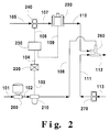
- Figure 2 is a schematic diagram of one embodiment of the present invention showing an isocentric low turbulence injector used in preparing a mixture of a coating composition containing dissolved solids and a non-solvent fluid.
- Figure 3 is a longitudinal cross-section of the isocentric low turbulence injector shown symbolically in Figure 2.
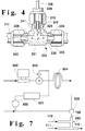
- Figure 4 is a detailed longitudinal cross-sectional view of a portion of the injector shown in Figure 3.
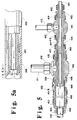
- Figure 5 is a longitudinal cross-section of a preferred embodiment of the isocentric low turbulence injector of the present invention.
- Figure 5a is an enlarged cross-section view of a portion of the injector shown in Figure 5.
- Figure 6 is an isometric diagram of a more preferred embodiment of the apparatus shown in Figure 3 in its utilization in a spray coating apparatus.
- Figure 7 is a schematic diagram of another embodiment of the apparatus which illustrates an automatic solvent flush system for the lower viscosity non-solvent injector port of the isocentric low turbulence injector shown symbolically in Figure 2.
- Figure 8 is a schematic diagram illustrating the inclusion in a portion of a spray coating apparatus of the most preferred embodiment of the iso-centric low turbulence injector shown in Figure 5.
- coating formulation or “coating composition” are understood to mean a typical, conventional coating composition which does not have any supercritical fluid admixed therewith.
- admixed liquid mixture or “admixed coating formulation” are meant to include an intimate mixture of a coating formulation with at least one supercritical fluid.
- the present invention is in no way limited to this preferred embodiment.
- the present invention encompasses the mixing of any plurality of fluids, one or more of which contains a dissolved solid (compounds below their melting point and as such are solid; polymers, and resins are examples), and likewise, one or more of which contains a non-solvent for said solid(s), to form a desired mixture for any intended subsequent use.
- critical temperature is defined as the temperature above which a gas cannot be liquified by an increase in pressure.
- critical pressure is defined as that pressure which is just sufficient to cause the appearance of two phases at the critical temperature.
- Near-supercritical liquids also demonstrate miscibility characteristics and other pertinent properties similar to those of supercritical fluids.
- the solute may be a liquid at the supercritical temperatures, even though it is a solid at lower temperatures.
- fluid "modifiers” can often alter supercritical fluid properties significantly, even in relatively low concentrations, greatly increasing miscibility for some solutes. These variations are considered to be within the concept of a supercritical fluid. Therefore, as used herein, the phrase "supercritical fluid” denotes a compound above, at, or slightly below the critical temperature and pressure, i.e., the critical point, of that compound.
- supercritical carbon dioxide fluid is preferably used with the coating compositions.
- nitrous oxide (N20) is a desirable supercritical fluid for admixture with the coating compositions.
- any of the aforementioned supercritical fluids and mixtures thereof are to be considered as being applicable for use with the coating formulations.
- the miscibility of supercritical carbon dioxide is substantially similar to that of a lower aliphatic hydrocarbon and, as a result, one can consider supercritical carbon dioxide as a replacement for the hydrocarbon solvent of a conventional coating formulation.
- there is a safety benefit also, because carbon dioxide is non-flammable.
- a single phase liquid mixture is able to be formed which is not only capable of being sprayed by airless spray techniques, but which forms a desired feathered spray pattern.
- the present invention is not narrowly critical to the type of coating compositions that can be sprayed provided that there is less than about 30% by weight of water in the solvent fraction of the formulation.
- any coating formulation meeting the aforementioned water limit requirement which is conventionally sprayed with an airless spray technique may also be sprayed by means of the methods and apparatus of the present invention.
- such coating formulations typically include a solids fraction containing at least one component which is capable of forming a coating on a substrate, whether such component is an adhesive, a paint, lacquer, varnish, chemical agent, lubricant, protective oil, non-aqueous detergent, or the like.
- at least one component is a polymer component which is well known to those skilled in the coatings art.
- the materials used in the solids fraction of the present invention such as the polymers, must be able to withstand the temperatures and/or pressures which are involved when they are ultimately admixed with the at least one supercritical fluid.
- Such applicable polymers include thermoplastic or thermosetting materials or may be cross linkable film forming systems.
- the polymeric components include vinyl, acrylic, styrenic, and interpolymers of the base vinyl, acrylic, and styrenic monomers; polyesters, oil-free alkyds, alkyds, and the like; polyurethanes, oil-modified polyurethanes and thermoplastic urethanes systems; epoxy systems; phenolic systems; cellulosic esters such as acetate butyrate, acetate propionate, and nitrocellulose; amino resins such as urea formaldehyde, melamine formaldehyde, and other aminoplast polymers and resins materials; natural gums and resins; rubber-based adhesives including nitrile rubbers which are copolymers of unsaturated nitriles with dienes, styrene-butadiene rubbers, thermoplastic rubbers, neoprene or polychloroprene rubbers, and the like.
- pigments pigment extenders, metallic flakes, fillers, drying agents, anti-foaming agents, and anti-skinning agents, wetting agents, ultraviolet absorbers, cross-linking agents, and mixtures thereof, may all be utilized in the coating formulation to be sprayed by methods of the present invention.
- pigments it is particularly desirable for pigments to be present in the coating formulation inasmuch as it has been found to aid in the diffusion of the supercritical fluid from the sprayed composition resulting in improved atomization.
- a solvent fraction is also typically employed in the coating formulations whether they be an adhesive composition or a paint, lacquer, varnish, or the like, in order to act as a vehicle in which the solid fraction is transported from one medium to another.
- the solvent fraction is comprised of essentially any active organic solvent and/or non-aqueous diluent which is at least partially miscible with the solids fraction so as to form either a solution, dispersion, or suspension.
- an "active solvent” is a solvent in which the solids fraction is at least partially soluble.
- a coupling-solvent is a solvent in which the polymeric compounds used in the solids fraction is at least partially soluble. Most importantly, however, such a coupling solvent is also at least partially miscible with water. Thus, the coupling solvent enables the miscibility of the solids fraction, the solvent fraction and the water to the extent that a single phase is desirably maintained such that the composition may optimally be sprayed and a good coating formed.
- Coupling solvents are well known to those skilled in the art and any conventional coupling solvents which are able to meet the aforementioned characteristics, namely, those in which the polymeric components of the solid fraction is at least partially soluble and in which water is at least partially miscible are all suitable for being used in the present invention.
- Applicable coupling solvents which may be used include, but are not limited to, ethylene glycol ethers; propylene glycol ethers; chemical and physical combinations thereof; lactams; cyclic ureas; and the like.
- Specific coupling solvents include butoxy ethanol, propoxy ethanol, hexoxy ethanol, isopropoxy 2-propanol, butoxy 2-propanol, propoxy 2-propanol, tertiary butoxy 2-propanol, ethoxy ethanol, butoxy ethoxy ethanol, propoxy ethoxy ethanol, hexoxy ethoxy ethanol, methoxy ethanol, methoxy 2-propanol, and ethoxy ethanol.
- lactams such as n-methyl-2-pyrrolidone
- cyclic ureas such as dimethyl ethylene urea.
- a coupling solvent is not necessary, but may still be employed.
- Other solvents, particularly active solvents, which may be present in typical coating formulations and which may be utilized include ketones such as acetone, methyl ethyl ketone, methyl isobutyl ketone, mesityl oxide, methyl amyl ketone, cyclohexanone and other aliphatic ketones; esters such as methyl acetate, ethyl acetate, alkyl carboxylic esters; ethers, such as methyl t-butyl ether, dibutyl ether, methyl phenyl ether and other aliphatic or alkyl aromatic ethers; glycol ethers such as ethoxy ethanol, butoxy ethanol, ethoxy 2-propanol, propoxy ethanol, butoxy 2-propanol and other glycol ethers; glycol ether esters such as butoxy ethoxy acetate, eth
- solvents which can function both as coupling solvents as well as active solvents and the one solvent may be used to accomplish both purposes.
- solvents include, for example, butoxy ethanol, propoxy ethanol and propoxy 2-propanol.
- Glycol ethers are particularly preferred.
- Suitable additives that are conventionally present in coating formulations that are intended for spray application may also be present: such as, curing agents, plasticizers, surfactants, and the like.
- FIG. 1 shows a process for forming a sprayable coating composition not using the isocentric low turbulence device of the present invention
- carbon dioxide which is a non-solvent for the polymer contained in the coating composition
- the cryogenic carbon dioxide at approximately 300 psig is first fed to an air driven carbon dioxide primer pump (not shown) located at the carbon dioxide feed system 2 for initial pressurization.
- the feed line in between the carbon dioxide source 2 and the primer pump is preferably insulated and also kept refrigerated by bleeding carbon dioxide (approximately 0.5 lb/hr) through a coil wrapped around the feed line.
- Surge tank 9 is provided to help damp flow fluctuations in the feed line.
- This liquid pump is a single-acting pump that utilizes a three-way cycling spool that is designed for pumping liquified gases under pressure without requiring refrigeration to avoid cavitation.
- the pressurized carbon dioxide is then regulated down with a pressure regulator 15 to a steady outlet pressure of about 1300 to about 2000 psig for a typical airless spray gun application.
- carbon dioxide flows through coriolis meter 21 for a true mass flow rate measurement.
- a capillary tube and a check valve connected in parallel at 20 is installed prior to the coriolis meter to help avoid a large flow surge and to smooth down the flow rate when pump 10 is activated.
- a globe valve and a capillary tubing connected in series at 25 is used to control and restrict the carbon dioxide flow during the initial start-up. After the system is pressurized, another globe valve 26 is opened to allow steady flow for normal operation. The measured flow of carbon dioxide enters the circulation loop at the mixing tee 39.
- a pressure relief valve 12 is used to protect the carbon dioxide system from overpressurization.
- the coating composition is fed from a coating supply system generally shown as 3 in the drawing.
- An accumulator 14 using nitrogen is utilized to offset any pressure pulsation.
- the coating flow rate is metered by a precision gear pump 18. Viscous coating from 3 is normally pressurized with a booster pump (not shown) to provide sufficient flow through filters and feed lines to the metering pump to avoid cavitation.
- the pump 18 supplies the positive pressure needed for feeding the coating composition to the recirculation loop.
- a precision gear measuring device 24 is used for measuring the flow rate of the coating composition.
- the speed command of the pump 18 is electronically controlled by the speed control system 17 that receives the input signal from the Micro Motion remote electronics unit 16.
- the coating metering rate is electronically adjusted by a coating flow feedback signal received from measuring device 24. The desired carbon dioxide mass ratio is therefore maintained when the two feeds are combined.
- the coating composition flows through one or more heaters 31 which are connected in series and a paint filter 32 before it enters the circulation loop at mixing tee 28.
- Pressure relief valve 29 is used to protect the coating composition system from overpressurization.
- a multi-channel flow computer 22 is used for both instantaneous and cumulative flow rate computation/indication.
- a general purpose data logger 27 with mathematical capability provides data printing and calculation functions of the characteristics of the two streams.
- the coating composition is combined with the circulation loop material at 90 o mixing tee 28, wherein the loop material flows in the run of the tee, and the coating composition enters through the branch of the tee.
- the admixture is passed through static mixer 40.
- the carbon dioxide is combined with the admixture of the circulation loop material and the coating composition at 90 o mixing tee 39, with the carbon dioxide entering through the branch of the tee. It is at this point in the spray coating apparatus wherein polymer(s) and resin(s) in the coating composition, which are dissolved in the solvent(s) come into intimate contact with the supercritical carbon dioxide, which may be, and generally is, a non-solvent for some or all of the contained polymer(s) and resin(s).
- the admixed coating formulation is passed through another static mixer 41 wherein the combined mixture is further mixed.
- the check valve 36 and 37 prevent back flow of the two fluids.
- the mixture is heated and controlled to the desired temperature of between about 40 o and about 70 o C in the circulation loop through two respective sets of high pressure heaters 45 and 65, both connected in series. Once heated to this temperature range, the carbon dioxide enters the supercritical state and remains in that state as it is being circulated until it is ultimately sprayed.
- the mixture also flows through two filters 47 and 66 and is circulated in the loop by a gear pump 61.
- An accumulator 43 is used to increase the loop capacity and also used to minimize the pressure pulsation in the loop when spray system 67 is activated.
- Pressure relief valves 53 and 63 are used to protect the loop from overpressurization.
- a sight glass 50 is used to view the mixture in the loop and observe its phase.
- a mass flow meter 54 is used to monitor the fluid density and flow rate in the circulation loop. The admixed liquid mixture is sprayed onto the substrates from spray system 67.
- the non-solvent carbon dioxide enters the 90 o mixing tee 39 through the branch of the tee in the state of being in turbulent flow and as such produces eddies along with the bubble, slug, etc., pattern believed common to such liquid-liquid flow regimes.
- the carbon dioxide merges with the flowing admixture of recycle loop admixed coating formulation and the coating composition that enters at the 90 o mixing tee 28 with said admixture flowing is in the laminar regime. It is believed, as previously delineated, that the aforementioned flow patterns produced by the mixing arrangement of tee 39 created the condition lead to the observed plugging with materials such as the nitrocellulose polymer.
- the isocentric low turbulence injector 260 of the present invention is shown symbolically and schematically in Figure 2 as it is typically located in the relevant portion of a spray coating apparatus.
- a compressible fluid which is a non-solvent for the dissolved solid, such as a polymer, contained in the coating composition, which is to be proportionately mixed with a non-compressible fluid containing said dissolved solid to form a desired admixture, is introduced from a supply source (not shown) to pumping means 200 via line 101.
- the compressible fluid is then pumped via line 102 past meter 210 for measuring the mass flow rate of the compressible fluid.
- pumping means 200 is not narrowly critical to the present invention. It may comprise any kind of a pump that is capable of pumping a compressible fluid and it may be driven by any conventional means.
- a conventional reciprocating pump which is well known to those skilled in the art is quite suitable.
- Mass flow rate measuring means 210 may comprise any conventionally available mass flow rate measuring device such as a Micro Motion Model D mass flow meter manufactured by Micro Motion Inc. of Boulder, Colorado. Generally, such mass flow rate measuring devices are known as coriolis meters. In contrast to most flow metering techniques which measure fluid volume, the measuring means 210 measures mass flow. Relying on volume as a meaningful measuring device is inaccurate at best when dealing with compressible fluids. The volume of a compressible fluid may change, sometimes radically, in response to changing fluid temperature, pressure or composition. One property of a fluid which is unaffected by environmental conditions is its mass. It is this characteristic of the compressible fluid which is desirably measured and from which the rate of flow of the non-compressible fluid is controlled.
- the mass flow rate measured by measuring means 210 is electronically transmitted by an electronic signal to a receiving device 220 via dotted line 103 which in turn sends out an electronic signal through dotted line 106 to electronic ratio controller 230. All of these electronic sensors and receivers are well known to those skilled in the art and are not narrowly critical to the present invention.
- non-compressible fluid is supplied via line 105 to pumping means 240.
- pumping means 240 is desirably a positive displacement pump and even more preferably a precision gear pump which are known to those skilled in the art.
- Such pumps are capable of delivering substantially precise amounts of the non-compressible fluid on demand.
- the ratio controller 230 contains logic circuitry which can be programmed to accept the electronic signal from device 220 and in turn generates a signal through dotted line 106 which controls the speed at which pump 240 operates.
- the amount of non-compressible fluid that leaves pump 240 and enters line 107 is precisely controlled to a predetermined ratio relative to the amount of compressible fluid measured and passed into line 108.
- the non-compressible fluid leaving pumping means 240 through line 107 is then passed into measuring device 250 to measure the actual flow rate of the non-compressible fluid.
- the flow rate that is measured may be on a volumetric or mass flow rate basis.
- a measuring device may comprise, for example, a precision gear meter such as is available from AW Company (Racine, WI.).
- the type of measuring device is not narrowly critical to the present invention. Since the material that is being measured is substantially non-compressible, its density will not materially vary over time. Accordingly, although what is being measured by this measuring device may be a volumetric flow rate, its accuracy here is quite acceptable in order to obtain an accurately proportioned final mixture.
- the flow rate measured by measuring device 250 generates a flow feedback signal which is electronically received by the ratio controller 230 through dotted line 109.
- the controller compares the actual flow rate that is measured by measuring device 250 with the required flow rate needed to provide the desired ratio of non-compressible and compressible fluids based on its preset programming and makes any adjustments needed to the speed of pump 240 so as to obtain that required flow rate.
- the non-compressible fluid leaving through line 110 and the compressible fluid leaving through line 108 enter isocentric injector merging means 260 via their respective lines in accordance with the present invention.
- check valves may be provided in each of lines 108 and 110 so as to prevent any backmixing.
- Recycle fluid in the circulation loop (not shown, but which loop may be comprised of static mixers, heaters, an accumulator, a sight glass, a density measuring device and the spraying means) comprised of the admixture of compressible and non-compressible fluids may be supplied via line 113 to recycle pumping means 270.
- pumping means 270 is a positive displacement pump and even more preferably a precision gear pump, which are known to those skilled in the art.
- the recycle fluid leaving pump 270 through line 111 may, in a preferred embodiment, be introduced into the merging means 260.
- the present invention in its broadest embodiment, does not require that recyled fluid be incorporated with the columnar fluid once it has been formed by the isocentric device to form, in turn, yet a second columnar fluids structure comprised of an innermost core of non-solvent fluid, an adjacent annulus of a fluid containing dissolved solids, and an outermost annular layer containing the recyle fluid.
- the broadest embodiment of the present invention comprises the formation of the inner core of non-solvent surrounded by the outer adjacent annulus of the fluid containing the dissolved solids.
- Injector merging means 260 may comprise any effective mixing device capable of merging the two fluids without film formation on the walls due to the precipitation of dissolved solids contained within one of the fluids, causing plugging therein, and/or causing plugging of downstream apparatus connected via line 112.
- the compressible fluid (a non-solvent for the polymer dissolved in the coating composition) enters vertically downwards, via line 108, through a small diameter tube that traverses vertically downwards internally in the merging means to just before it merges with the horizontally flowing recycle fluid, entering via line 111, that is flowing internally in the run of the merging means.
- Non-compressible fluid (containing the dissolved solids) enters the injector merging means 260, via line 110, horizontally into an annulus formed between the outside wall of the vertical tube and the inside wall of that part of the merging means in the vertical direction. (See Figure 3.) At the point of entering the annulus, the non-compressible fluid experiences a 90 o change in its flow path.
- line 112 is connected to a static mixer to provide a well mixed flowing stream.
- the present invention is particularly applicable, although certainly not limited to, being able to prepare an admixed liquid mixture of an accurately proportioned amount of supercritical fluid, particularly supercritical carbon dioxide, with a coating composition.
- Figure 3 illustrates a cross-sectional view of one form of the isocentric low turbulence injector merging means 260 shown in Figure 2 (which is a segment of the spray coating apparatus) that can be used to effect the desired merging of the non-solvent compressible fluid, the incompressible coating composition fluid, and, if desired, the recycle admixed coating formulation fluid, without resulting in the undesirable solids formation and plugging of the apparatus therefrom.
- the scope of the present invention also includes other injector designs which are capable of accommodating the merging of the non-solvent compressible fluid and the coating composition alone and the merging of the non-solvent compressible fluid and the coating composition with recycled admixed coating formulation recycle without solids formation within the device which may cause plugging of the said merging devices and other contiguous devices.
- the merging means assembly 260 comprises two tube fitting tees 300 and 301 and tubing 108, all of which may be any commercially obtainable tubing fittings and tubing such as SWAGELOKTM tube fittings and tubing.
- the branch 329 of union tee 300 is connected to the run 330 of union tee 301 by tubing 309, one end of which is secured and retained to branch 329 of tee 300 by back and front ferrule combination 308 and threaded nut 307.
- the other end of tubing 309 is secured and retained to one end of the run 330 of union tee 301 by back and front ferrule combination 314 and threaded nut 310.
- Tubing 111 is connected to one end of the run 331 of the tee 300 and is secured and retained by front and back ferrule combination 313 and threaded nut 302.
- Tubing 112 is connected to the reducer 304 and is secured and retained by front and back ferrule combination 311 and threaded nut 333, with the reducer 304 attached to the other end of the run 331 of union tee 300 and is secured and retained by front and back ferrule combination 312 and threaded nut 303.
- the tubing 110 is connected to the reducer 319 and is secured and retained by front and back ferrule combination 321 and threaded nut 320, with the reducer 319 connected to the branch 332 of the tee 301 and is secured and retained by front and back ferrule combination 317 and threaded nut 318.
- the other end of the run 330 of the tee 301 is connected to the bored through reducer 325 which is secured and retained to 301 by the front and back ferrule combination 324 and threaded nut 323.
- Tubing 108 is passed through bored reducer 325 and its open end is positioned a distance H from the top of the bore of run 331 of tee 300. This position of the tubing 108 is secured and retained by front and back ferule combination 326 and threaded nut 327.
- Distance H is important in attaining the liquid-liquid fluid flow pattern resulting in the desired elimination of the plugging problem.
- this distance which is measured as relative diameters of tube 108, is in the range of from about 0 to about 2.0 diameters, more preferably it is in the range of from about 0.5 to about 1.5 diameters, and most preferably, distance H is about 1.0 diameter of tube 108.
- the outer wall of tubing 108 forms the inner wall of an annulus, the outer wall of which is formed by the bore of run 330 of tee 301.
- the outer diameter of tubing 108 and the inner bore of tee 301 are selected to form an annulus with a cross-sectional area such that, based on the physical properties of the non-compressible solids containing fluid, the flow velocity therein is about equal to the flow velocity of the compressible non-solvent fluid flowing internally within the tube 108, based upon its inside diameter and physical properties.
- tubing 111 and 309 which abut the milled shoulders of tee 300 are milled to form a shape 328 that is similar to the frustum of a cone, as shown on tubing 111.
- the larger diameter end of reducer 304, which also abuts the milled shoulder of tee 300 is likewise milled in the shape of the frustum of a cone.
- Such milling desirably provides a smooth transition at the juncture of the tubing and the reducer as they are positioned at the milled shoulders within the tee, thereby further minimizing the formation of eddies which would contribute to undesired turbulence.
- tubing 108 positioned by distance H from the upper surface of the bore of run 331 is milled internally to form a shape similar to the frustum of a cone, resulting in a knife-edge shape where the compressible fluid exits tubing 108.
- tubing 108 may alternately be milled on the outer diameter, or, indeed, may be milled both internally and externally to effect the desirable knife-edge shape.
- the formation of undesirable eddies is minimized along the merge line within tee 300, thereby creating laminar, or nearly laminar, streamlines in all of the fluid streams, which then have little, if any, velocity vectors normal to the axial flow of fluid within said tee.
- the non-solvent fluid is mainly prevented from undesirably contacting the walls of the merging means as it is interjected into the recirculating fluid stream from the recycle loop (line 111 in Figure 2), while some velocity and diffusion gradients establish some gentle mixing action within the main body of the combined streams.
- tubing 108 is juxtapositioned in tee 300 such that it is concentric with the inner wall of branch 329 of said tee.
- the cone end of tubing 108 is fabricated by milling the internal wall of said tubing in the general shape of a frustum of a cone with an included angle J, which is preferably an angle of about 15 to about 60 degrees, more preferably at an angle of from about 15 to about 30 degrees.
- Such an angle desirably produces a knife edge configuration such that eddies are minimized along the merge area of the fluids flowing in tubing 108 and the annulus formed by the inner wall of tee 300 and the outer wall of tubing 108.
- end 335 of reducer 304 positioned to abut the shoulder of tee 300 is milled in the general shape of a frustum of a cone to effect a smooth transition at said juncture, thereby minimizing the formation of eddies in the fluid flowing in this vicinity as well.
- end 328 of tubing 111 and end 341 of tubing 309 are milled in the general shape of a frustum of a cone to create the same effect of a smooth transition as the fluids flow from one component or part to another within the apparatus; that is, generating a transition while maintaining a minimum of eddies.
- the isocentric low turbulence injector merging means 260 is continuously supplied with admixed coating formulation fluid flowing in laminar flow from the recycle loop in line 110 into run 331 of tee 300 wherein, at the intersection of the branch 329 of tee 300, it merges with the non-solvent carbon dioxide fluid centrally captured within the coating composition fluid entering tee 300, which may be flowing in the turbulent, the transition, or the laminar flow regime, but most preferably is in laminar flow.
- the merged fluid flow stream also in laminar flow, then proceeds through reducer 304 into line 112, which flow supplies the recirculation loop with admixed coating formulation to the portion of the apparatus upstream of the components of the spray coating apparatus, as shown in Figure 1, consisting of, but not limited to: the static mixers, an accumulator, the heaters and filters, the sight glass, the density meter and the spray gun, all of which are before the circulation loop pump (shown as pump 61 in Figure 1 and pump 270 in Figure 2).
- This loop operates to continuously supply proportioned, mixed, pressurized and heated admixed coating formulation to the spray gun (at a temperature and a pressure which are just below, at, or above the supercritical point of the carbon dioxide).
- the laminar flow streamlines and the annular flow pattern believed established by the coating composition and the recycle admixed coating formulation streams prevent carbon dioxide from contacting the walls of the fittings and the tubing which comprise the isocentric low turbulence injector, while some velocity gradients (eddies) normal to the flow establish some mild mixing action within the main body of the commingled streams.
- the concentration of the non-solvent carbon dioxide is below that of the saturation level for the dissolved polymer, thereby minimizing and/or preventing precipitation of said polymer or resin dissolved in the coating composition.
- the recycle admixed coating formulation liquid stream flow rate is several times that of the sum of the coating composition and carbon dioxide stream flows.
- isocentric low turbulence injector shown in Figures 3 and 4 illustrates tee 300 with a conventional 90 o angle existing between the merged coating composition and carbon dioxide flow stream relative to the recirculation stream
- other designs would also be suitable to attain the benefits of the present invention.
- a lateral with an angle less than 90 o or a "Y" , with a continuum of angles possible between the branches thereof are also suitable.
- Figure 5 illustrates a cross-sectional view of a more preferred embodiment of the isocentric low turbulence injector merging means that can be used to effect the desired merging of the non-solvent compressible fluid with the coating composition and then, the merging of that merged and commingling composition with the recycle admixed coating formulation fluid to provide a non-solvent fluid as a core within a surrounding annular layer of coating composition which, in turn, is surrounded with an outer annular layer of recyle admixed coating formulation which results in an improved apparatus for minimizing the precipitation of undesirable solids.
- this columnar fluid structure traverses along its path, the three fluids intermingle with one another to ultimately form an admixed coating formulation
- the merging means assembly 400 comprises two tube fitting union tees 401 and 402, two bored through tube fitting reducers 403 and 404, a tube fitting reducer 405, a tube fitting union 406, tubing 407, 408, 409, 410, 411, and 412, all of which may be any commercially available tubing fittings and tubing such as SWAGELOKTM tube fittings and tubing.
- the bored through reducer 403 is connected to the run of union tee 401 and is secured and retained by back and front ferrule combination and threaded nut 414.
- Tubing 407 passes through the other end of bored reducer 403 and is secured and retained by ferrules and threaded nut 413.
- the other end of the run of union tee 401 is connected to the run of union tee 402 through tubing 408, one end of tubing 408 is secured and retained to union 401 by ferrules and threaded nut 416.
- Tubing 412 is connected to the branch of union tee 401 and is secured and retained by ferrules and threaded nut 415.
- Tubing 408 is passed through bored through reducer 404, extending through the run of union tee 402, and is secured and retained by ferrules and threaded nut 417 to bored through reducer 404.
- Bored through reducer 404 is secured and retained to union tee 402 by ferrules and threaded nut 418.
- the diameter of tubing 407 is smaller than the diameter of tubing 408, and tubing 407 extends to within distance K of the end of tubing 408.
- Distance K is important in providing the laminar, or near laminar, fluid flow pattern which results in obtaining the objectives of the present invention.
- the preferable distance, measured in relative diameters of tube 407 is from about 0 to about 2.0 diameters, more preferably, it is from about 0.2 to about 1.0 diameter, and, most preferably, it is about 0.5 diameter.
- the other end of the run of union tee 402 is connected by tubing 409 to union 406, where this end of tubing 409 is secured and retained by ferrules and threaded nut 420.
- Tubing 411 is connected to the branch of union tee 402 and is secured and retained by ferrules and threaded nut 419.
- the end of tubing 409 connected to union 406 is secured and retained to the union by ferrules and threaded nut 421.
- the other end of union 406 is connected with reducer 405, which is secured and retained to 406 by ferrules and threaded nut 422.
- Tubing 410 is connected to reducer 405 and is secured and retained by ferrules and threaded nut 423.
- the other end of tubing 410 is connected to a static mixer (not shown).
- the diameter of tubing 409 is greater than the diameter of tubing 408.
- the merging means 400 has the outer wall of tubing 407 forming the inner wall of an annulus, the outer wall of which is the inner wall of tubing 408.
- the outer wall of tubing 408 forms the inner wall of an annulus, the outer wall of which is the inner wall of tubing 409.
- the outer and inner diameters of said tubing 407, 408 and 409 are selected such that the velocity of fluids flowing within tubing 407 and the aforementioned two annuli are all as equal as possible in order for the liquid flows to form streamlines when the flows regimes are in the desired laminar region which are not wavy and minimize mixing in the axial direction, and also to minimize the formation of bubbles or plugs, and the like.
- the lengths of tubes 407, 408, and 409 within the merging apparatus 400 are not altogether critical to operating the apparatus successfully, optimal results occur when sufficient calming sections are provided such as to ensure fully developed streamlines for dissipating any eddies that may have developed.
- the length of tubing 409 may be any practical length but typically is in the range of from about 7 to about 20 times its outer diameter and more preferably is from about 10 to about 15 times its outer diameter.
- the length of tube 408 is generally made approximately equal to the length of tube 409 and positioned such that the outlet end of tube 408 is situated at the approximate midpoint of the length of tube 409.
- the length of tube 407 in this emobodiment of the present invention is made to be approximately equal to twice the length of tube 409 and is positioned within tube 408 so as to provide the desired distance K discussed above.
- the ends of tubing and shoulders of fittings are coned to provide smooth fluid flow transitions, thereby minimizing the formation of eddies in the flowing liquids.
- the merging means 400 is continuously supplied recycled coating formulation fluid by pump 270 in laminar flow via tubing 411 which is connected to recycle loop line 111.
- Tubing 411 connects to the run of union tee 402 (see Figure 5) wherein said fluid flows in the annulus formed between tubing 408 and tubing 409 (see Figure 5a).
- Coating composition is supplied by pump 240 and flows through metering means 250 and line 110 which connects to tubing 412 at injector 400.
- the supercritical carbon dioxide fluid is supplied by pump 200 and flows via line 102 through mass measuring means 210 and through line 108 which connects to tubing 407 at the injector means 400, preferably but not necessarily in laminar flow, and exits tubing 408 as a central core of fluid, as indicated by the flow arrows as shown in Figure 5a.
- the outer annulus of admixed coating formulation protect the outer wall of the merging apparatus from forming a film of precipitated polymer.
- the fluid admixture flows from the larger diameter portion of reducer 406 (see Figure 5) into the smaller diameter portion, some eddies are formed near the outer wall of the reducer, said eddies do indeed aid the mixing process, which at this point, because the apparatus of the present invention has achieved the objective of minimizing solids formation, we are no longer concerned about plugging, but indeed desire homogenization of the flowing fluid stream, which is accomplished as the fluid flows from injector 400 through tubing 410, which is connected to line 112 from which the fluid admixture flows into static mixer 430 for vigorous mixing (see Figure 8).
- Eddies are also formed when the coating composition supplied in tubing 412 changes direction in tee 401 and when the recycle admixed coating formulation supplied in tubing 411 changes direction in tee 402.
- such eddies are allowed to dissipate with the reestablishment of the laminar flow streamlines as these materials flow axially along said lengths, thereby preserving the desirable minimization of precipitation of solids due to the contacting of bubbles, plugs, etc., of the non-solvent carbon dioxide with polymer dissolved in the coating composition fluid.
- Figure 6 in which the same reference numerals are used to identify like elements as shown in Figures 2 and 3, illustrates, in an isometric view, an embodiment of the present invention wherein pipe size reduction, followed by out-of-plane ells placed beyond the isocentric low turbulence injector promotes cross-mixing of the laminar flow streamlines, thereby furthering diffusion and flow of the carbon dioxide normal to the flow axis, with the completing of the homogenization of the admixture in a static mixer, which provides the necessary vigorous mixing action.
- the components of the method and apparatus included in Figure 6 may be commercially available valves, tubing fittings and tubing, such as SWAGELOKTM tube fittings and tubing. Preferably, all components are made of stainless steel.
- carbon dioxide is continuously supplied from a source (not shown) through line 523, which may be 1/8 inch diameter stainless steel tubing, and fed into tubing reducer 510, which may be a 3/8 x 1/4 inch reducer, and then flows into 3/8 inch check valve 525 which is connected to another 3/8 x 1/4 inch tubing reducer 512, and exits said reducer which is connected to 1/4 inch diameter tubing 108, which forms an integral part of the isocentric injector 260, wherein said tubing enters 260 through reducer 325, which may be a 1/2 x 1/4 inch reducer that is connected to 1/2 inch tee 301, which is a part of injector 260, wherein the carbon dioxide is injected into coating composition also flowing into injector 260 tee 301.
- a source not shown
- line 523 which may be 1/8 inch diameter stainless steel tubing
- tubing reducer 510 which may be a 3/8 x 1/4 inch reducer
- 3/8 inch check valve 525 which is connected to another 3/8 x
- the coating composition is supplied from a source (not shown) through line 110, which may be 3/8 inch diameter stainless steel tubing, and flows into check valve 511 which is connected to tubing reducer 319, which may be a 1/2 x 3/8 inch reducer, and then flows into tubing union tee 301.
- Coating composition is supplied from the recycle loop source (not shown) through line 513, which may be 3/8 inch diameter tubing, and flows into 3/8 inch check valve 514, where upon exiting the check valve the fluid flows into 1/2 x 3/8 inch reducer 515, and then through 1/2 inch diameter by about 6 inches long tubing 111 into tubing tee 300, which is an integral part of injector 260.
- the 6-inch length of tubing 111 provides a calming segment following the reducer 515 that is present to afford reduction in the impact on the flowing fluid of any eddies that may be formed as the said material flows through the reducer and, thereby, allows the redevelopment of the desirable laminar flow streamlines in the flowing fluid. As previously described, it is within tee 300 where the merging of these three aforementioned fluid streams occurs.
- the series of out-of-plane tubing ells 516, 518, and 520, and the tubing size reduction in tubing 112, 517, and 519 provide desirable moderate axial mixing which aids in the distribution of the carbon dioxide to form the homogeneous, single-phase admixed coating formulation without the undesirable precipitation of dissolved polymer.
- this embodiment of the present invention presents specific sizes for the apparatus, it is apparent that any combination of sizes of apparatus may be utilized provided said combination provides the objectives of the present invention.
- an automatic solvent flushing method and apparatus may be utilized to flush the carbon dioxide injector tubing with a minimal amount of flush solvent to prevent precipitation induced blockage of the carbon dioxide injection port by dissolving any unexpected incipient solids build-up with an automatically controlled intermittent solvent flush.
- One such method and apparatus is shown symbolically and schematically in Figure 7.
- flush solvent fluid which may be any compound which is a solvent for the polymer(s) or resin(s) contained in the coating composition fluid, but is preferably selected from one or more of those solvents present in the coating composition, is supplied from a convenient source (not shown) to pump 602 which is connected to control valve 603 which is activated by an electric signal from flow switch 600 and time delay relay module 601. Valve 603 is connected to flow restrictor 604, which is then connected to the tee 605. Tee 605 is also supplied carbon dioxide fluid, which is supplied front a convenient source (not shown) to the spray coating apparatus (not shown) where it mixes with the flush solvent fluid and then the admixture flows through line 108 into the isocentric low turbulence injector 260.
- the merged fluids exit injector 260 through line 112 and flow, thereby, into what constitutes the circulation loop upstream of mixers, heaters, the spray gun, and the like (not shown), of the spray coating apparatus.
- Pumping means 602 may comprise any kind of pump that is capable of pumping the flush solvent at the required pressure and it may be driven by any conventional means.
- a reciprocating pump, or a gear pump which are well known to those skilled in the art are quite suitable.
- flow switch 600 may comprise any conventional means which can detect flow and generate an electronic signal, which may be such a device already existing within the spray coating apparatus which is detecting and measuring flow. The flow detected by device 600 generates a signal which is electronically received by a conventional control device (not shown) and when there is no flow sends an electronic signal, which is received by the valve 603, causing the valve to be positioned in its fully open position.
- Valve 603 may comprise any conventional on/off valve.
- the rate of flow of the flush solvent is controlled by the differential pressure developed by flow restrictor 604, which may comprise any conventional device, such as, for example, a piece of capillary tubing of prescribed length, which is formed into a coil to conserve space, that provides a drop in the pressure of the flowing flush solvent such that the predetermined prescribed solvent flow rate is achieved.
- the flow of the flush solvent fluid is stopped when valve 603 is activated to achieve the fully closed position when receiving an electronic signal generated from time delay relay module 601, which activates after a preselected interval of time.
- Time delay module 601 may comprise any conventional device that accomplishes this purpose.
- the time delay relay module is preset for the selected interval that is long enough to permit adequate flushing to clean the injector, but not so great as to adversely dilute the admixed coating formulation fluid which could affect the quality of the sprayed coating.
- flush solvent may flow into the injector tube at a nominal rate of about 1.0 cm3/min. The rate selected, or course, is determined by the geometry of the selected flow restrictor 604, the differential pressure drop across said restrictor, the physical properties of the fluid, and the design size of the spray coating apparatus.
- time delay relay module 601 After the preset time interval selected in module 601 passes, time delay relay module 601 generates an electric signal which activates on/off valve 603 causing it to become fully closed, which such action also causes pump 602 to cease pumping. Then, continuation of the carbon dioxide flow, either prior to or following the delay time period, will be detected by the flow switch/flow sensor 600, and the system will reset and return to the ready state wherein carbon dioxide is flowing under normal control of the spray coating apparatus.
- Example 2 illustrates the practice of the present method and apparatus with the injector assembled according to the longitudinal cross-section diagram shown in Figure 3 and placed in the spray coating apparatus illustrated in Figure 2 shown symbolically as item 260.
- the injector device is comprised of the items included in Table 2, which are shown in Figure 3.
- TABLE 2 Item No. Description 108 SS tubing 1/4" O.D. x 0.035" wall thickness, with length greater than 8 inches. 110, 111, 112 SS tubing 3/8" O.D. x 0.035" wall thickness, of optional length. 300, 301 SS SWAGELOKTM 1/2" Union Tee. 302, 303, 307, 310, 318, 323, SS SWAGELOKTM 1/2" Nut.
- tubing 108 was positioned at a distance H of about 0.25 inch, as shown in Figures 3 and 4.
- Tubing 108 fed the compressible carbon dioxide to injector 260, with the carbon dioxide, which was being supplied to the apparatus from a cylinder (not shown) at room temperature and at about 800 psig, and then pressured to about 2000 psig by pump 200, a Haskel Model DSF-35 single acting air driven plunger pump, with its set flow rate of about 36 grams per minute being measured by mass flowmeter 210, a Micro Motion Mass Flowmeter, Model DS-006-S-100 to give a true mass flow rate measurement.
- Coating composition was fed to injector 260 through tubing 110.
- Ratio controller 230 contains logic circuitry which was programmed to generate a signal to control the speed of pump 240.
- the amount of coating composition was controlled to the predetermined ratio of coating composition to carbon dioxide of about 2.44:1 to give 29% by weight of carbon dioxide in the admixed liquid mixture.
- the coating composition was then fed through measuring device 250, an AW, Model ZHM-02 precision gear meter to measure its actual flow rate.
- the coating composition was then heated to about 50 o C in a heater (not shown located in line 110), an electric high-pressure paint heater. As these two fluid streams flowed together just above the entrance of the branch of tee 300 into its run, the coating composition formed an annular flow pattern surrounding a flowing center core of supercritical carbon dioxide.
- This combined flow of fluid then flowed into the run of the tee 300 where it joined the recycle steam of admixed coating formulation fluid being supplied through line 111.
- This stream cycles through a recirculation loop (not shown) starting where the combined fluids stream exits injector 260 through line 112, with the energy for supplying the circulation provided by pump 270, a Zenith, Model HLB-5592 gear pump, the inlet to which was line 113, which controlled the pressure within the recirculation loop at about 1600 psig.
- the admixed coating formulation leaving injector 260 and flowing into the recirculation loop was processed in devices (not shown) which mixed the fluid in Kenics static mixers, then heated it to about 60 o C in a Binks high-pressure paint heater, fed it through a sight glass to provide for visual observation of the flowing fluid, then measured its density in a Micro Motion Density meter, and finally feeding it to the airless spray gun, Nordson, Model A7A with circulation, from which the preproportioned, pressurized, heated admixed coating formulation was sprayed onto the substrate.
- the portion of material not exiting the system through the spray gun flowed through line 113 to pump 270, thus completing the recirculation loop.
- the loop flow rate was about three times the rate of the combined flow rates of the carbon dioxide and the coating composition.
- the spray gun was operated for about 5 minutes, with the apparatus observed to be maintaining good control of the coating composition pump and the carbon dioxide flow rate, with the pressure in the recirculation loop being maintained at a constant level of about 1600 psig, unlike the aforementioned observations with the mixing tee used in the apparatus of the prior art, where the pressure in the circulation loop oscillated as did the carbon dioxide feed rate and pressure. Observation of the sight glass showed only small, discrete particles present, there were no large agglomerates, which indicated that no harmful deposits of precipitated polymer were occurring.
- the non-compressible coating composition containing a nitrocellulose polymer was prepared by mixing the following materials: 3648 grams of Hercules Nitrocellulose wet with 2-propanol, which contains 70% non-volatile nitrocellulose; 5680 grams of Reichhold BECKOSOL Synthetic Resin Solution CO9195-02, a non-oxidizing short coconut oil alkyd dissolved in methyl amyl ketone, which contains 75% non-volatile alkyd polymer; 688 grams of dioctylphthalate plasticizer; 4784 grams of methyl amyl ketone solvent; 1200 grams of normal butanol solvent.
- the coating composition contained about 42.6%, by weight of nonvolatile polymer solids. It had a viscosity of about 1510 centipoise, and a specific gravity of about 0.9784.
- Example 2 The same apparatus, coating composition, and spray mixture were used as in Example 1.
- the feed rates of both the carbon dioxide and the coating composition were varied over a range of about 50 to 250 grams per minute for the carbon dioxide and of about 122 to 612 grams per minute for the coating composition, with the carbon dioxide content of the admixture of these two flows being held constant at about 29% by weight.
- Reynolds numbers were calculated, and these and the related flow regimes are likewise shown in this table. The flow regime is defined to be laminar when the Reynolds number is less than or equal to 2000, turbulent when the number is 3000 or greater, and in the transition region for values between 2000 and 3000.
- Example 4 The same apparatus, procedure, coating composition, and spray mixture was used as in Example 2, except that the size of the iso-centric low turbulence injector 260, as shown in Figure 3, was modified to increase the size of the carbon dioxide injector tube to 1/2 inch, with the rest of the components sized-up appropriately, to provide laminar flow of the carbon dioxide at the lower flow rates.
- Table 4 TABLE 4 CO2 Feed Rate, gm/min 50 100 200 250 Reynolds Number 970 1940 3880 4850 CO2 Flow Regime Lam Lam Turb Turb
- the carbon dioxide feed rate at which the transient flow regime occurred was at about 105 grams per minute, and became turbulent at about 155 grams per minute.
- Example illustrates the practice of the preferred embodiment of the present method and apparatus with the apparatus assembled according to the longitudinal cross-section diagram shown in Figure 5, and placed within the spray coating apparatus, as illustrated in Figure 8, and using the same procedure, coating composition, and spray mixture as was used in Example 2.
- Injector 400 is comprised of the items included in Table 5.
- Table 5 TABLE 5 Item No. Description 401 SS SWAGELOKTM 3/4" Union Tee. 402 SS SWAGELOKTM 1" Union Tee. 403 SS SWAGELOKTM 1/2" x 3/4" Bored Reducer. 404 SS SWAGELOKTM 3/4" x 1" Bored Reducer. 405 SS SWAGELOKTM 1/2" x 1" Reducer. 406 SS SWAGELOKTM Union. 407, 410 SS tubing 1/2" O.D. x 0.049" wall thickness, 17-1/8" long. 408, 412 SS tubing 3/4" O.D. x 0.065" wall thickness, 13" long.
- injector 400 as shown in the figure, was installed in a vertical configuration.
- the carbon dioxide feed line 108 was connected to tubing 407 as it entered injector 400
- the coating composition feed line 110 was connected to tubing 412 as it entered the injector
- the recycle line 111 was connected to tubing 411 as it entered injector 400.
- the carbon dioxide feed was supplied from a cylinder (not shown), flowed at a rate of about 267 grams per minute through line 101, was pressured up to about 2000 psig by pump 200, flowed through line 102 and then through mass metering means 210, through line 108 to tubing 407, through which it was injected into injector 400 in the transition regime (a condition between laminar and turbulent regimes) with a Reynolds number of about 2770.
- the coating composition was supplied from a feed tank (not shown) by line 105 and flowed at a feed rate of about 590 grams per minute into pump 240 wherein it was pressured up to about 1500 psig, flowed through metering means 250, then flowed through line 110 to tubing 412, through which it was introduced into injector 400 in the laminar flow regime with a Reynolds number of about 2.
- the recycle admixed coating formulation was supplied by line 113 to pump 270 which maintained the flow rate in the circulation loop (not completely shown) at about 2500 grams per minute while maintaining the pressure at about 1490 psig, with the pump effluent flowing through line 111 to tubing 411 wherein it was introduced into injector 400 while flowing in the laminar regime with a Reynolds number of about 120.
- the temperature of the material in the circulation loop was maintained at about 60 o C by heating means (not shown) contained within the said loop.
- Other devices, not shown, provided operating control of the spray coating apparatus, including the proportioning of the carbon dioxide feed and the coating composition feed to the prescribed ratio, which was about 2.21:1 coating composition to carbon dioxide.
- the admixed coating formulation had a carbon dioxide content of about 31% by weight.
- the coating formulation and carbon dioxide mixture exiting injector 400 through tubing 410 flowed through line 112 into static mixer 430 where vigorous mixing action produced a homogeneous admixture which then flowed through the heating and other means and was sprayed onto the substrate by the spray gun (none of these devices are shown in Figure 8).
Landscapes
- Engineering & Computer Science (AREA)
- Mechanical Engineering (AREA)
- Chemical & Material Sciences (AREA)
- Chemical Kinetics & Catalysis (AREA)
Applications Claiming Priority (2)
| Application Number | Priority Date | Filing Date | Title |
|---|---|---|---|
| US676512 | 1991-03-28 | ||
| US07/676,512 US5105843A (en) | 1991-03-28 | 1991-03-28 | Isocentric low turbulence injector |
Publications (2)
| Publication Number | Publication Date |
|---|---|
| EP0505624A2 true EP0505624A2 (de) | 1992-09-30 |
| EP0505624A3 EP0505624A3 (en) | 1993-03-17 |
Family
ID=24714832
Family Applications (1)
| Application Number | Title | Priority Date | Filing Date |
|---|---|---|---|
| EP19910122004 Withdrawn EP0505624A3 (en) | 1991-03-28 | 1991-12-20 | Isocentric low turbulence injector |
Country Status (3)
| Country | Link |
|---|---|
| US (1) | US5105843A (de) |
| EP (1) | EP0505624A3 (de) |
| CA (1) | CA2058189A1 (de) |
Cited By (1)
| Publication number | Priority date | Publication date | Assignee | Title |
|---|---|---|---|---|
| CN106556506A (zh) * | 2016-11-29 | 2017-04-05 | 中国石油大学(华东) | 测量超临界二氧化碳压裂裂缝中流型分布的装置 |
Families Citing this family (42)
| Publication number | Priority date | Publication date | Assignee | Title |
|---|---|---|---|---|
| US5254260A (en) * | 1992-05-12 | 1993-10-19 | Union Carbide Chemicals & Plastics Technology Corporation | Membrane injector |
| US5443796A (en) * | 1992-10-19 | 1995-08-22 | Nordson Corporation | Method and apparatus for preventing the formation of a solid precipitate in a coating material formulation |
| MX9504934A (es) * | 1994-12-12 | 1997-01-31 | Morton Int Inc | Revestimientos en polvo de pelicula delgada lisa. |
| AU6488596A (en) * | 1995-07-11 | 1997-02-10 | Ag-Chem Equipment Company, Incorporated | Comprehensive product delivery system |
| DE19536856C2 (de) * | 1995-10-03 | 1997-08-21 | Danfoss As | Mikromischer und Mischverfahren |
| US6075074A (en) * | 1996-07-19 | 2000-06-13 | Morton International, Inc. | Continuous processing of powder coating compositions |
| US6114414A (en) * | 1996-07-19 | 2000-09-05 | Morton International, Inc. | Continuous processing of powder coating compositions |
| US5766522A (en) * | 1996-07-19 | 1998-06-16 | Morton International, Inc. | Continuous processing of powder coating compositions |
| US6583187B1 (en) | 1996-07-19 | 2003-06-24 | Andrew T. Daly | Continuous processing of powder coating compositions |
| DE19824802A1 (de) * | 1998-06-03 | 1999-12-09 | Itw Gema Ag | Pulverförder-Injektor |
| US6048369A (en) * | 1998-06-03 | 2000-04-11 | North Carolina State University | Method of dyeing hydrophobic textile fibers with colorant materials in supercritical fluid carbon dioxide |
| US6261326B1 (en) | 2000-01-13 | 2001-07-17 | North Carolina State University | Method for introducing dyes and other chemicals into a textile treatment system |
| US7438326B1 (en) * | 2000-08-31 | 2008-10-21 | Tuf-Tite, Inc. | Tee baffle for use at inlet or outlet of septic and other on-site waste disposal systems |
| US6676710B2 (en) | 2000-10-18 | 2004-01-13 | North Carolina State University | Process for treating textile substrates |
| US20020146509A1 (en) * | 2001-02-06 | 2002-10-10 | Kodokian George K. | Micronization process and polymer particles produced therefrom |
| US20070025181A1 (en) * | 2003-06-03 | 2007-02-01 | Mixpac Systems Ag | Device for connecting a tubule to a mixer |
| FR2876832B1 (fr) * | 2004-10-15 | 2007-02-02 | Framatome Anp Sas | Element de tuyauterie en forme de t d'un circuit auxiliaire d'un reacteur nucleaire, piece de raccordement et procede de realisation et de montage de l'element de tuyauterie |
| US8322430B2 (en) * | 2005-06-03 | 2012-12-04 | Shell Oil Company | Pipes, systems, and methods for transporting fluids |
| US20070000828A1 (en) * | 2005-07-01 | 2007-01-04 | Norman Wesley M | Fluid coupling |
| US7513307B2 (en) * | 2006-02-13 | 2009-04-07 | Team Co2 Holdings Llc | Pumping system for injecting a mixture of liquids via a well into a subterranean formation |
| US7694731B2 (en) * | 2006-02-13 | 2010-04-13 | Team Co2, Inc. | Truck-mounted pumping system for treating a subterranean formation via a well with a mixture of liquids |
| WO2008035194A2 (en) * | 2006-09-21 | 2008-03-27 | Vetco Gray Scandinavia As | A method and an apparatus for cold start of a subsea production system |
| US20080098900A1 (en) * | 2006-11-01 | 2008-05-01 | Babatunde Aremu | Beverage manufacture using a static mixer |
| SA111320501B1 (ar) * | 2010-06-04 | 2014-08-11 | Dow Global Technologies Llc | إذابة مواد خافضة للتوتر السطحي في ثاني أكسيد كربون فوق حرج لاستعادة زيت محسن |
| TWI551803B (zh) | 2010-06-15 | 2016-10-01 | 拜歐菲樂Ip有限責任公司 | 低溫熱力閥裝置、含有該低溫熱力閥裝置之系統及使用該低溫熱力閥裝置之方法 |
| US9528607B2 (en) * | 2011-12-01 | 2016-12-27 | Garlock Sealing Technologies, Llc | Stuffing box flow diverter and methods therefor |
| TWI525184B (zh) | 2011-12-16 | 2016-03-11 | 拜歐菲樂Ip有限責任公司 | 低溫注射組成物,用於低溫調節導管中流量之系統及方法 |
| US10290381B2 (en) | 2011-12-30 | 2019-05-14 | Ge-Hitachi Nuclear Energy Americas Llc | Method and apparatus for a high-temperature deposition solution injector |
| US9761336B2 (en) | 2012-12-20 | 2017-09-12 | Ge-Hitachi Nuclear Energy Americas Llc | Insulated solution injector, system including the same, and method of injecting using the same |
| US20140261797A1 (en) * | 2013-03-14 | 2014-09-18 | United Technologies Corporation | Tube fitting having integrated tee fitting |
| US10189180B2 (en) * | 2014-01-15 | 2019-01-29 | United States Gypsum Company | Foam injection system with variable port inserts for slurry mixing and dispensing apparatus |
| US9931601B2 (en) * | 2014-07-22 | 2018-04-03 | Hayward Industries, Inc. | Venturi bypass system and associated methods |
| US11192128B2 (en) * | 2015-09-17 | 2021-12-07 | Cnh Industrial America Llc | Independent nozzle injection control system for sprayers |
| US10515729B2 (en) | 2015-11-04 | 2019-12-24 | Ge-Hitachi Nuclear Energy Americas Llc | Insulated solution injector including an insulating liner, system including the same, and method of injecting using the same |
| CN108496034A (zh) * | 2016-01-27 | 2018-09-04 | 株式会社岛津制作所 | 压力控制阀及超临界流体色谱仪 |
| WO2018217831A1 (en) | 2017-05-22 | 2018-11-29 | Arizona Board Of Regents On Behalf Of Arizona State University | Metal electrode based 3d printed device for tuning microfluidic droplet generation frequency and synchronizing phase for serial femtosecond crystallography |
| JP6849574B2 (ja) * | 2017-11-07 | 2021-03-24 | 株式会社神戸製鋼所 | 混合装置 |
| US11173487B2 (en) | 2017-12-19 | 2021-11-16 | Arizona Board Of Regents On Behalf Of Arizona State University | Deterministic ratchet for sub-micrometer bioparticle separation |
| BR112021014339A2 (pt) * | 2019-02-18 | 2021-09-21 | Tropicana Products, Inc. | Método para minimizar a mistura de materiais durante transições em um sistema de processamento de materiais |
| US11318487B2 (en) * | 2019-05-14 | 2022-05-03 | Arizona Board Of Regents On Behalf Of Arizona State University | Co-flow injection for serial crystallography |
| US11624718B2 (en) * | 2019-05-14 | 2023-04-11 | Arizona Board Of Regents On Behalf Of Arizona State University | Single piece droplet generation and injection device for serial crystallography |
| US11485632B2 (en) | 2020-10-09 | 2022-11-01 | Arizona Board Of Regents On Behalf Of Arizona State University | Modular 3-D printed devices for sample delivery and method |
Family Cites Families (28)
| Publication number | Priority date | Publication date | Assignee | Title |
|---|---|---|---|---|
| US2899374A (en) * | 1959-08-11 | Methods and apparatus for handling particulate solids | ||
| US2425524A (en) * | 1944-07-21 | 1947-08-12 | Atlee P Steckler | Mud mixer |
| GB1128287A (en) * | 1967-05-05 | 1968-09-25 | Ford Motor Co | Fluid mixers |
| NL154819B (nl) * | 1967-05-10 | 1977-10-17 | Shell Int Research | Inrichting voor het aanbrengen van een laag vloeistof met lage viscositeit tussen een stroom vloeistof met hoge viscositeit en de wand van een pijpleiding. |
| FR2097675A5 (de) * | 1970-07-17 | 1972-03-03 | Garnier Michel | |
| FR2120292A5 (en) * | 1970-12-29 | 1972-08-18 | Pako Corp | Non-air entraining mixer for fluids |
| US4124528A (en) * | 1974-10-04 | 1978-11-07 | Arthur D. Little, Inc. | Process for regenerating adsorbents with supercritical fluids |
| DE2603664A1 (de) * | 1976-01-31 | 1977-08-04 | Abova Gmbh Verpackungs Und Spe | Verfahren zum laden von treibgas- spruehbehaeltern mit co tief 2 als treibgas |
| US4189914A (en) * | 1978-06-19 | 1980-02-26 | The United States Of America As Represented By The Administrator Of The National Aeronautics And Space Administration | Supercritical fuel injection system |
| DE2853066A1 (de) * | 1978-12-08 | 1980-06-26 | August Prof Dipl Phys D Winsel | Verfahren zur abdeckung der oberflaeche von insbesondere poroesen pulvern oder poroesen koerpern mit schuetzenden oder schmueckenden schichten |
| JPS5584328A (en) * | 1978-12-20 | 1980-06-25 | Mitsui Petrochem Ind Ltd | Treatment of aqueous dispersion |
| US4375387A (en) * | 1979-09-28 | 1983-03-01 | Critical Fluid Systems, Inc. | Apparatus for separating organic liquid solutes from their solvent mixtures |
| US4384615A (en) * | 1980-02-21 | 1983-05-24 | Halliburton Company | Method of mixing fluids in a well bore |
| FR2486819A1 (fr) * | 1980-07-15 | 1982-01-22 | Ploton Marc | Appareil de melange emulsifie de deux liquides |
| US4326560A (en) * | 1980-10-06 | 1982-04-27 | R.F.I. Inc. | Apparatus for injecting fluids into aggregates |
| JPH0235792B2 (ja) * | 1982-03-31 | 1990-08-13 | Nippon Oxygen Co Ltd | Funmuyosetsuchakuzaisoseibutsu |
| US4526584A (en) * | 1982-05-05 | 1985-07-02 | Alfred University Research Foundation, Inc. | Process for pumping a carbonaceous slurry |
| JPS5916703A (ja) * | 1982-07-20 | 1984-01-27 | ア−ス製薬株式会社 | 木材劣化防止剤組成物及び木材劣化防止方法 |
| US4734227A (en) * | 1983-09-01 | 1988-03-29 | Battelle Memorial Institute | Method of making supercritical fluid molecular spray films, powder and fibers |
| US4582731A (en) * | 1983-09-01 | 1986-04-15 | Battelle Memorial Institute | Supercritical fluid molecular spray film deposition and powder formation |
| US4734451A (en) * | 1983-09-01 | 1988-03-29 | Battelle Memorial Institute | Supercritical fluid molecular spray thin films and fine powders |
| US4546612A (en) * | 1984-02-21 | 1985-10-15 | Arthur D. Little, Inc. | Method of producing free flowing solids |
| US4619735A (en) * | 1985-02-13 | 1986-10-28 | Melamine Chemicals, Inc. | Method of retarding paper degradation with time by treatment with melamine, and method of producing ageing-resistant paper coated with melamine |
| US4737384A (en) * | 1985-11-01 | 1988-04-12 | Allied Corporation | Deposition of thin films using supercritical fluids |
| JPH06102124B2 (ja) * | 1985-12-27 | 1994-12-14 | 日本分光工業株式会社 | 超臨界流体による試料の分離回収方法 |
| US4745937A (en) * | 1987-11-02 | 1988-05-24 | Intevep, S.A. | Process for restarting core flow with very viscous oils after a long standstill period |
| DE3787533T2 (de) * | 1987-12-21 | 1994-01-20 | Union Carbide Corp | Verwendung von superkritischen Flüssigkeiten als Verdünner beim Aufsprühen von Überzügen. |
| DE8913454U1 (de) * | 1989-11-14 | 1990-02-15 | Bison-Werke Bähre & Greten GmbH & Co KG, 3257 Springe | Mischvorrichtung zum Vermischen eines flüssigen Leimharzes mit einer Härterlösung für die Beleimung von losen Feststoffteilchen |
-
1991
- 1991-03-28 US US07/676,512 patent/US5105843A/en not_active Expired - Fee Related
- 1991-12-20 EP EP19910122004 patent/EP0505624A3/en not_active Withdrawn
- 1991-12-20 CA CA002058189A patent/CA2058189A1/en not_active Abandoned
Cited By (2)
| Publication number | Priority date | Publication date | Assignee | Title |
|---|---|---|---|---|
| CN106556506A (zh) * | 2016-11-29 | 2017-04-05 | 中国石油大学(华东) | 测量超临界二氧化碳压裂裂缝中流型分布的装置 |
| CN106556506B (zh) * | 2016-11-29 | 2019-06-07 | 中国石油大学(华东) | 测量超临界二氧化碳压裂裂缝中流型分布的装置 |
Also Published As
| Publication number | Publication date |
|---|---|
| CA2058189A1 (en) | 1992-09-29 |
| EP0505624A3 (en) | 1993-03-17 |
| US5105843A (en) | 1992-04-21 |
Similar Documents
| Publication | Publication Date | Title |
|---|---|---|
| EP0505624A2 (de) | Isozentrischer Einspritzer mit niedriger Turbulenz | |
| US5403089A (en) | Method and apparatus for metering and mixing non-compressible and compressible fluids | |
| CA2111787C (en) | Methods for admixing compressed fluids with solvent-borne compositions comprising solid polymers | |
| US5057342A (en) | Methods and apparatus for obtaining a feathered spray when spraying liquids by airless techniques | |
| US5141156A (en) | Methods and apparatus for obtaining a feathered spray when spraying liquids by airless techniques | |
| US5108799A (en) | Liquid spray application of coatings with supercritical fluids as diluents and spraying from an orifice | |
| US5171613A (en) | Apparatus and methods for application of coatings with supercritical fluids as diluents by spraying from an orifice | |
| US5027742A (en) | Supercritical fluids as diluents in liquid spray application of coatings | |
| US5009367A (en) | Methods and apparatus for obtaining wider sprays when spraying liquids by airless techniques | |
| US5455076A (en) | Method and apparatus for proportioning and mixing non-compressible and compressible fluids | |
| JPH06228473A (ja) | コーティング材料調合物内での固形沈殿物の生成防止方法及び装置 | |
| US5203843A (en) | Liquid spray application of coatings with supercritical fluids as diluents and spraying from an orifice | |
| US5254260A (en) | Membrane injector | |
| CA2058169C (en) | Subcritical compressed fluids as viscosity reducing diluents for transportable compositions | |
| Kim et al. | Microscopic spray characteristics in the effervescent atomizer with two aerator tubes | |
| Ochowiak et al. | Atomization performance of effervescent atomizers with gas-liquid internal mixing | |
| JP3240313B2 (ja) | 高粘度液体を微粒子化する方法およびそのための装置 |
Legal Events
| Date | Code | Title | Description |
|---|---|---|---|
| PUAI | Public reference made under article 153(3) epc to a published international application that has entered the european phase |
Free format text: ORIGINAL CODE: 0009012 |
|
| AK | Designated contracting states |
Kind code of ref document: A2 Designated state(s): AT BE CH DE DK ES FR GB GR IT LI LU NL SE |
|
| PUAL | Search report despatched |
Free format text: ORIGINAL CODE: 0009013 |
|
| AK | Designated contracting states |
Kind code of ref document: A3 Designated state(s): AT BE CH DE DK ES FR GB GR IT LI LU NL SE |
|
| 17P | Request for examination filed |
Effective date: 19930401 |
|
| STAA | Information on the status of an ep patent application or granted ep patent |
Free format text: STATUS: THE APPLICATION HAS BEEN WITHDRAWN |
|
| 18W | Application withdrawn |
Withdrawal date: 19931105 |