EP0501841B1 - Dispositif de sécurité contre les coincements pour porte de manutention du type à rideau avec barres d'armatures - Google Patents
Dispositif de sécurité contre les coincements pour porte de manutention du type à rideau avec barres d'armatures Download PDFInfo
- Publication number
- EP0501841B1 EP0501841B1 EP92400108A EP92400108A EP0501841B1 EP 0501841 B1 EP0501841 B1 EP 0501841B1 EP 92400108 A EP92400108 A EP 92400108A EP 92400108 A EP92400108 A EP 92400108A EP 0501841 B1 EP0501841 B1 EP 0501841B1
- Authority
- EP
- European Patent Office
- Prior art keywords
- slideway
- wall
- web
- door
- curtain
- Prior art date
- Legal status (The legal status is an assumption and is not a legal conclusion. Google has not performed a legal analysis and makes no representation as to the accuracy of the status listed.)
- Expired - Lifetime
Links
- 239000002991 molded plastic Substances 0.000 claims description 3
- XLYOFNOQVPJJNP-UHFFFAOYSA-N water Substances O XLYOFNOQVPJJNP-UHFFFAOYSA-N 0.000 claims description 3
- 238000004140 cleaning Methods 0.000 claims description 2
- 239000000945 filler Substances 0.000 claims 4
- 238000001514 detection method Methods 0.000 claims 2
- 230000000063 preceeding effect Effects 0.000 claims 2
- 230000005855 radiation Effects 0.000 claims 1
- 230000002787 reinforcement Effects 0.000 abstract description 2
- 230000003014 reinforcing effect Effects 0.000 description 9
- 230000000694 effects Effects 0.000 description 4
- 239000002184 metal Substances 0.000 description 3
- 241000894006 Bacteria Species 0.000 description 2
- 230000002159 abnormal effect Effects 0.000 description 1
- 238000009825 accumulation Methods 0.000 description 1
- 238000010009 beating Methods 0.000 description 1
- 230000003749 cleanliness Effects 0.000 description 1
- 238000005520 cutting process Methods 0.000 description 1
- 201000010099 disease Diseases 0.000 description 1
- 208000037265 diseases, disorders, signs and symptoms Diseases 0.000 description 1
- 230000000977 initiatory effect Effects 0.000 description 1
- 238000009434 installation Methods 0.000 description 1
- 238000004519 manufacturing process Methods 0.000 description 1
- 238000012986 modification Methods 0.000 description 1
- 230000004048 modification Effects 0.000 description 1
- 239000004033 plastic Substances 0.000 description 1
- 239000007787 solid Substances 0.000 description 1
- 238000003860 storage Methods 0.000 description 1
- 238000005406 washing Methods 0.000 description 1
- 238000004804 winding Methods 0.000 description 1
- 239000002023 wood Substances 0.000 description 1
Images

Classifications
-
- E—FIXED CONSTRUCTIONS
- E06—DOORS, WINDOWS, SHUTTERS, OR ROLLER BLINDS IN GENERAL; LADDERS
- E06B—FIXED OR MOVABLE CLOSURES FOR OPENINGS IN BUILDINGS, VEHICLES, FENCES OR LIKE ENCLOSURES IN GENERAL, e.g. DOORS, WINDOWS, BLINDS, GATES
- E06B9/00—Screening or protective devices for wall or similar openings, with or without operating or securing mechanisms; Closures of similar construction
- E06B9/02—Shutters, movable grilles, or other safety closing devices, e.g. against burglary
- E06B9/06—Shutters, movable grilles, or other safety closing devices, e.g. against burglary collapsible or foldable, e.g. of the bellows or lazy-tongs type
- E06B9/0692—Shutters, movable grilles, or other safety closing devices, e.g. against burglary collapsible or foldable, e.g. of the bellows or lazy-tongs type comprising flexible sheets as closing screen
-
- E—FIXED CONSTRUCTIONS
- E06—DOORS, WINDOWS, SHUTTERS, OR ROLLER BLINDS IN GENERAL; LADDERS
- E06B—FIXED OR MOVABLE CLOSURES FOR OPENINGS IN BUILDINGS, VEHICLES, FENCES OR LIKE ENCLOSURES IN GENERAL, e.g. DOORS, WINDOWS, BLINDS, GATES
- E06B9/00—Screening or protective devices for wall or similar openings, with or without operating or securing mechanisms; Closures of similar construction
- E06B9/56—Operating, guiding or securing devices or arrangements for roll-type closures; Spring drums; Tape drums; Counterweighting arrangements therefor
- E06B9/58—Guiding devices
Definitions
- the present invention relates to vertical lift handling doors for industrial use, to isolate drafts and protect the thermal and sound environment of workshops, stores, etc., vis-à-vis other workshops, stores, etc. , or from the outside and more particularly the so-called curtain doors, which comprise as the main element for closing a bay, a curtain, which can be flexible, and be raised, to fold back at the top of the door, or which may consist of rigid panels which are mounted above the bay to clear the passage.
- the edges of such a curtain, or at least the ends of reinforcing bars or reinforcements, which can form hinges, of such a curtain are guided in lateral guides, housed in, or formed by, vertical lateral uprights. of a frame surrounding the door, and forming, with an upper cross member, an assembly having sufficient mechanical rigidity.
- the upper crosspiece can house mechanical elements such as motor, limit switch, winding shaft, electrical equipment, etc.
- the slides During the upward and downward movements of the door, the slides must be wide enough, at least from a certain height to allow unrestricted movement of the curtain. But in the lowered state of closing the door, the curtain must as far as possible remain stationary in a vertical plane, preferably against one of the edges of each slide, that against which the pressure of the wind requests it most often, to remove unpleasant noises and vibrations harmful to the equipment. This is why the lateral slides for the edges of the curtains and the ends of the reinforcing bars have, at the lower part, a narrower section corresponding to the thickness of the curtain or to those of the reinforcing bars.
- the invention aims to a device which allows a good placement of the curtain in the lowered position, while avoiding jamming.
- the subject of the invention is a vertical lift handling door, for industrial use, of the curtain door type comprising, for closing a bay, a curtain which can be flexible or made up of rigid panels hinged together, reinforced by reinforcing bars, the ends of which are guided in guides formed by a bottom and two guide walls, a first wall against which the curtain is applied in the lowered position, and a second wall, said guides being constituted by, or formed in lateral uprights forming part of a frame surrounding the opening, the width of each slide being reduced to its lower part, by means of a filling element housed inside the slide, against the bottom of the slide and against said second guide wall, said element having a placement surface facing said first guide wall of the slide inclined from the base s towards said second guide wall, to delimit with said first wall a downwardly placed placement volume, and a clearance surface, opposite the bottom of the slide, characterized in that the clearance surface is inclined from the bottom towards the bottom of the slide, at an angle of between about 1 and 10 °, preferably between 2 and 5, so that
- the release surface is advantageous for the release surface to be inclined horizontally from the edge in contact with the second wall of the slide towards the bottom of the slide.
- the placement surface of each filling element can advantageously be deviated horizontally, starting from the bottom of the slide, towards said second guide wall, so that said placement volume is flared horizontally from the bottom of the slide.
- the filling element houses a cell for controlling the space between the slides, for possibly controlling the stopping of the descent of the curtain and / or its ascent, in case presence of an obstacle in the plane of descent of the curtain - a hole being made for this purpose in said clearance surface.
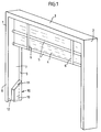
- FIG. 1 there is shown the left half of a door to which the invention can be applied. It comprises two lateral uprights, 1 and 2, joined at their upper parts by a cross member 3.
- the assembly forms a gantry which is arranged around a bay formed in a wall.
- the opening can be closed by a curtain 4 reinforced by reinforcing bars 5.
- One end of the curtain is fixed at the top of the door, in the span 3.
- the curtain is reinforced by reinforcing bars 5 whose ends slide in slides formed in the side uprights.
- straps 6 are fixed to the lower bar, and can be wrapped around a shaft arranged in the upper cross member, with the mechanical and electrical actuation and control means.
- each slide has a bottom, a first guigade wall 8 and a second guide wall 9.
- the free edges of the guide walls can have single or multiple folds, towards the inside of the slide, to stiffen it or improve the sliding by removing a cutting edge. For the sake of clarity, these folds do not interfere with the present invention, have not been shown in the drawings.
- the slide must be wide enough, at least at the top, and up to a certain height from the bottom, to allow during the lifting of the curtain, the accumulation of the folded edges of the curtain and the ends of the reinforcing bars . But when the curtain is down, it should be held as best as possible possible to avoid beating. In the lower part, corresponding to the two or three lower bars, when the curtain is lowered, the slide is therefore made more narrowly.
- a filling element 10 comprising a guide ramp having a guide surface 11A and a placement surface 11B, opposite of the first guide wall 8 of the slide, to define therewith, a placement volume 12 narrowed downward, to receive the curtain with the lower bar (s) with reduced play.
- the lower part of the curtain is therefore pressed towards the first guide wall of the slide. It will therefore be necessary to place the guide ramp, depending on the conditions, in particular the wind, which apply the curtain on one side more than the other.
- the guide ramp forms an angle between the guide surface and the placement surface. It may as well be curved, or polygonal.
- the surface 11A, 11B can be produced by a strip of welded sheet metal. If an unforeseen, accidental push, or under the effect of a draft, gust, etc., the lower bar bends and its end comes under the sheet metal strip 11, during the next raising of the curtain, the bar will be torn off, and the curtain destroyed. If the guide ramp is completed towards the outside of the slide by a solid surface 13, which will be designated below as the clearance surface, the same risk remains. Indeed, under the effect of an abnormal push, the lower bar can come out of the placement volume 12 and come to coincide in bracing against the surface 13 and on the next ascent, the curtain will tear.
- the invention aims to eliminate this risk.
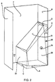
- the invention is shown in detail in Figure 2 which shows on a larger scale the bottom of a slide, with the bottom 7, the first guide wall 8 and the second guide wall 9.
- a filling element 20 according to l The invention has been arranged in place of the conventional element 10 in FIG. 1.
- the filling element 20 has a clearance surface 23 which is inclined upwards towards the bottom of the slide.
- the angle of inclination, which appears at A on the right side of the figure is advantageously between approximately 1 and 10 degrees, preferably between 2 and 4 degrees, exceptionally more for very large doors. A too weak, insensitive inclination would be ineffective, and an too strong inclination would excessively reduce the width L of the ramp at its upper part.
- the clearance surface 23 is also inclined horizontally from the edge of the element in contact with the second guide wall 9, towards the bottom of the slide, at a similar angle B, which appears at the bottom of the figure.
- the aim of this inclination is to allow the loosening in case of wind pushing the curtain towards the first wall 8.
- the release surface can be flat, or curved, that is to say have variable angles of inclination.
- the placement surface 24 is deviated horizontally by an angle C, from the bottom of the slide, towards the second guide wall, so that the placement volume 22 is flared horizontally from the bottom of the slide.
- the upper guide surface 27 is also advantageously inclined downwards by an angle D which can be of the same order of magnitude.
- guide surface 21 and the placement surface 24 may form a dihedral angle, as shown in Figure 2, or be connected by a polygonal or rounded outline.
- the set of surfaces 21, 23 and 24 is made up of a single piece, preferably made of molded plastic, which allows simple and safe installation and easy storage by nesting. , which is allowed by the flared shapes of this guide ramp.
- the presence of the filling element is used to place inside a security device, such as an emitting or receiving cell of an appropriate radius, (infrared, laser , etc) one of the elements carrying the transmitter, the other the receiver.
- a security device such as an emitting or receiving cell of an appropriate radius, (infrared, laser , etc) one of the elements carrying the transmitter, the other the receiver.
- a hole 25 is provided in the clearance surface 23.
- FIGS. 3 and 4 show an alternative application. Doors of this type can be used in food or pharmaceutical warehouses. In such applications, dead or inaccessible volumes should be removed as much as possible. Dirt can lodge there and bacteria can grow.
- the presence of the guide ramp according to the invention defines a closed volume at the bottom of the upright. This volume is not accessible for cleaning (water jet).
- the part of the bottom of the upright, delimited by the guide ramp is cut out, to produce an opening 7A having the same profile as the guide ramp. It is thus possible to jet clean the interior of this cavity and ensure a cleanliness preventing the development of bacteria.
- This quality can be further improved by providing a window 26 at the lower part of the clearance surface 23, which further facilitates the evacuation of the washing water to avoid stagnation.
Landscapes
- Engineering & Computer Science (AREA)
- Structural Engineering (AREA)
- Architecture (AREA)
- Civil Engineering (AREA)
- Operating, Guiding And Securing Of Roll- Type Closing Members (AREA)
- Securing Of Glass Panes Or The Like (AREA)
- Tents Or Canopies (AREA)
- Curtains And Furnishings For Windows Or Doors (AREA)
- Elevator Door Apparatuses (AREA)
- Wing Frames And Configurations (AREA)
- Special Wing (AREA)
Applications Claiming Priority (2)
| Application Number | Priority Date | Filing Date | Title |
|---|---|---|---|
| FR9102346 | 1991-02-27 | ||
| FR9102346A FR2673235B1 (fr) | 1991-02-27 | 1991-02-27 | Dispositif de securite contre les coincements pour porte de manutention du type a rideau avec barres d'armatures. |
Publications (2)
| Publication Number | Publication Date |
|---|---|
| EP0501841A1 EP0501841A1 (fr) | 1992-09-02 |
| EP0501841B1 true EP0501841B1 (fr) | 1995-04-19 |
Family
ID=9410156
Family Applications (1)
| Application Number | Title | Priority Date | Filing Date |
|---|---|---|---|
| EP92400108A Expired - Lifetime EP0501841B1 (fr) | 1991-02-27 | 1992-01-15 | Dispositif de sécurité contre les coincements pour porte de manutention du type à rideau avec barres d'armatures |
Country Status (10)
| Country | Link |
|---|---|
| US (1) | US5209281A (cs) |
| EP (1) | EP0501841B1 (cs) |
| JP (1) | JPH0579262A (cs) |
| AT (1) | ATE121495T1 (cs) |
| AU (1) | AU1109692A (cs) |
| CA (1) | CA2061503A1 (cs) |
| CZ (1) | CZ58392A3 (cs) |
| DE (1) | DE69202082T2 (cs) |
| FR (1) | FR2673235B1 (cs) |
| HU (1) | HUT60837A (cs) |
Families Citing this family (13)
| Publication number | Priority date | Publication date | Assignee | Title |
|---|---|---|---|---|
| US5575322A (en) * | 1995-09-15 | 1996-11-19 | Miller; James V. | Rolling protective shutters |
| FR2744485B1 (fr) * | 1996-02-02 | 1998-04-10 | Nergeco Sa | Porte de manutention a etancheite renforcee |
| US6085822A (en) * | 1997-02-20 | 2000-07-11 | Miller; James V. | Deployment control for rolling protective shutters |
| US5850862A (en) * | 1997-02-20 | 1998-12-22 | Miller; James V. | Rolling protective shutters |
| GB2348233B (en) * | 1999-03-24 | 2001-07-18 | Waivis Ltd | Shutter centre stop |
| US7100665B2 (en) * | 2004-03-17 | 2006-09-05 | Miller James V | Dual boss shutter slat with retention plate |
| US7357171B2 (en) | 2004-03-17 | 2008-04-15 | Qmi Security Solutions | Low-clearance shutter slat |
| US7784522B2 (en) * | 2004-03-17 | 2010-08-31 | Qualitas Manufacturing Incorporated | Locator and shutter slat |
| WO2013126470A1 (en) | 2012-02-20 | 2013-08-29 | Miller James V | Improved shutter slat and compact shutter assembly |
| US10465440B2 (en) | 2012-02-20 | 2019-11-05 | Qualitas Manufacturing Incorporated | Shutter slat |
| WO2013126453A2 (en) | 2012-02-20 | 2013-08-29 | Qualitas Manufacturing Incorporated | Improved shutter slat |
| US9945178B2 (en) * | 2015-06-26 | 2018-04-17 | Performax Global | Flexible door assembly |
| JP6517646B2 (ja) * | 2015-09-24 | 2019-05-22 | アイシン精機株式会社 | シェード装置 |
Family Cites Families (4)
| Publication number | Priority date | Publication date | Assignee | Title |
|---|---|---|---|---|
| AT315450B (de) * | 1971-07-22 | 1974-05-27 | Aeberli Kurt | Rolladen |
| DE2206789C3 (de) * | 1972-02-12 | 1974-07-25 | Pade, Guenter Julius Andreas, 6350 Bad Nauheim | Fütterungsleiste für Führungsschienen von Rolläden aus Metall |
| CH624732A5 (en) * | 1976-11-02 | 1981-08-14 | Richard Froehlich | Device for locking roller shutters |
| FR2488646A1 (fr) * | 1980-08-12 | 1982-02-19 | Kraeutler Bernard | Panneau de remplissage de portes dites en accordeon |
-
1991
- 1991-02-27 FR FR9102346A patent/FR2673235B1/fr not_active Expired - Fee Related
-
1992
- 1992-01-15 EP EP92400108A patent/EP0501841B1/fr not_active Expired - Lifetime
- 1992-01-15 DE DE69202082T patent/DE69202082T2/de not_active Expired - Fee Related
- 1992-01-15 AT AT92400108T patent/ATE121495T1/de active
- 1992-02-13 US US07/836,209 patent/US5209281A/en not_active Expired - Lifetime
- 1992-02-19 HU HU9200533A patent/HUT60837A/hu unknown
- 1992-02-19 CA CA002061503A patent/CA2061503A1/en not_active Abandoned
- 1992-02-19 AU AU11096/92A patent/AU1109692A/en not_active Abandoned
- 1992-02-27 CZ CS92583A patent/CZ58392A3/cs unknown
- 1992-02-27 JP JP4075640A patent/JPH0579262A/ja not_active Withdrawn
Also Published As
| Publication number | Publication date |
|---|---|
| FR2673235A1 (fr) | 1992-08-28 |
| AU1109692A (en) | 1992-09-03 |
| JPH0579262A (ja) | 1993-03-30 |
| EP0501841A1 (fr) | 1992-09-02 |
| FR2673235B1 (fr) | 1994-01-28 |
| US5209281A (en) | 1993-05-11 |
| HU9200533D0 (en) | 1992-05-28 |
| CZ58392A3 (en) | 1993-05-12 |
| ATE121495T1 (de) | 1995-05-15 |
| DE69202082D1 (de) | 1995-05-24 |
| CA2061503A1 (en) | 1992-08-28 |
| HUT60837A (en) | 1992-10-28 |
| DE69202082T2 (de) | 1995-09-28 |
Similar Documents
| Publication | Publication Date | Title |
|---|---|---|
| EP0501841B1 (fr) | Dispositif de sécurité contre les coincements pour porte de manutention du type à rideau avec barres d'armatures | |
| EP0476788B1 (fr) | Porte à rideau relevable | |
| EP0540110B1 (fr) | Porte à rideau relevable à isolation thermique renforcée | |
| WO2001053648A1 (fr) | Lames semi-rigides pour porte de manutention a rideau souple | |
| EP0542338B1 (fr) | Porte de manutention à rideau relevable étanche | |
| CH649125A5 (fr) | Huisserie de porte paliere d'ascenseur. | |
| EP0502758B1 (fr) | Dispositif d'étanchéité amovible pour porte de manutention à rideau relevable | |
| EP2112321A1 (fr) | Volet roulant équipé d'un frein, frein et lame de freinage pour un tel volet | |
| EP0502772A1 (fr) | Patin de glissement pour porte de manutention à rideau relevable | |
| EP0801183A1 (fr) | Exutoire de désenfumage pour une voûte cintrée allongée | |
| FR2582702A1 (fr) | Plancher pour echafaudages muni d'une trappe d'acces amovible a deux battants | |
| EP0717807B1 (fr) | Porte de manutention | |
| EP1090205B1 (fr) | Porte de manutention | |
| EP1524399A1 (fr) | Portillon de sécurité | |
| FR2683258A1 (fr) | Porte de manutention a rideau relevable a etancheite laterale amelioree. | |
| FR2547856A1 (fr) | Procede et dispositif de fermeture de baies, utilisant un tablier se deplacant dans des coulisses | |
| FR2873400A1 (fr) | Ensemble de lames articulees, tablier de volet roulant et volet roulant ainsi forme | |
| EP0690200B1 (fr) | Dispositif de blocage pour volet roulant | |
| EP0487436B1 (fr) | Caisson de volet roulant | |
| FR2768164A1 (fr) | Lanterneau de securite et/ou d'eclairage | |
| EP1357242A1 (fr) | Elément de barrière à montage simplifié, barrière comprenant un tel élément et procédé d'assemblage d'un tel ensemble | |
| CH598467A5 (en) | Outside window shutter | |
| FR2618468A1 (fr) | Couvercle pour regard ou analogue | |
| BE1011418A4 (fr) | Cadre ouvrant. | |
| EP1533464B1 (fr) | Dispositif de guidage à profil limitant la fuite d'air pour porte de manutention |
Legal Events
| Date | Code | Title | Description |
|---|---|---|---|
| PUAI | Public reference made under article 153(3) epc to a published international application that has entered the european phase |
Free format text: ORIGINAL CODE: 0009012 |
|
| AK | Designated contracting states |
Kind code of ref document: A1 Designated state(s): AT BE CH DE DK ES FR GB GR IT LI LU MC NL PT SE |
|
| 17P | Request for examination filed |
Effective date: 19930219 |
|
| 17Q | First examination report despatched |
Effective date: 19940916 |
|
| GRAA | (expected) grant |
Free format text: ORIGINAL CODE: 0009210 |
|
| AK | Designated contracting states |
Kind code of ref document: B1 Designated state(s): AT BE CH DE DK ES FR GB GR IT LI LU MC NL PT SE |
|
| PG25 | Lapsed in a contracting state [announced via postgrant information from national office to epo] |
Ref country code: NL Free format text: LAPSE BECAUSE OF FAILURE TO SUBMIT A TRANSLATION OF THE DESCRIPTION OR TO PAY THE FEE WITHIN THE PRESCRIBED TIME-LIMIT Effective date: 19950419 Ref country code: MC Free format text: LAPSE BECAUSE OF NON-PAYMENT OF DUE FEES Effective date: 19950419 Ref country code: GR Free format text: LAPSE BECAUSE OF FAILURE TO SUBMIT A TRANSLATION OF THE DESCRIPTION OR TO PAY THE FEE WITHIN THE PRESCRIBED TIME-LIMIT Effective date: 19950419 Ref country code: ES Free format text: THE PATENT HAS BEEN ANNULLED BY A DECISION OF A NATIONAL AUTHORITY Effective date: 19950419 Ref country code: DK Effective date: 19950419 Ref country code: AT Effective date: 19950419 |
|
| REF | Corresponds to: |
Ref document number: 121495 Country of ref document: AT Date of ref document: 19950515 Kind code of ref document: T |
|
| REF | Corresponds to: |
Ref document number: 69202082 Country of ref document: DE Date of ref document: 19950524 |
|
| ITF | It: translation for a ep patent filed | ||
| GBT | Gb: translation of ep patent filed (gb section 77(6)(a)/1977) |
Effective date: 19950517 |
|
| PG25 | Lapsed in a contracting state [announced via postgrant information from national office to epo] |
Ref country code: SE Effective date: 19950719 Ref country code: PT Effective date: 19950719 |
|
| NLV1 | Nl: lapsed or annulled due to failure to fulfill the requirements of art. 29p and 29m of the patents act | ||
| PG25 | Lapsed in a contracting state [announced via postgrant information from national office to epo] |
Ref country code: LU Free format text: LAPSE BECAUSE OF NON-PAYMENT OF DUE FEES Effective date: 19960131 Ref country code: BE Effective date: 19960131 |
|
| PLBE | No opposition filed within time limit |
Free format text: ORIGINAL CODE: 0009261 |
|
| STAA | Information on the status of an ep patent application or granted ep patent |
Free format text: STATUS: NO OPPOSITION FILED WITHIN TIME LIMIT |
|
| 26N | No opposition filed | ||
| BERE | Be: lapsed |
Owner name: S.A. NERGECO Effective date: 19960131 |
|
| REG | Reference to a national code |
Ref country code: CH Ref legal event code: PL |
|
| REG | Reference to a national code |
Ref country code: CH Ref legal event code: AEN Free format text: LA POURSUITE DE LA PROCEDURE REQUISE LE 01.10.1996 A ETE ACCORDEE. LE BREVET EST REACTIVE. |
|
| REG | Reference to a national code |
Ref country code: CH Ref legal event code: NV Representative=s name: BOVARD AG PATENTANWAELTE |
|
| PGFP | Annual fee paid to national office [announced via postgrant information from national office to epo] |
Ref country code: GB Payment date: 20001212 Year of fee payment: 10 |
|
| PGFP | Annual fee paid to national office [announced via postgrant information from national office to epo] |
Ref country code: CH Payment date: 20001214 Year of fee payment: 10 |
|
| PGFP | Annual fee paid to national office [announced via postgrant information from national office to epo] |
Ref country code: DE Payment date: 20010102 Year of fee payment: 10 |
|
| PGFP | Annual fee paid to national office [announced via postgrant information from national office to epo] |
Ref country code: FR Payment date: 20010129 Year of fee payment: 10 |
|
| REG | Reference to a national code |
Ref country code: GB Ref legal event code: IF02 |
|
| PG25 | Lapsed in a contracting state [announced via postgrant information from national office to epo] |
Ref country code: GB Free format text: LAPSE BECAUSE OF NON-PAYMENT OF DUE FEES Effective date: 20020115 |
|
| PG25 | Lapsed in a contracting state [announced via postgrant information from national office to epo] |
Ref country code: LI Free format text: LAPSE BECAUSE OF NON-PAYMENT OF DUE FEES Effective date: 20020131 Ref country code: CH Free format text: LAPSE BECAUSE OF NON-PAYMENT OF DUE FEES Effective date: 20020131 |
|
| PG25 | Lapsed in a contracting state [announced via postgrant information from national office to epo] |
Ref country code: DE Free format text: LAPSE BECAUSE OF NON-PAYMENT OF DUE FEES Effective date: 20020801 |
|
| GBPC | Gb: european patent ceased through non-payment of renewal fee |
Effective date: 20020115 |
|
| REG | Reference to a national code |
Ref country code: CH Ref legal event code: PL |
|
| PG25 | Lapsed in a contracting state [announced via postgrant information from national office to epo] |
Ref country code: FR Free format text: LAPSE BECAUSE OF NON-PAYMENT OF DUE FEES Effective date: 20020930 |
|
| REG | Reference to a national code |
Ref country code: FR Ref legal event code: ST |
|
| PG25 | Lapsed in a contracting state [announced via postgrant information from national office to epo] |
Ref country code: IT Free format text: LAPSE BECAUSE OF NON-PAYMENT OF DUE FEES;WARNING: LAPSES OF ITALIAN PATENTS WITH EFFECTIVE DATE BEFORE 2007 MAY HAVE OCCURRED AT ANY TIME BEFORE 2007. THE CORRECT EFFECTIVE DATE MAY BE DIFFERENT FROM THE ONE RECORDED. Effective date: 20050115 |