EP0501437A2 - Vorrichtung zum Festlegen von Parametern für eine Motorregeleinheit - Google Patents
Vorrichtung zum Festlegen von Parametern für eine Motorregeleinheit Download PDFInfo
- Publication number
- EP0501437A2 EP0501437A2 EP92103246A EP92103246A EP0501437A2 EP 0501437 A2 EP0501437 A2 EP 0501437A2 EP 92103246 A EP92103246 A EP 92103246A EP 92103246 A EP92103246 A EP 92103246A EP 0501437 A2 EP0501437 A2 EP 0501437A2
- Authority
- EP
- European Patent Office
- Prior art keywords
- parameter
- conversion rule
- signal
- address
- providing
- Prior art date
- Legal status (The legal status is an assumption and is not a legal conclusion. Google has not performed a legal analysis and makes no representation as to the accuracy of the status listed.)
- Granted
Links
Images

Classifications
-
- H—ELECTRICITY
- H02—GENERATION; CONVERSION OR DISTRIBUTION OF ELECTRIC POWER
- H02P—CONTROL OR REGULATION OF ELECTRIC MOTORS, ELECTRIC GENERATORS OR DYNAMO-ELECTRIC CONVERTERS; CONTROLLING TRANSFORMERS, REACTORS OR CHOKE COILS
- H02P23/00—Arrangements or methods for the control of AC motors characterised by a control method other than vector control
- H02P23/0077—Characterised by the use of a particular software algorithm
Definitions
- the invention relates to a parameter setting apparatus to select, change, or set an operation and a function of a motor control unit.
- variable speed motors whose speed is variably controlled by a servo driver or an inverter are increasing and are becoming various due to the rapid development of the power electronics, micro electronics, and the like.
- a parameter setting apparatus comprises parameter selecting means 1, parameter setting means 2, parameter storing means 3, and address converting means 4.
- the parameter selecting means 1 is constructed by rotary switches which can directly designate the kinds and number of parameters, a ten-key composed of keys "0" to "9", keys to instruct an increase and a decrease of the contents of the parameters, or the like.
- the parameter setting means 2 is also constructed by a ten-key, keys to instruct the increase and decrease, variable resistors to indicate the contents of the parameters in an analog manner, or the like.
- the parameter storing means 3 comprises a non-volatile memory such as an EEPROM (electrically erasable programable read-only memory) or the like and addresses for the necessary parameters are obtained by converting an output of the parameter selecting means 1 by the address converting means 4.
- EEPROM electrically erasable programable read-only memory
- the address converting means 4 converts the output of the parameter selecting means 1 into the address in the parameter storing means 3 by executing calculating equations after simply multiplying by an integer or using the output as it is, for instance, or by using a conversion table, or the like.
- the invention is made to solve the above problems and it is an object of the invention to provide a parameter setting apparatus for a motor control unit in which the positions of the parameters can be rearranged so that the significant parameter having a high use frequency can be easily selected in accordance with each application field.
- a parameter setting apparatus for a motor control unit comprising: parameter storing means; parameter selecting means; address converting means for converting an output of the parameter selecting means into an address of the parameter storing means; parameter setting means for setting the content in the parameter storing means designated by the address converting means; conversion rule storing means for designating an address converting method; conversion rule selecting means for updating the content stored in the conversion rule storing means; and conversion rule setting means, wherein the content in the conversion rule storing means is set by the conversion rule selecting means and the conversion rule setting means.
- the parameter setting apparatus for the invention handles the address conversion rule as one kind of parameters and the apparatus may arbitrarily connect the parameter selecting means with the address of the parameter storing means, so that the parameter having a high use frequency or the like can be rearranged to be easily selected in accordance with each application field.
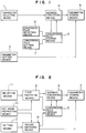
- Fig. 1 is a block diagram showing a parameter setting apparatus for a motor control unit according to the first embodiment of the invention.
- reference numeral 1 denotes the parameter selecting means for selecting kinds and numbers of parameters to be set; 2 the parameter setting means for setting values of the selected parameters; 3 the parameter storing means for recording the set parameters; 4 the address converting means for obtaining address of storing location for the parameters; 5 conversion rule storing means for designating a method for address conversion used in the address converting means 4; 6 conversion rule selecting means for designating a specific rule from a plurality of conversion rules; and 7 conversion rule setting means for setting the content of the specific conversion rule designated by the conversion rule selecting means 6.
- the construction of Fig. 1 differs from the conventional construction of Fig.
- Figs. 3A and 3B are memory maps for explaining constructions and operations of the parameter storing means 3 and the conversion rule storing means 5 in the case where the number of parameters is set to five for easy understanding.
- the parameter storing means 3 and the conversion rule storing means 5 comprise one non-volatile memory 51 having addresses "0" to "9".
- the parameter storing means 3 is allocated to areas of addresses “0" to "4" and five parameters are stored into the respective addresses one by one.
- the conversion rule storing means 5 has a conversion table allocated to areas of addresses "5" to "9” and the addresses in the parameter storing means 3 are stored in those areas.
- Fig. 3A shows a state before the parameters are rearranged.
- the address converting means 4 adds an output of the parameter selecting means 1 with a bias value ("5" in the embodiment) in the conversion rule storing means 5.
- the resultant value is subsequently used as an address and data is read from the non-volatile memory 51 according to the address.
- the parameters are not rearranged and the value of the data is equal to the value which is derived by subtracting the bias from the address, so that the value coincides with the output of the parameter selecting means 1.
- the address conversion rule in the address converting means 4 can be determined by the content of the conversion rule storing means 5.
- the user can arbitrarily decide such a content by using the conversion rule selecting means 6 and the conversion rule setting means 7 and each user can optimally rearrange the parameters. It is, therefore, possible to provide the parameter setting apparatus for a motor control unit which can be easily used even when the number of parameters increases.
- Fig. 2 is a block diagram showing a parameter setting apparatus for a motor control unit of the second embodiment of the invention.
- reference numeral 11 denotes the selecting means for selecting parameters or addresses; 12 the setting means for setting contents of the parameters or addresses; 3 the parameter storing means; 4 the address converting means; 5 the conversion rule storing means; 10 set mode instructing means for instructing either a mode to set the content of the parameter storing means 3 or a mode to set the content of the conversion rule storing means 5; 8 the first switching means for transferring the output of the selecting means 11 to either the address converting means 4 or the conversion rule storing means 5 in accordance with the set mode; and 9 the second switching means for setting a target of the setting means 12 to either the parameter storing means 3 or the conversion rule storing means 5 in accordance with the set mode.
- the second embodiment differs from the construction of the first embodiment described in reference to Fig. 1 with respect to the following points. That is, the conversion rule selecting means 6 and the conversion rule setting means 7 in Fig. 1 are not provided as independent means, but the first switching means 8, the second switching means 9, and the set mode instructing means 10 are provided, and the selecting means 11 and the setting means 12 are provided to be commonly used for the parameter storing means 3 and the converting rule storing means 5.
- the selecting means 11 is connected to the address converting means 4 through the first switching means 8, while the setting means 12 is connected to the parameter storing means 3 through the second switching means 9.
- the selecting means 11 is connected to the conversion rule storing means 5 through the first switching means 8, while the setting means 12 is connected to the conversion rule storing means 5 through the second switching means 9. Therefore, when the parameter setting device of the second embodiment rearranges the parameters, the set mode instructing means 10 instructs a mode to set the conversion rule, and the first selecting means 11 and the setting means 12 are used for setting the contents of the converting rule storing means 5.
- the parameters can be rearranged by using the selecting means 11 and the setting means 12 without separately providing the conversion rule selecting means 6 and the conversion rule setting means 7 in Fig. 1. Consequently, it is possible to provide the parameter setting apparatus for a motor control unit which can be easily operated even when the number of parameters increases.
- the user decides the conversion rule storing means for determining the converting method of converting the output of the parameter selecting means into the address in the parameter storing means and can rearrange the parameters. Therefore, even when the number of parameters increases, only the parameters which are necessary for the user can be collected and accessed, and the parameter setting apparatus for a motor control unit which can be easily used can be provided.
Landscapes
- Engineering & Computer Science (AREA)
- Power Engineering (AREA)
- Control Of Electric Motors In General (AREA)
- Feedback Control In General (AREA)
Applications Claiming Priority (2)
| Application Number | Priority Date | Filing Date | Title |
|---|---|---|---|
| JP3032823A JPH04271402A (ja) | 1991-02-27 | 1991-02-27 | モータ制御装置のパラメータ設定器 |
| JP32823/91 | 1991-02-27 |
Publications (3)
| Publication Number | Publication Date |
|---|---|
| EP0501437A2 true EP0501437A2 (de) | 1992-09-02 |
| EP0501437A3 EP0501437A3 (en) | 1993-03-24 |
| EP0501437B1 EP0501437B1 (de) | 1995-11-08 |
Family
ID=12369553
Family Applications (1)
| Application Number | Title | Priority Date | Filing Date |
|---|---|---|---|
| EP92103246A Expired - Lifetime EP0501437B1 (de) | 1991-02-27 | 1992-02-26 | Vorrichtung zum Festlegen von Parametern für eine Motorregeleinheit |
Country Status (3)
| Country | Link |
|---|---|
| EP (1) | EP0501437B1 (de) |
| JP (1) | JPH04271402A (de) |
| DE (1) | DE69205857T2 (de) |
Cited By (1)
| Publication number | Priority date | Publication date | Assignee | Title |
|---|---|---|---|---|
| CN100359796C (zh) * | 2002-06-19 | 2008-01-02 | 波峰实验室责任有限公司 | 用于动态改变电机赋能电流的波形曲线的电机控制系统 |
-
1991
- 1991-02-27 JP JP3032823A patent/JPH04271402A/ja active Pending
-
1992
- 1992-02-26 EP EP92103246A patent/EP0501437B1/de not_active Expired - Lifetime
- 1992-02-26 DE DE69205857T patent/DE69205857T2/de not_active Expired - Fee Related
Cited By (1)
| Publication number | Priority date | Publication date | Assignee | Title |
|---|---|---|---|---|
| CN100359796C (zh) * | 2002-06-19 | 2008-01-02 | 波峰实验室责任有限公司 | 用于动态改变电机赋能电流的波形曲线的电机控制系统 |
Also Published As
| Publication number | Publication date |
|---|---|
| EP0501437B1 (de) | 1995-11-08 |
| JPH04271402A (ja) | 1992-09-28 |
| DE69205857T2 (de) | 1996-07-04 |
| EP0501437A3 (en) | 1993-03-24 |
| DE69205857D1 (de) | 1995-12-14 |
Similar Documents
| Publication | Publication Date | Title |
|---|---|---|
| EP0501437B1 (de) | Vorrichtung zum Festlegen von Parametern für eine Motorregeleinheit | |
| JPH023874A (ja) | データメモリに格納される道路網地図のための重要なデータを求めて記憶する方法 | |
| US5157784A (en) | Memory control system responsive to determination, allocating adjacent test space for editing space, relocating adjacent text and editing selected text | |
| US5028923A (en) | ISO/EIA code converting method | |
| JPH01176113A (ja) | ディジタル信号処理装置 | |
| US4727288A (en) | Digital wave observation apparatus | |
| JPH04344902A (ja) | 制御装置のパラメータ設定器 | |
| JP3004683B2 (ja) | 電子楽器 | |
| JPH0511803A (ja) | モータ制御装置のパラメータ設定器 | |
| JP3767646B2 (ja) | 電動機制御定数の設定記憶装置を備えた電動機制御装置 | |
| JPH0334304B2 (de) | ||
| JP2796217B2 (ja) | データ伝送装置 | |
| JPS581262A (ja) | メモリアドレス制御方式 | |
| JPH0137754B2 (de) | ||
| JPS58146295U (ja) | パラメ−タ設定装置 | |
| JP3006977B2 (ja) | 電子楽器の演奏制御情報設定装置 | |
| JPH0637339Y2 (ja) | 波形記憶装置 | |
| JP2739206B2 (ja) | ファクシミリ装置 | |
| JPH0313767Y2 (de) | ||
| JPH0243361B2 (de) | ||
| JPH0583143A (ja) | データ変換装置 | |
| JPS6368920A (ja) | 端末装置 | |
| JPS622643Y2 (de) | ||
| JPH0739086Y2 (ja) | Fddコントロ−ル回路 | |
| JPH0563448A (ja) | 波形発生装置 |
Legal Events
| Date | Code | Title | Description |
|---|---|---|---|
| PUAI | Public reference made under article 153(3) epc to a published international application that has entered the european phase |
Free format text: ORIGINAL CODE: 0009012 |
|
| AK | Designated contracting states |
Kind code of ref document: A2 Designated state(s): DE GB |
|
| PUAL | Search report despatched |
Free format text: ORIGINAL CODE: 0009013 |
|
| AK | Designated contracting states |
Kind code of ref document: A3 Designated state(s): DE GB |
|
| 17P | Request for examination filed |
Effective date: 19930512 |
|
| 17Q | First examination report despatched |
Effective date: 19950216 |
|
| GRAA | (expected) grant |
Free format text: ORIGINAL CODE: 0009210 |
|
| AK | Designated contracting states |
Kind code of ref document: B1 Designated state(s): DE GB |
|
| REF | Corresponds to: |
Ref document number: 69205857 Country of ref document: DE Date of ref document: 19951214 |
|
| PLBE | No opposition filed within time limit |
Free format text: ORIGINAL CODE: 0009261 |
|
| STAA | Information on the status of an ep patent application or granted ep patent |
Free format text: STATUS: NO OPPOSITION FILED WITHIN TIME LIMIT |
|
| 26N | No opposition filed | ||
| REG | Reference to a national code |
Ref country code: GB Ref legal event code: IF02 |
|
| PGFP | Annual fee paid to national office [announced via postgrant information from national office to epo] |
Ref country code: GB Payment date: 20060222 Year of fee payment: 15 |
|
| PGFP | Annual fee paid to national office [announced via postgrant information from national office to epo] |
Ref country code: DE Payment date: 20060223 Year of fee payment: 15 |
|
| GBPC | Gb: european patent ceased through non-payment of renewal fee |
Effective date: 20070226 |
|
| PG25 | Lapsed in a contracting state [announced via postgrant information from national office to epo] |
Ref country code: DE Free format text: LAPSE BECAUSE OF NON-PAYMENT OF DUE FEES Effective date: 20070901 |
|
| PG25 | Lapsed in a contracting state [announced via postgrant information from national office to epo] |
Ref country code: GB Free format text: LAPSE BECAUSE OF NON-PAYMENT OF DUE FEES Effective date: 20070226 |