EP0500566B1 - Procede et appareil de construction d'une ile artificielle et construction ainsi obtenue - Google Patents
Procede et appareil de construction d'une ile artificielle et construction ainsi obtenue Download PDFInfo
- Publication number
- EP0500566B1 EP0500566B1 EP90915464A EP90915464A EP0500566B1 EP 0500566 B1 EP0500566 B1 EP 0500566B1 EP 90915464 A EP90915464 A EP 90915464A EP 90915464 A EP90915464 A EP 90915464A EP 0500566 B1 EP0500566 B1 EP 0500566B1
- Authority
- EP
- European Patent Office
- Prior art keywords
- pontoons
- construction
- water
- wall
- ring
- Prior art date
- Legal status (The legal status is an assumption and is not a legal conclusion. Google has not performed a legal analysis and makes no representation as to the accuracy of the status listed.)
- Expired - Lifetime
Links
- 238000000034 method Methods 0.000 title claims abstract description 26
- 238000010276 construction Methods 0.000 title claims description 165
- XLYOFNOQVPJJNP-UHFFFAOYSA-N water Substances O XLYOFNOQVPJJNP-UHFFFAOYSA-N 0.000 claims abstract description 62
- 238000004519 manufacturing process Methods 0.000 claims abstract description 29
- 238000007667 floating Methods 0.000 claims abstract description 16
- 238000006073 displacement reaction Methods 0.000 claims description 10
- 230000009194 climbing Effects 0.000 claims description 7
- 230000008878 coupling Effects 0.000 claims description 6
- 238000010168 coupling process Methods 0.000 claims description 6
- 238000005859 coupling reaction Methods 0.000 claims description 6
- 230000000284 resting effect Effects 0.000 claims description 3
- 239000000463 material Substances 0.000 claims description 2
- 230000000295 complement effect Effects 0.000 claims 1
- 241000826860 Trapezium Species 0.000 description 5
- 239000004576 sand Substances 0.000 description 5
- 239000000126 substance Substances 0.000 description 5
- 230000002787 reinforcement Effects 0.000 description 3
- 238000005553 drilling Methods 0.000 description 2
- 238000005452 bending Methods 0.000 description 1
- 239000011796 hollow space material Substances 0.000 description 1
- 238000009434 installation Methods 0.000 description 1
- 238000011835 investigation Methods 0.000 description 1
- 238000005086 pumping Methods 0.000 description 1
- 230000003014 reinforcing effect Effects 0.000 description 1
- 238000005096 rolling process Methods 0.000 description 1
Images


Classifications
-
- E—FIXED CONSTRUCTIONS
- E02—HYDRAULIC ENGINEERING; FOUNDATIONS; SOIL SHIFTING
- E02B—HYDRAULIC ENGINEERING
- E02B17/00—Artificial islands mounted on piles or like supports, e.g. platforms on raisable legs or offshore constructions; Construction methods therefor
- E02B17/02—Artificial islands mounted on piles or like supports, e.g. platforms on raisable legs or offshore constructions; Construction methods therefor placed by lowering the supporting construction to the bottom, e.g. with subsequent fixing thereto
- E02B17/027—Artificial islands mounted on piles or like supports, e.g. platforms on raisable legs or offshore constructions; Construction methods therefor placed by lowering the supporting construction to the bottom, e.g. with subsequent fixing thereto steel structures
-
- E—FIXED CONSTRUCTIONS
- E02—HYDRAULIC ENGINEERING; FOUNDATIONS; SOIL SHIFTING
- E02B—HYDRAULIC ENGINEERING
- E02B17/00—Artificial islands mounted on piles or like supports, e.g. platforms on raisable legs or offshore constructions; Construction methods therefor
- E02B17/0017—Means for protecting offshore constructions
- E02B17/0021—Means for protecting offshore constructions against ice-loads
-
- E—FIXED CONSTRUCTIONS
- E02—HYDRAULIC ENGINEERING; FOUNDATIONS; SOIL SHIFTING
- E02D—FOUNDATIONS; EXCAVATIONS; EMBANKMENTS; UNDERGROUND OR UNDERWATER STRUCTURES
- E02D23/00—Caissons; Construction or placing of caissons
- E02D23/02—Caissons able to be floated on water and to be lowered into water in situ
-
- E—FIXED CONSTRUCTIONS
- E02—HYDRAULIC ENGINEERING; FOUNDATIONS; SOIL SHIFTING
- E02B—HYDRAULIC ENGINEERING
- E02B17/00—Artificial islands mounted on piles or like supports, e.g. platforms on raisable legs or offshore constructions; Construction methods therefor
- E02B2017/0039—Methods for placing the offshore structure
Definitions
- the invention in the first place relates to a method of manufacturing an artificial construction on the bottom of a body of water, such as an artificial island or the like, a column, a pile, a harbour, etc., in which a part of the construction is manufactured at a distance from the final destination in an area which is free from weather conditions, which are disadvantageous for the work, and in which said part of the construction, after completion, is moved in floating condition towards its destination and there lowered upon the bottom of the body of water, said method comprising: first the manufacturing in the dry of pontoons, forming a working platform from the pontoons by interconnecting a number of pontoons in floatable condition such that one end of a pontoon is connected to the opposite end of the next pontoon such that they define an open space at the location of which the lower part of the said artificial construction is made with own buoyancy, which open space, surrounded by the ring of pontoons, has a shape in plan view which is similar in form with the outer circumferential shape of the said artificial
- artificial construction covers arrangements, such as drilling platforms, platforms capable to withstand ice bergs, platforms for investigation or for military purposes.
- Purpose of the invention is to provide a method which is more simple and accordingly more cheap and more flexible with respect to the area where the work has to be done.
- the said lower part of the construction is made on the upper surface of said ring of pontoons which lower part comprises at least the lower portion of said construction, such that the lower edge or base of said construction has a diameter or distance between opposite edge parts respectively, which is larger than the diameter of the inner edge of the circle of pontoons or larger than the distance between opposite inner edges of the pontoons respectively, and that after having completed said lower part the assembly of pontoons and said lower part is floated and moved towards a water depth such that the said lower portion of the construction can float in it with between its lower edge or base and the water bottom a distance which is larger than the height of the pontoons, that thereafter the pontoons are ballasted and moved away from below said part of the construction and subsequently are recovered after which said part of the construction is placed upon the bottom of the body of water and that at least part of the pontoons originally used for carrying said lower portion are placed against the outer wall of the construction and connected therewith in a manner which allows a controllable relevant vertical movement
- the construction starts with the manufacturing of the lower portion of the construction on the top of the ring of pontoons between the side boundaries of said pontoons.
- a ring of pontoons Even if rigidly interconnected, is not a stable platform from which the manufacturing of the construction can be done.
- said pontoons in the beginning of the operation are supported by a rigid surface called the working surface.
- the working surface On the top of said pontoons which due to being supported by the working surface are not subjected to water movements in case water is present in said first stage, the lower part of the construction to be made is manufactured.
- Said lower part resting by its own weight on the pontoons gives sufficient rigidity to the sequence of pontoons such that after being brought in a buoyant condition pontoons and on top of them the lower part of the construction can be floated away to an area of deeper water because the sequence of pontoons now obtains additional rigidity from the already made part of the construction resting upon it.
- This can be a shore area, subjected to tides, in which case one places the pontoons during low tide and are floated when time comes at high tide together with the already manufactured portion of the construction placed upon it.
- the assembly of pontoons and lower portion standing upon it is brought in floating condition or in floating condition respectively towards deeper water, where the pontoons are removed by ballasting and subsequently the floating lower portion, as far as still necessary, is moved towards a place in quiet water where this portion is placed upon the bottom and one continues the assembly of the construction.
- the removed portion then can again be placed around the already manufactured portion and can be coupled therewith and due to this function as working platform.
- the construction can be towed towards the location of destination and there by ballasting and with the aid of means controlling the lowering movement lowered upon the bottom of the sea and subsequently anchored thereto.
- the present invention in particular is destined for very large constructions.
- a simple control of the relative position can be achieved according to the invention in that the coupling in the vertical sense is obtained between pontoons and construction by means of cables, one end of which being connected to the foot of the construction and the other end to winches which are placed upon the pontoons and by means of which from the pontoons cable by cable a controllable tension can be performed.
- An artificial construction of the type meant here and of the dimensions which can be large, may have any desirable circumferential shape, seen in the horizontal plane. This can be a circular circumference, a polygonal circumference, a rectangular circumference, an oval circumference or even the circumference of a harbour having two jetties and an interconnecting portion (U-shape).
- the invention also relates to a device for manufacturing said artificial construction, said device comprising pontoons, each with controllable buoyancy, which are interconnected with each other one behind the other to define between them an open space the shape of which in plan view corresponds to the contours of the outer circumference of the constructions to be made, which ring of pontoons during at least part of the manufacturing of said construction surround said construction which construction at least partly can be performed and be displaced in vertical direction with respect to said pontoons.
- a method is known as well as an apparatus for manufacturing a column upon a bottom of a body of water by interconnecting two pontoons rigidly to form a working platform which is fully equipped for manufacturing said column, which pontoons in the interconnected condition define an opening or recess above which the column is manufactured and through which the manufactured part of the column can be lowered downwardly upon the water bottom.
- Said known method also starts by rigidly supporting the platform at the shore on the water bottom and by using the buoyancy of the platform to move the already manufactured part of the column to deeper water where said part is lowered through the recess or opening until it rests on the water bottom and then forms an anchor for the platform from which further manufacturing takes place.
- This platform never moves below water level and cannot be because it carries workshops etc. for performing the construction.
- the two pontoons which form the device define the opening substantially in the centre of the platform.
- the interconnected pontoons form a continuous top surface adapted to receive the base portion of the construction between the inner circumference and the outer circumference of said ring of pontoons and that the pontoons each are provided with means by means of which a relative displacement upwardly as well as downwardly can be performed and by means of which the pontoons can be locked with respect to the construction, which pontoons define an inner circumferential shape or diameter respectively, which fits around a higher part of the construction to be made.
- a circular ring is made from pontoons and said pontoons then have a curved inner surface, side faces in radial planes and an outer surface which can be curved but need not to be.
- the most suitable form of the pontoons is the one of an equal sided trapezium of which the small one of the two parallel sides lies against a side surface of the polygonal circumference of which the large parallel side forms the outer surface.
- the construction to be manufactured may have any circumferential shape, it of course of feasible, that the pontoons have other shapes, which in top view may be square, triangular, unequally sided trapezium, rectangular trapezium, with or without straight or curved surfaces.
- each of the pontoons have been provided with guiding means, which cooperate with guiding members on the construction and closed by the pontoons and which only allow relative movement in vertical direction.
- Each of the pontoons moreover can be provided with means by means of which a relative displacement upwardly as well as downwardly can be performed and by means of which the pontoons can be locked with respect to the construction.
- said means comprise cables, which with their free end are connected to the foot of the construction and with their other end to a winch and that each pontoon has at least one winch with cable.
- said means comprise a climbing mechanism having a toothed rod or the like at the outer side of the construction and a drivable and lockable gear wheel mechanism upon or in each pontoon respectively, or that said means comprise a climbing mechanism of the type having locking beams and displacement cylinders by means of which a stepwise relative displacement can be performed.
- the climbing mechanism mentioned above with toothed rod and gear wheels which preferably are driven by hydraulic motors, or the climbing mechanism comprising cylinders and locking beams is known in itself with artificial islands of the "jack-up" type, comprising a pontoon and at least three legs, which with the aid of said climbing mechanism can be moved in vertical direction with respect to the pontoon and can be locked.
- Said means can be applied with the present invention, but are relatively expensive as compared to winches with cables.
- the pontoons in coupled condition have to form a rigid entity. To this end they are mutually interconnected by means of flanges at the end faces or side faces and by means of tension anchors at the location of at least the top surface, which anchors bridge the flange connection.
- a preferred embodiment of such a construction of the type having a hollow wall closed at the bottom and open at the top and having a sharp lower edge is characterized in that the inner wall of the construction has been provided at spaced apart places with hollow profiles extending from top to bottom and open from top to bottom.
- the double walls eventually with the filling of hardening material provide strength, rigidity and stability and the properly guided stable guidance of each pontoon upon the outer wall without affecting the construction in case the pontoons are subjected to strong wave forces.
- Preferably two hollow profiles are provided for each pontoon to obtain the best possible guidance which prevents jamming.
- the hollow profiles not only guide but also form a reinforcement rib upon the outer surface of the respective surface of the construction.
- the construction is made from plate which provide tight walls.
- profiles at the outer side can at a suitable moment be provided with a reinforcement and/or filling with concrete.
- the inner wall of the construction with spaced apart hollow profiles as well which extend from top to bottom and are open from top to bottom. These are continuously open profiles which apart from the function of reinforcing the inner wall may be used for other purposes.
- the construction has a diameter of e.g. 100 meters then it will be clear, that the inner and outer wall are at a mutual distance in the magnitude of 15 to 20 meters and that each inner wall or outer wall respectively, made as double wall, has a thickness of 1.5 to 2 meters.
- the construction does have a sharp lower edge and upon placing it upon the bottom of the body of water will partly penetrate into said bottom. It, however, will be necessary to take care that the axis of the construction is correctly vertical. This may involve the need of treating the bottom but since this has to take place at large depth this hardly can be done previously.
- hollow profiles may still be used for performing drillings and if necessary for extending through it a riser or production conduit. This of course depends from the destination of the construction.
- transverse beams which bridge the space between opposite walls, in particular the inner walls and accordingly may form a working platform or support in the centre of which a construction crane may be provided.
- Figure 1 is a diagrammatic view in perspective of a construction obtained with the method according to the invention and to be manufactured with the apparatus according to the invention, in which for clearness sake part of the wall is taken away.
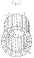
- Figure 2 shows the construction of figure 1 in a perspective view from the underside.
- Figure 3 shows diagrammatically a first step of the method according to the invention.
- Figure 4 shows diagrammatically a second step of the method according to the invention.
- Figure 5 shows in top view different shapes, not limitative, of pontoons to be applied.
- Figure 6 shows in top view, non limitative, circumferential shapes of constructions to be made.
- Figure 7 shows possible cross sections in the vertical plane, in particular of the lower portion, non limitative as well.
- Figure 8 shows in side view a step of the method.
- Figure 9 shows in the same way as figure 8 a further step of the method.
- Figure 10 shows in the same way as figures 8 and 9 still a further step of the method.
- Figure 11 shows in perspective a possible coupling of pontoons.
- Figure 12 shows in horizontal cross section a possible guiding of the pontoons upon guiding profiles of the construction.
- Figure 13 shows as larger scale than figure 1 a horizontal cross section through a part of the wall of the construction to be made.
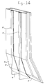
- Figure 14 is a perspective view of a part of the inner wall of the construction shown in figures 1 and figure 13.
- Figure 1 in general shows the construction to be manufactured with reference 1, which construction has to be placed upon the bottom of a body of water, not shown.
- Said construction has a polygonal circumference with an outer wall 2 and an inner wall 3.
- Said outer wall and inner wall respectively are, as clearly shown in figure 13, made as double wall with an inner plate 4 and an outer plate 5.
- Said outer wall and inner wall respectively are interconnected by transverse walls 6, which are performed as double walls as well and lie in planes, which are perpendicular to the inner and outer surface respectively. Said perpendicular position of course is not necessary.
- Said transverse wals 6 moreover need not to extend over the entire heigth. Feasible is to interrupt then locally.
- Said double walls are destined to be filled with concrete in the course of the manufacturing procedure.
- the degree of filling and the moment of filling depends on the need for buoyancy of ballasting respectively.
- the inner wall 3 has also been provided with hollow profiles 10 and 11 which need not to have a guiding function.
- said profiles 10 and 11 respectively extend vertically downwardly with the inwardly turned surface 12 extending vertically at the location of the inclined inner side 13 of the foot of the construction, so that below said foot an enlargement of the profile is formed in the form of a hollow casing 14.
- a suction conduit can be guided, not shown, or a pressure conduit, not shown, by means of which sand can be withdrawn from below the inner surface 15 of the inclined foot or by means of which filling substances, like sand or the like, can be introduced below the foot or by means of which hardening substances can be supplied or injected.
- the construction is surrounded by a ring of pontoons 16, which in top view have the shape of an equally sided trapezium the short parallel sides 17 of which having a length which corresponds to the plain surface 2 of the outer wall of the polygonal circumference of the construction.
- Said pontoons are rigidly coupled with each other in a manner shown in figure 11 and are guided upon the profiles shown in figure 12 by means of guiding means shown in more in detail in figure 12 as well.
- the pontoons can support the construction with or with no help of the own buoyancy of the construction.
- Said pontoons may have different shapes, a number of examples of which are shown in top view in figures 5a to 5e inclusive.
- Said shapes depend from the circumference of the construction to be made of which a number of examples are given in figures 6a to 6e inclusive, such as circular, polygonal, rectangular, oval, U-shaped.
- Figure 1 shows, there where a part of the wall is taken away, in vertical cross section the profile of the construction with an outer wall 2 performed as double wall and an inner wall 3 performed as double wall.
- the construction shown in figure 1 has in the upper portion parallel extending vertical inner and outer walls which in the lower portion merge into an inclined downwardly extending outer surface 21, a slightly less inclined inner surface 22 which further downwardly merges into an inclined surface 23, which forms a sharp lower edge 24 with the surface 21.
- Figure 7 shows possible cross sectional shapes of the lower portion each having a sharp lower edge 24a to 24e inclusive and with side walls in the upper portion, which extend vertically and parallel to each other, as shown in figures 7a to 7c incl., or extending inclined towards each other as shown in figures 7d and 7e respectively.
- figure 3 shows a first step.
- an annulose of pontoons such as the pontoons 16 of figure 1
- a horizontally made surface e.g. a shore area subjected to tides.
- Said pontoons are manufactured in the dry and during low tide one takes care that the bottom upon which the pontoons have to be placed in flattened, which ring of pontoons is placed during low tide and one takes care that during high tide the annulose of pontoons remains in place by ballasting, such as filling with water or placing weights upon it.
- the hollow foot shown in figure 4, has a shape such and a water displacement such that it has buoyancy.
- the lower portion can be assembled piece by piece on top of the ring of pontoons.
- the assembly then is brought towards deeper water, the pontoons are ballasted again until the lower portion floats, after which the pontoons are drawn away from below the floating lower portion. Said lower portion then one moves towards a place with quiet water, e.g. a habour, if it did not already arrive there or has been there.
- This lower portion then by ballasting is placed upon the bottom of the water and then the situation is generated which diagrammatically has been shown in figure 8, in which the lower portion 21 with the sharp lower edge 24 stands upon the bottom 26 of the body of water, preferably with part of the upper portion 27 extending above water.
- the ring of pontoons 16 then is placed around the upper portion and this upper portion is further built upwardly.
- pontoons will lift the construction and said construction then can be displaced with the aid of one or more tow boats 30.
- Said displacement takes place towards deeper water where the construction is lowered with the aid of cables with or without support by supplying water into the ballast spaces 31 (figure 1and 13). Said operations can, if desired, be repeated several times.
- FIG 11 shows a possible manner of coupling the pontoons 16. To this end they are provided with side surfaces turned towards each other and provided with flanges 32, 33 with coupling means, not shown, which could be formed by bolts which e.g. according to line 34 extend through holes of the flanges.
- connection may be insufficient for taking up the forces generated by wave movements in which case tension anchors 35 are applied, which with their outer ends are connected to the upper surface and lower surface (not shown) of the pontoons.
- each pontoon is guided upon hollow profiles 8 and 9 provided at the outer side of the construction.
- FIG 12 A possible cross sectional shape permitting guidance, is shown in figure 12.
- said figure 2 forms a piece of the outer wall plate of the construction and 17 is the surface of a trapezium shaped pontoon 16 turned towards it.
- the hollow profile such as 8 has, as shown in figure 12, such a horizontal cross section that guiding surfaces 37 and 38 are formed which extend perpendicular to the side faces of the hollow profiles 8.
- the guiding means 36 of figure 11 have profiles 39 and 40 connected thereto. Said profiles with the walls of the hollow profiles form a hollow space within which rolling guiding means can be provided.
- said profiles 39 and 40 have horizontal transverse surfaces at the outer ends, so that a closed chamber is formed.
- rolls such as balls, can be placed which then take care of a guidance with lower friction. If rolls are used which are enclosed in a fixed path, some friction of the rolls over at least one of the relatively movable surfaces cannot be exluded. Since the movements concerned are slow this need not to be an objection.
- rollers or wheels 40 having an axis of rotation which e.g. has been attached to profile 39, in which case the wheel or roller is rotatable free from profile 39 and in engagement with the surface 37 of the wall 38.
- the application 40 wheels requires shafts which extend perpendicular to each other, the forces then are taken up in two perpendicular horizontal directions and therewith the pontoon is guided upon the profile 8 such that displacements only are possible in vertical direction. vide figure 13.
Abstract
Claims (15)
- Procédé de fabrication d'une construction artificielle (1) posée sur le fond (26) d'un plan d'eau, telle qu'un îlot artificiel ou analogue, une colonne, un pilier, un port, etc., dans lequel une partie de la construction est fabriquée à distance de la destination finale dans une zone qui n'est pas exposée à l'influence des intempéries, qui sont désavantageuses pour le travail, et dans lequel ladite partie de la construction, une fois terminée, est déplacée dans un état de flottaison jusqu'à sa destination, et y est descendue sur le fond (26) du plan d'eau, ledit procédé comprenant :
d'abord la fabrication à sec de pontons,
la réalisation d'une plate-forme de travail à partir des pontons en reliant plusieurs pontons (16) dans un état de flottaison de sorte qu'une extrémité d'un ponton est reliée à l'extrémité opposée du ponton suivant, de sorte qu'ils définissent un espace ouvert à l'endroit auquel la partie inférieure de ladite construction artificielle (1) est fabriquée avec sa propre flottabilité, lequel espace ouvert entourée par l'anneau de pontons a une forme en vue de dessus qui est similaire à la forme du pourtour extérieur de ladite construction artificielle devant être fabriquée,
après avoir terminé ladite partie inférieure (20), ladite partie est mise en état de flottaison et déplacée vers une profondeur d'eau plus importante où elle est placée sur ledit fond (26) et, dans ledit état, une autre partie de ladite construction est ajoutée sur le dessus de la partie déjà fabriquée, utilisant ainsi la surface supérieure des pontons (16) accostant la partie déjà fabriquée,
après avoir terminé ladite autre partie de la construction, ladite construction est soulevée du fond (26) en utilisant la flottabilité des pontons (16) et/ou sa propre flottabilité et est déplacée davantage vers sa destination et, comme cela peut être le cas en une autre étape intermédiaire sur son trajet vers sa destination, elle est abaissée de nouveau jusqu'au fond de l'eau et reçoit une autre partie de la construction sur le dessus de la partie fabriquée et est de nouveau soulevée et ensuite abaissée à l'aide des pontons (16) jusqu'à ce que la destination soit atteinte, où la construction est descendue et les pontons sont retirés,
caractérisé en ce que
ladite partie inférieure de la construction est fabriquée sur la surface supérieure dudit anneau de pontons (16), laquelle partie inférieure comprend au moins une portion inférieure (21) de ladite construction (1), de sorte que le bord inférieur ou la base (24) de ladite construction (1) a un diamètre ou une distance entre des parties de bord opposées, respectivement, qui est supérieur(e) au diamètre du pourtour intérieur du cercle des pontons (16) ou supérieur(e) à la distance entre les bords intérieurs opposés des pontons, respectivement,
en ce que, après avoir terminé ladite partie inférieure, l'ensemble de pontons (16) et ladite partie inférieure sont mis en flottaison et déplacés vers une profondeur d'eau telle que ladite partie inférieure de la construction peut y flotter avec, entre sa base ou son bord inférieur (24) et le fond de l'eau (26), une distance supérieure à la hauteur des pontons (16),
en ce que les pontons (16) sont ensuite mis sur ballast et écartés du dessous de ladite partie de la construction, puis sont récupérés, après quoi ladite partie de la construction est placée sur le fond (26) du plan d'eau, et en ce qu'au moins une partie des pontons (16) utilisés à l'origine pour porter ladite partie inférieure (21) est placée contre la paroi extérieure de la construction et reliée à celle-ci d'une manière qui permet un mouvement vertical opportun contrôlable entre la construction et les pontons, lequel mouvement peut être empêché. - Procédé selon la revendication 1, caractérisé en ce que la liaison dans la direction verticale entre les pontons et la construction est réalisée à l'aide de câbles (19) dont une extrémité est reliée au pied (20) de la construction (1) et dont l'autre extrémité est reliée à un treuil (18) placé sur les pontons, et à l'aide desquels, depuis le côté des pontons (16), une force de tension contrôlable peut être appliquée câble par câble.
- Procédé selon la revendication 1 ou 2, caractérisé en ce que la mise en place de l'anneau de pontons (16) se fait sur un fond plat préparé (26) d'une zone d'eau qui est exposée aux marées et qu'elle se fait en un endroit qui permet le montage pendant la marée basse et la flottaison pendant la marée haute.
- Procédé selon la revendication 1 ou 3, caractérisé en ce que la mise en place de l'anneau de pontons (16) se fait sur un fond plat d'un espace qui peut être fermé par rapport à l'eau environnante, et duquel l'eau peut être retirée, tel qu'une zone de docks.
- Procédé selon la revendication 1 ou 2, caractérisé en ce que la mise en place de l'anneau de pontons (16) se fait en descendant lesdits pontons (16) au moyen de ballasts sur un fond préparé plat (26) d'un plan d'eau ayant un niveau pratiquement stable et une profondeur suffisante pour que les pontons y soient placés avec par dessus une partie de la construction, l'ensemble des pontons et de la partie étant rendus libres du fond par flottaison.
- Procédé selon l'une ou plusieures des revendications précédentes, caractérisé en ce que la fabrication de l'autre partie se fait en eau calme, dans un port ou une zone similaire protégée de la mer.
- Dispositif de fabrication d'une construction artificielle sur le fond d'un plan d'eau, telle qu'un îlot artificiel ou analogue, une colonne, un pilier, un port, etc. selon le procédé des revendications 1 à 6, ledit dispositif comprenant des pontons (16), chaque ayant une flottabilité contrôlable, qui sont reliés entre eux l'un derrière l'autre pour définir entre eux un espace ouvert dont la forme en vue de dessus correspond aux contours de la circonférence extérieure de la construction (1) devant être fabriquée, lequel anneau de pontons, pendant au moins une partie de la fabrication de ladite construction (1) entoure ladite construction, laquelle construction peut, au moins partiellement, être réalisée et être déplacée dans la direction verticale par rapport auxdits pontons, caractérisé en ce que les pontons (16) liés les uns aux autres forment une surface supérieure continue adaptée à recevoir la portion de base (24) de la construction (1) entre la circonférence intérieure et la circonférence extérieure dudit anneau de pontons (16) et en ce que les pontons (16) sont chacun munis de moyens à l'aide desquels un déplacement relatif vers le haut aussi bien que vers le bas peut être réalisé et à l'aide desquels les pontons peuvent être verrouillés par rapport à la construction, les pontons définissant une forme de circonférence intérieure ou diamètre, respectivement, qui s'adapte autour d'une partie supérieure de la construction à réaliser.
- Dispositif selon la revendication 7, caractérisé en ce que les pontons sont chacun munis de moyens de guidage (36) qui coopèrent avec des éléments de guidage (8,9) sur la construction (1) entourée par les pontons (16) et qui ne permettent qu'un mouvement relatif dans la direction verticale.
- Dispositif selon la revendication 7, caractérisé en ce que lesdits moyens comprennent des câbles (19) qui sont reliés par leurs extrémités libres au pied (24) de la construction et par leurs autres extrémités à un treuil (18), chaque ponton ayant au moins un treuil (18) avec un câble (19).
- Dispositif selon la revendication 7, caractérisé en ce que lesdits moyens comprennent un mécanisme de montée ayant une crémaillère ou analogue sur la face extérieure de la construction et un système de roues d'engrenage pouvant être entraînées et verrouillées sur ou dans chaque ponton.
- Dispositif selon la revendication 7, caractérisé en ce que lesdits moyens comprennent un mécanisme de montée du type comprenant des poutrelles de verrouillage et des cylindres de déplacement à l'aide desquels un déplacement relatif peut être effectué par paliers.
- Dispositif selon l'une ou plusieurs des revendications 7 à 11, caractérisé en ce que lesdits pontons (16) sont reliés les uns aux autres de façon détachable au moyen de brides (32,33) sur les faces latérales et en ce que des barres de tension (35) sont prévues au moins sur la surface supérieur, lesquelles pontent la liaison par brides.
- Dispositif selon l'une ou plusieurs des revendications 7 à 12, caractérisé en ce que chaque ponton (16) a une surface intérieure (17) tournée en direction de la construction (1) qui est complémentaire de la surface extérieure de la construction (1) ainsi que des faces latérales partant desdites surfaces intérieures qui forment avec la surface intérieure (17) un angle tel que l'accouplement des pontons (16) les uns aux autres suit le profil de la face extérieure de la construction.
- Construction fabriquée par le procédé selon les revendications 1 à 6 et au moyen du dispositif selon les revendications 7 à 13, telle qu'un îlot artificiel ou analogue, une colonne, un pilier, un port, etc., reposant sur le fond d'un plan d'eau, laquelle construction a une paroi creuse (2,3) fermée en bas et ouverte en haut et ayant un bord inférieur aigu (24), caractérisée en ce que chaque paroi intérieure (3) et chaque paroi extérieure (2) de la double paroi est elle-même une double paroi (4,5), lesdites doubles parois (2,3) étant, au moins dans la direction verticale, reliées entre elles localement par des doubles parois transversales (6) et en ce que les parois (4,5,6) des doubles parois (4,5) de la paroi extérieure (2), de la paroi intérieure (3) et de la paroi transversale (6) sont reliées entre elles par des ancrages (7), lesdites dernières doubles parois mentionnées munies d'ancrages (7) pouvant être remplie avec un matériau durcissant comme du béton, et en ce que la paroi extérieure de la construction a été munie de profils creux espacés (8) ayant des bords extérieurs de guidage (37) à l'intérieur desquels s'adaptent des moyens de guidage (36) des pontons (16), lesquels moyens de guidage (36) prennent prise derrière lesdits bords de guidage (37).
- Construction selon la revendication 14, caractérisée en ce que la paroi intérieure de la construction a été munie, en des emplacements séparés les uns des autres, de profils creux (10,11) s'étendant de haut en bas et qui sont ouverts de haut en bas.
Applications Claiming Priority (3)
| Application Number | Priority Date | Filing Date | Title |
|---|---|---|---|
| NL8902752A NL8902752A (nl) | 1989-11-07 | 1989-11-07 | Werkwijze voor het maken van een kunstmatige constructie op een waterbodem, zoals een kunstmatig eiland, inrichting voor het uitvoeren van de werkwijze volgens de uitvinding en constructie te vervaardigen met en verkregen door toepassing van werkwijze en inrichting volgens de uitvinding. |
| NL8902752 | 1989-11-07 | ||
| PCT/EP1990/001852 WO1991006714A1 (fr) | 1989-11-07 | 1990-11-05 | Procede et appareil de construction d'une ile artificielle et construction ainsi obtenue |
Publications (2)
| Publication Number | Publication Date |
|---|---|
| EP0500566A1 EP0500566A1 (fr) | 1992-09-02 |
| EP0500566B1 true EP0500566B1 (fr) | 1995-02-15 |
Family
ID=19855584
Family Applications (1)
| Application Number | Title | Priority Date | Filing Date |
|---|---|---|---|
| EP90915464A Expired - Lifetime EP0500566B1 (fr) | 1989-11-07 | 1990-11-05 | Procede et appareil de construction d'une ile artificielle et construction ainsi obtenue |
Country Status (15)
| Country | Link |
|---|---|
| US (1) | US5088858A (fr) |
| EP (1) | EP0500566B1 (fr) |
| JP (1) | JPH05503124A (fr) |
| KR (1) | KR0172616B1 (fr) |
| CN (1) | CN1040034C (fr) |
| AU (1) | AU6546490A (fr) |
| BR (1) | BR9007819A (fr) |
| CA (1) | CA2073190A1 (fr) |
| DE (1) | DE69017038T2 (fr) |
| ES (1) | ES2067765T3 (fr) |
| FI (1) | FI103737B (fr) |
| MC (1) | MC2212A1 (fr) |
| NL (1) | NL8902752A (fr) |
| NO (1) | NO308546B1 (fr) |
| WO (1) | WO1991006714A1 (fr) |
Families Citing this family (22)
| Publication number | Priority date | Publication date | Assignee | Title |
|---|---|---|---|---|
| US5493538A (en) * | 1994-11-14 | 1996-02-20 | Texas Instruments Incorporated | Minimum pulse width address transition detection circuit |
| GB9520806D0 (en) * | 1995-10-11 | 1995-12-13 | Kvaerner Earl & Wright | Buoyant platform |
| US5964550A (en) * | 1996-05-31 | 1999-10-12 | Seahorse Equipment Corporation | Minimal production platform for small deep water reserves |
| GB2330854B (en) | 1997-10-31 | 2002-04-17 | Ove Arup Partnership | Method of transporting and installing an offshore structure |
| US6213045B1 (en) * | 1998-08-27 | 2001-04-10 | Steve J. Gaber | Flotation system and method for off-shore platform and the like |
| US6374764B1 (en) * | 1998-11-06 | 2002-04-23 | Exxonmobil Upstream Research Company | Deck installation system for offshore structures |
| US6786679B2 (en) * | 1999-04-30 | 2004-09-07 | Abb Lummus Global, Inc. | Floating stability device for offshore platform |
| WO2001015970A1 (fr) * | 1999-08-27 | 2001-03-08 | Gaber Steve J | Systeme de flottaison et procede pour plate-forme offshore |
| RU2159320C1 (ru) * | 2000-05-15 | 2000-11-20 | Болдырев Владимир Санджиевич | Искусственный остров, опора искусственного острова и способ сооружения искусственного острова |
| CN1318703C (zh) * | 2003-10-31 | 2007-05-30 | 上海建工(集团)总公司 | 蜂窝半蜂窝状自浮套箱 |
| ATE557135T1 (de) * | 2004-07-16 | 2012-05-15 | Zakrytoe Aksionernoe Obschestvo Sneva Dorserviss | Verfahren zum bau eines flachen tunnels auf einem wasserbereichsboden und system zum vorübergehenden entwässern eines bodenbereiches |
| NL2003073C2 (nl) * | 2009-06-23 | 2010-12-27 | Ihc Holland Ie Bv | Inrichting en werkwijze voor het reduceren van geluid. |
| DE102010017220B4 (de) * | 2010-06-02 | 2015-05-07 | Gerd Dornberg | Vorrichtung zum Ausbilden eines geschützten Bereiches in einem Gewässer und Verfahren zum Aufbauen einer Vorrichtung |
| FR2970695B1 (fr) * | 2011-01-25 | 2013-01-04 | Dcns | Support flottant pour structure offshore de type eolienne |
| CN102979068B (zh) * | 2012-11-12 | 2013-12-18 | 天津大学 | 一种岛礁筑岛基础结构及其施工方法 |
| ES2563104B1 (es) * | 2013-06-05 | 2017-06-13 | Acciona Ingeniería, S.A. | Cajón para obras marítimas y procedimiento de montaje del mismo |
| US9062429B2 (en) * | 2013-08-13 | 2015-06-23 | James Lee | Shallow water jacket installation method |
| US10309071B2 (en) * | 2016-12-21 | 2019-06-04 | Exxonmobil Upstream Research Company | Floatable modular protective harbor structure and method of seasonal service extension of offshore vessels in ice-prone environments |
| US10065712B2 (en) * | 2016-12-21 | 2018-09-04 | Exxonmobil Upstream Research Company | Floating modular protective harbor structure and method of seasonal service extension of offshore vessels in ice-prone environments |
| KR101959691B1 (ko) * | 2018-10-24 | 2019-03-18 | 강병관 | 변단면 각관을 이용한 환형 가물막이 및 터파기 공사 가시설 구조물 그리고 시공 방법 |
| IL268914B (en) * | 2019-08-26 | 2022-08-01 | Israel Ports Dev & Assets Company Ltd | Marine construction and method for its construction |
| CN111502725B (zh) * | 2020-04-20 | 2021-09-28 | 中交第三航务工程局有限公司 | 一种海底掘进隧道的人工岛式中间井结构 |
Family Cites Families (14)
| Publication number | Priority date | Publication date | Assignee | Title |
|---|---|---|---|---|
| US1758606A (en) * | 1927-12-20 | 1930-05-13 | Jacobs Jacob | Marine foundation and method for making the same |
| US2050727A (en) * | 1934-09-19 | 1936-08-11 | Misz Oliver Benjamin | Caisson belt apparatus and method |
| FR1279746A (fr) * | 1961-01-25 | 1961-12-22 | Strabag Bau Ag | Ile artificielle et son procédé de fabrication |
| FR1497544A (fr) * | 1966-07-12 | 1967-10-13 | Entpr S Campenon Bernard | Procédé et installations de préfabrication de caissons en béton et caissons réalisés suivant ce procédé ou à l'aide de ces installations |
| US3740956A (en) * | 1970-11-12 | 1973-06-26 | Exxon Production Research Co | Portable retaining structure |
| GB1386053A (en) * | 1973-06-27 | 1975-03-05 | Lind Co Ltd Peter | Marine platforms of concrete |
| ES452097A1 (es) * | 1975-11-17 | 1977-10-16 | Liautaud Jean | Plataforma marina para operaciones de perforacion y simila- res. |
| US4118941A (en) * | 1977-05-16 | 1978-10-10 | Exxon Production Research Company | Stressed caisson retained island |
| US4094162A (en) * | 1977-06-21 | 1978-06-13 | Brown & Root, Inc. | Method for installing an offshore tower |
| US4293239A (en) * | 1979-04-02 | 1981-10-06 | Odeco Engineers Inc. | Method of erecting a very large diameter offshore column |
| GB2174648B (en) * | 1985-04-29 | 1988-10-12 | Heerema Engineering | Installation and removal vessel |
| US4711601A (en) * | 1985-06-03 | 1987-12-08 | Isaac Grosman | Method of installing offshore constructions |
| ES2003934A6 (es) * | 1985-11-17 | 1988-12-01 | Darya Paye Jetty Co Ltd | Procedimiento para la construccion de una estructura rigida sobre el fondo de una masa de agua |
| NL8800664A (nl) * | 1988-03-17 | 1989-10-16 | Darya Paye Jetty Co Ltd | Werkwijze en inrichting voor het vervaardigen van een waterbouwkundige constructie, zoals een pijler, steiger en dergelijke. |
-
1989
- 1989-11-07 NL NL8902752A patent/NL8902752A/nl not_active Application Discontinuation
-
1990
- 1990-11-05 AU AU65464/90A patent/AU6546490A/en not_active Abandoned
- 1990-11-05 MC MC901852D patent/MC2212A1/fr unknown
- 1990-11-05 JP JP2514424A patent/JPH05503124A/ja active Pending
- 1990-11-05 EP EP90915464A patent/EP0500566B1/fr not_active Expired - Lifetime
- 1990-11-05 DE DE69017038T patent/DE69017038T2/de not_active Expired - Fee Related
- 1990-11-05 WO PCT/EP1990/001852 patent/WO1991006714A1/fr active IP Right Grant
- 1990-11-05 ES ES90915464T patent/ES2067765T3/es not_active Expired - Lifetime
- 1990-11-05 KR KR1019920701069A patent/KR0172616B1/ko not_active IP Right Cessation
- 1990-11-05 CA CA002073190A patent/CA2073190A1/fr not_active Abandoned
- 1990-11-05 BR BR909007819A patent/BR9007819A/pt not_active IP Right Cessation
- 1990-11-07 CN CN90110049A patent/CN1040034C/zh not_active Expired - Fee Related
- 1990-11-07 US US07/610,360 patent/US5088858A/en not_active Expired - Fee Related
-
1992
- 1992-04-30 NO NO921693A patent/NO308546B1/no not_active IP Right Cessation
- 1992-05-06 FI FI922049A patent/FI103737B/fi active
Also Published As
| Publication number | Publication date |
|---|---|
| MC2212A1 (fr) | 1992-11-26 |
| CN1040034C (zh) | 1998-09-30 |
| CA2073190A1 (fr) | 1991-05-08 |
| KR0172616B1 (ko) | 1999-02-18 |
| NL8902752A (nl) | 1991-06-03 |
| FI103737B1 (fi) | 1999-08-31 |
| CN1052523A (zh) | 1991-06-26 |
| DE69017038T2 (de) | 1995-07-20 |
| KR920703933A (ko) | 1992-12-18 |
| WO1991006714A1 (fr) | 1991-05-16 |
| FI922049A (fi) | 1992-05-06 |
| NO921693D0 (no) | 1992-04-30 |
| FI103737B (fi) | 1999-08-31 |
| AU6546490A (en) | 1991-05-31 |
| NO921693L (no) | 1992-06-17 |
| EP0500566A1 (fr) | 1992-09-02 |
| US5088858A (en) | 1992-02-18 |
| NO308546B1 (no) | 2000-09-25 |
| DE69017038D1 (de) | 1995-03-23 |
| FI922049A0 (fi) | 1992-05-06 |
| BR9007819A (pt) | 1992-09-01 |
| ES2067765T3 (es) | 1995-04-01 |
| JPH05503124A (ja) | 1993-05-27 |
Similar Documents
| Publication | Publication Date | Title |
|---|---|---|
| EP0500566B1 (fr) | Procede et appareil de construction d'une ile artificielle et construction ainsi obtenue | |
| US3896628A (en) | Marine structures | |
| US3797256A (en) | Jack-up type offshore platform apparatus | |
| US4456404A (en) | Method and apparatus for positioning a working barge above a sea surface | |
| US3708985A (en) | Articulated marine platform | |
| US4618286A (en) | Composite platform for petroleum workings in polar seas | |
| US3751930A (en) | Articulated marine structure with prepositioned anchoring piles | |
| CA1119419A (fr) | Methode et dispositif de relevage de plate-forme a colonne de support unique avec base lestee | |
| US4266887A (en) | Self-elevating fixed platform | |
| US3852969A (en) | Offshore platform structures | |
| US4063426A (en) | Three column tower | |
| WO2000031349A1 (fr) | Plate-forme de travail artificielle autoelevatrice mobile pourvue d'une coque modulaire | |
| CA1204945A (fr) | Plate-forme fixe et mobile de forage en mer | |
| US2657540A (en) | Method of erecting and positioning marine structures | |
| JPS6113052B2 (fr) | ||
| IE45199B1 (en) | Method of fabrication of off-shore structures and off-shore structures made according to this method | |
| US2598329A (en) | Offshore drilling platform and method of constructing same | |
| RU2386755C1 (ru) | Способ возведения тоннеля мелкого заложения на дне акватории | |
| US4038830A (en) | Modular geometric offshore structures system | |
| CA1078631A (fr) | Plate-forme de production de petrole et methode d'assemblage et d'implantation sur fond marin | |
| US4193714A (en) | Method for erecting a deck on a marine structure | |
| CN109208624B (zh) | 一种海上升压站导管架调平施工工艺 | |
| CN109518674B (zh) | 一种人工岛节段、装配式人工岛及装配式人工岛的建造方法 | |
| US4388024A (en) | Support structure for offshore platforms | |
| US2935854A (en) | Offshore drilling platform |
Legal Events
| Date | Code | Title | Description |
|---|---|---|---|
| PUAI | Public reference made under article 153(3) epc to a published international application that has entered the european phase |
Free format text: ORIGINAL CODE: 0009012 |
|
| 17P | Request for examination filed |
Effective date: 19920428 |
|
| AK | Designated contracting states |
Kind code of ref document: A1 Designated state(s): DE ES FR GB IT NL |
|
| 17Q | First examination report despatched |
Effective date: 19931104 |
|
| GRAA | (expected) grant |
Free format text: ORIGINAL CODE: 0009210 |
|
| AK | Designated contracting states |
Kind code of ref document: B1 Designated state(s): DE ES FR GB IT NL |
|
| ET | Fr: translation filed | ||
| REF | Corresponds to: |
Ref document number: 69017038 Country of ref document: DE Date of ref document: 19950323 |
|
| ITF | It: translation for a ep patent filed |
Owner name: SOCIETA' ITALIANA BREVETTI S.P.A. |
|
| REG | Reference to a national code |
Ref country code: ES Ref legal event code: FG2A Ref document number: 2067765 Country of ref document: ES Kind code of ref document: T3 |
|
| PLBE | No opposition filed within time limit |
Free format text: ORIGINAL CODE: 0009261 |
|
| STAA | Information on the status of an ep patent application or granted ep patent |
Free format text: STATUS: NO OPPOSITION FILED WITHIN TIME LIMIT |
|
| 26N | No opposition filed | ||
| PGFP | Annual fee paid to national office [announced via postgrant information from national office to epo] |
Ref country code: GB Payment date: 20011106 Year of fee payment: 12 |
|
| PGFP | Annual fee paid to national office [announced via postgrant information from national office to epo] |
Ref country code: ES Payment date: 20011120 Year of fee payment: 12 |
|
| PGFP | Annual fee paid to national office [announced via postgrant information from national office to epo] |
Ref country code: FR Payment date: 20011122 Year of fee payment: 12 |
|
| PGFP | Annual fee paid to national office [announced via postgrant information from national office to epo] |
Ref country code: NL Payment date: 20011130 Year of fee payment: 12 |
|
| PGFP | Annual fee paid to national office [announced via postgrant information from national office to epo] |
Ref country code: DE Payment date: 20011211 Year of fee payment: 12 |
|
| REG | Reference to a national code |
Ref country code: GB Ref legal event code: IF02 |
|
| PG25 | Lapsed in a contracting state [announced via postgrant information from national office to epo] |
Ref country code: GB Free format text: LAPSE BECAUSE OF NON-PAYMENT OF DUE FEES Effective date: 20021105 |
|
| PG25 | Lapsed in a contracting state [announced via postgrant information from national office to epo] |
Ref country code: ES Free format text: LAPSE BECAUSE OF NON-PAYMENT OF DUE FEES Effective date: 20021106 |
|
| PG25 | Lapsed in a contracting state [announced via postgrant information from national office to epo] |
Ref country code: NL Free format text: LAPSE BECAUSE OF NON-PAYMENT OF DUE FEES Effective date: 20030601 |
|
| PG25 | Lapsed in a contracting state [announced via postgrant information from national office to epo] |
Ref country code: DE Free format text: LAPSE BECAUSE OF NON-PAYMENT OF DUE FEES Effective date: 20030603 |
|
| GBPC | Gb: european patent ceased through non-payment of renewal fee | ||
| PG25 | Lapsed in a contracting state [announced via postgrant information from national office to epo] |
Ref country code: FR Free format text: LAPSE BECAUSE OF NON-PAYMENT OF DUE FEES Effective date: 20030731 |
|
| NLV4 | Nl: lapsed or anulled due to non-payment of the annual fee |
Effective date: 20030601 |
|
| REG | Reference to a national code |
Ref country code: FR Ref legal event code: ST |
|
| REG | Reference to a national code |
Ref country code: ES Ref legal event code: FD2A Effective date: 20031213 |
|
| PG25 | Lapsed in a contracting state [announced via postgrant information from national office to epo] |
Ref country code: IT Free format text: LAPSE BECAUSE OF NON-PAYMENT OF DUE FEES;WARNING: LAPSES OF ITALIAN PATENTS WITH EFFECTIVE DATE BEFORE 2007 MAY HAVE OCCURRED AT ANY TIME BEFORE 2007. THE CORRECT EFFECTIVE DATE MAY BE DIFFERENT FROM THE ONE RECORDED. Effective date: 20051105 |