EP0500566B1 - Method and apparatus for constructing an artificial island and construction thus obtained - Google Patents
Method and apparatus for constructing an artificial island and construction thus obtained Download PDFInfo
- Publication number
- EP0500566B1 EP0500566B1 EP90915464A EP90915464A EP0500566B1 EP 0500566 B1 EP0500566 B1 EP 0500566B1 EP 90915464 A EP90915464 A EP 90915464A EP 90915464 A EP90915464 A EP 90915464A EP 0500566 B1 EP0500566 B1 EP 0500566B1
- Authority
- EP
- European Patent Office
- Prior art keywords
- pontoons
- construction
- water
- wall
- ring
- Prior art date
- Legal status (The legal status is an assumption and is not a legal conclusion. Google has not performed a legal analysis and makes no representation as to the accuracy of the status listed.)
- Expired - Lifetime
Links
- 238000000034 method Methods 0.000 title claims abstract description 26
- 238000010276 construction Methods 0.000 title claims description 165
- XLYOFNOQVPJJNP-UHFFFAOYSA-N water Substances O XLYOFNOQVPJJNP-UHFFFAOYSA-N 0.000 claims abstract description 62
- 238000004519 manufacturing process Methods 0.000 claims abstract description 29
- 238000007667 floating Methods 0.000 claims abstract description 16
- 238000006073 displacement reaction Methods 0.000 claims description 10
- 230000009194 climbing Effects 0.000 claims description 7
- 230000008878 coupling Effects 0.000 claims description 6
- 238000010168 coupling process Methods 0.000 claims description 6
- 238000005859 coupling reaction Methods 0.000 claims description 6
- 230000000284 resting effect Effects 0.000 claims description 3
- 239000000463 material Substances 0.000 claims description 2
- 230000000295 complement effect Effects 0.000 claims 1
- 241000826860 Trapezium Species 0.000 description 5
- 239000004576 sand Substances 0.000 description 5
- 239000000126 substance Substances 0.000 description 5
- 230000002787 reinforcement Effects 0.000 description 3
- 238000005553 drilling Methods 0.000 description 2
- 238000005452 bending Methods 0.000 description 1
- 239000011796 hollow space material Substances 0.000 description 1
- 238000009434 installation Methods 0.000 description 1
- 238000011835 investigation Methods 0.000 description 1
- 238000005086 pumping Methods 0.000 description 1
- 230000003014 reinforcing effect Effects 0.000 description 1
- 238000005096 rolling process Methods 0.000 description 1
Images


Classifications
-
- E—FIXED CONSTRUCTIONS
- E02—HYDRAULIC ENGINEERING; FOUNDATIONS; SOIL SHIFTING
- E02B—HYDRAULIC ENGINEERING
- E02B17/00—Artificial islands mounted on piles or like supports, e.g. platforms on raisable legs or offshore constructions; Construction methods therefor
- E02B17/02—Artificial islands mounted on piles or like supports, e.g. platforms on raisable legs or offshore constructions; Construction methods therefor placed by lowering the supporting construction to the bottom, e.g. with subsequent fixing thereto
- E02B17/027—Artificial islands mounted on piles or like supports, e.g. platforms on raisable legs or offshore constructions; Construction methods therefor placed by lowering the supporting construction to the bottom, e.g. with subsequent fixing thereto steel structures
-
- E—FIXED CONSTRUCTIONS
- E02—HYDRAULIC ENGINEERING; FOUNDATIONS; SOIL SHIFTING
- E02B—HYDRAULIC ENGINEERING
- E02B17/00—Artificial islands mounted on piles or like supports, e.g. platforms on raisable legs or offshore constructions; Construction methods therefor
- E02B17/0017—Means for protecting offshore constructions
- E02B17/0021—Means for protecting offshore constructions against ice-loads
-
- E—FIXED CONSTRUCTIONS
- E02—HYDRAULIC ENGINEERING; FOUNDATIONS; SOIL SHIFTING
- E02D—FOUNDATIONS; EXCAVATIONS; EMBANKMENTS; UNDERGROUND OR UNDERWATER STRUCTURES
- E02D23/00—Caissons; Construction or placing of caissons
- E02D23/02—Caissons able to be floated on water and to be lowered into water in situ
-
- E—FIXED CONSTRUCTIONS
- E02—HYDRAULIC ENGINEERING; FOUNDATIONS; SOIL SHIFTING
- E02B—HYDRAULIC ENGINEERING
- E02B17/00—Artificial islands mounted on piles or like supports, e.g. platforms on raisable legs or offshore constructions; Construction methods therefor
- E02B2017/0039—Methods for placing the offshore structure
Definitions
- the invention in the first place relates to a method of manufacturing an artificial construction on the bottom of a body of water, such as an artificial island or the like, a column, a pile, a harbour, etc., in which a part of the construction is manufactured at a distance from the final destination in an area which is free from weather conditions, which are disadvantageous for the work, and in which said part of the construction, after completion, is moved in floating condition towards its destination and there lowered upon the bottom of the body of water, said method comprising: first the manufacturing in the dry of pontoons, forming a working platform from the pontoons by interconnecting a number of pontoons in floatable condition such that one end of a pontoon is connected to the opposite end of the next pontoon such that they define an open space at the location of which the lower part of the said artificial construction is made with own buoyancy, which open space, surrounded by the ring of pontoons, has a shape in plan view which is similar in form with the outer circumferential shape of the said artificial
- artificial construction covers arrangements, such as drilling platforms, platforms capable to withstand ice bergs, platforms for investigation or for military purposes.
- Purpose of the invention is to provide a method which is more simple and accordingly more cheap and more flexible with respect to the area where the work has to be done.
- the said lower part of the construction is made on the upper surface of said ring of pontoons which lower part comprises at least the lower portion of said construction, such that the lower edge or base of said construction has a diameter or distance between opposite edge parts respectively, which is larger than the diameter of the inner edge of the circle of pontoons or larger than the distance between opposite inner edges of the pontoons respectively, and that after having completed said lower part the assembly of pontoons and said lower part is floated and moved towards a water depth such that the said lower portion of the construction can float in it with between its lower edge or base and the water bottom a distance which is larger than the height of the pontoons, that thereafter the pontoons are ballasted and moved away from below said part of the construction and subsequently are recovered after which said part of the construction is placed upon the bottom of the body of water and that at least part of the pontoons originally used for carrying said lower portion are placed against the outer wall of the construction and connected therewith in a manner which allows a controllable relevant vertical movement
- the construction starts with the manufacturing of the lower portion of the construction on the top of the ring of pontoons between the side boundaries of said pontoons.
- a ring of pontoons Even if rigidly interconnected, is not a stable platform from which the manufacturing of the construction can be done.
- said pontoons in the beginning of the operation are supported by a rigid surface called the working surface.
- the working surface On the top of said pontoons which due to being supported by the working surface are not subjected to water movements in case water is present in said first stage, the lower part of the construction to be made is manufactured.
- Said lower part resting by its own weight on the pontoons gives sufficient rigidity to the sequence of pontoons such that after being brought in a buoyant condition pontoons and on top of them the lower part of the construction can be floated away to an area of deeper water because the sequence of pontoons now obtains additional rigidity from the already made part of the construction resting upon it.
- This can be a shore area, subjected to tides, in which case one places the pontoons during low tide and are floated when time comes at high tide together with the already manufactured portion of the construction placed upon it.
- the assembly of pontoons and lower portion standing upon it is brought in floating condition or in floating condition respectively towards deeper water, where the pontoons are removed by ballasting and subsequently the floating lower portion, as far as still necessary, is moved towards a place in quiet water where this portion is placed upon the bottom and one continues the assembly of the construction.
- the removed portion then can again be placed around the already manufactured portion and can be coupled therewith and due to this function as working platform.
- the construction can be towed towards the location of destination and there by ballasting and with the aid of means controlling the lowering movement lowered upon the bottom of the sea and subsequently anchored thereto.
- the present invention in particular is destined for very large constructions.
- a simple control of the relative position can be achieved according to the invention in that the coupling in the vertical sense is obtained between pontoons and construction by means of cables, one end of which being connected to the foot of the construction and the other end to winches which are placed upon the pontoons and by means of which from the pontoons cable by cable a controllable tension can be performed.
- An artificial construction of the type meant here and of the dimensions which can be large, may have any desirable circumferential shape, seen in the horizontal plane. This can be a circular circumference, a polygonal circumference, a rectangular circumference, an oval circumference or even the circumference of a harbour having two jetties and an interconnecting portion (U-shape).
- the invention also relates to a device for manufacturing said artificial construction, said device comprising pontoons, each with controllable buoyancy, which are interconnected with each other one behind the other to define between them an open space the shape of which in plan view corresponds to the contours of the outer circumference of the constructions to be made, which ring of pontoons during at least part of the manufacturing of said construction surround said construction which construction at least partly can be performed and be displaced in vertical direction with respect to said pontoons.
- a method is known as well as an apparatus for manufacturing a column upon a bottom of a body of water by interconnecting two pontoons rigidly to form a working platform which is fully equipped for manufacturing said column, which pontoons in the interconnected condition define an opening or recess above which the column is manufactured and through which the manufactured part of the column can be lowered downwardly upon the water bottom.
- Said known method also starts by rigidly supporting the platform at the shore on the water bottom and by using the buoyancy of the platform to move the already manufactured part of the column to deeper water where said part is lowered through the recess or opening until it rests on the water bottom and then forms an anchor for the platform from which further manufacturing takes place.
- This platform never moves below water level and cannot be because it carries workshops etc. for performing the construction.
- the two pontoons which form the device define the opening substantially in the centre of the platform.
- the interconnected pontoons form a continuous top surface adapted to receive the base portion of the construction between the inner circumference and the outer circumference of said ring of pontoons and that the pontoons each are provided with means by means of which a relative displacement upwardly as well as downwardly can be performed and by means of which the pontoons can be locked with respect to the construction, which pontoons define an inner circumferential shape or diameter respectively, which fits around a higher part of the construction to be made.
- a circular ring is made from pontoons and said pontoons then have a curved inner surface, side faces in radial planes and an outer surface which can be curved but need not to be.
- the most suitable form of the pontoons is the one of an equal sided trapezium of which the small one of the two parallel sides lies against a side surface of the polygonal circumference of which the large parallel side forms the outer surface.
- the construction to be manufactured may have any circumferential shape, it of course of feasible, that the pontoons have other shapes, which in top view may be square, triangular, unequally sided trapezium, rectangular trapezium, with or without straight or curved surfaces.
- each of the pontoons have been provided with guiding means, which cooperate with guiding members on the construction and closed by the pontoons and which only allow relative movement in vertical direction.
- Each of the pontoons moreover can be provided with means by means of which a relative displacement upwardly as well as downwardly can be performed and by means of which the pontoons can be locked with respect to the construction.
- said means comprise cables, which with their free end are connected to the foot of the construction and with their other end to a winch and that each pontoon has at least one winch with cable.
- said means comprise a climbing mechanism having a toothed rod or the like at the outer side of the construction and a drivable and lockable gear wheel mechanism upon or in each pontoon respectively, or that said means comprise a climbing mechanism of the type having locking beams and displacement cylinders by means of which a stepwise relative displacement can be performed.
- the climbing mechanism mentioned above with toothed rod and gear wheels which preferably are driven by hydraulic motors, or the climbing mechanism comprising cylinders and locking beams is known in itself with artificial islands of the "jack-up" type, comprising a pontoon and at least three legs, which with the aid of said climbing mechanism can be moved in vertical direction with respect to the pontoon and can be locked.
- Said means can be applied with the present invention, but are relatively expensive as compared to winches with cables.
- the pontoons in coupled condition have to form a rigid entity. To this end they are mutually interconnected by means of flanges at the end faces or side faces and by means of tension anchors at the location of at least the top surface, which anchors bridge the flange connection.
- a preferred embodiment of such a construction of the type having a hollow wall closed at the bottom and open at the top and having a sharp lower edge is characterized in that the inner wall of the construction has been provided at spaced apart places with hollow profiles extending from top to bottom and open from top to bottom.
- the double walls eventually with the filling of hardening material provide strength, rigidity and stability and the properly guided stable guidance of each pontoon upon the outer wall without affecting the construction in case the pontoons are subjected to strong wave forces.
- Preferably two hollow profiles are provided for each pontoon to obtain the best possible guidance which prevents jamming.
- the hollow profiles not only guide but also form a reinforcement rib upon the outer surface of the respective surface of the construction.
- the construction is made from plate which provide tight walls.
- profiles at the outer side can at a suitable moment be provided with a reinforcement and/or filling with concrete.
- the inner wall of the construction with spaced apart hollow profiles as well which extend from top to bottom and are open from top to bottom. These are continuously open profiles which apart from the function of reinforcing the inner wall may be used for other purposes.
- the construction has a diameter of e.g. 100 meters then it will be clear, that the inner and outer wall are at a mutual distance in the magnitude of 15 to 20 meters and that each inner wall or outer wall respectively, made as double wall, has a thickness of 1.5 to 2 meters.
- the construction does have a sharp lower edge and upon placing it upon the bottom of the body of water will partly penetrate into said bottom. It, however, will be necessary to take care that the axis of the construction is correctly vertical. This may involve the need of treating the bottom but since this has to take place at large depth this hardly can be done previously.
- hollow profiles may still be used for performing drillings and if necessary for extending through it a riser or production conduit. This of course depends from the destination of the construction.
- transverse beams which bridge the space between opposite walls, in particular the inner walls and accordingly may form a working platform or support in the centre of which a construction crane may be provided.
- Figure 1 is a diagrammatic view in perspective of a construction obtained with the method according to the invention and to be manufactured with the apparatus according to the invention, in which for clearness sake part of the wall is taken away.
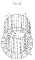
- Figure 2 shows the construction of figure 1 in a perspective view from the underside.
- Figure 3 shows diagrammatically a first step of the method according to the invention.
- Figure 4 shows diagrammatically a second step of the method according to the invention.
- Figure 5 shows in top view different shapes, not limitative, of pontoons to be applied.
- Figure 6 shows in top view, non limitative, circumferential shapes of constructions to be made.
- Figure 7 shows possible cross sections in the vertical plane, in particular of the lower portion, non limitative as well.
- Figure 8 shows in side view a step of the method.
- Figure 9 shows in the same way as figure 8 a further step of the method.
- Figure 10 shows in the same way as figures 8 and 9 still a further step of the method.
- Figure 11 shows in perspective a possible coupling of pontoons.
- Figure 12 shows in horizontal cross section a possible guiding of the pontoons upon guiding profiles of the construction.
- Figure 13 shows as larger scale than figure 1 a horizontal cross section through a part of the wall of the construction to be made.
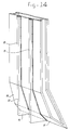
- Figure 14 is a perspective view of a part of the inner wall of the construction shown in figures 1 and figure 13.
- Figure 1 in general shows the construction to be manufactured with reference 1, which construction has to be placed upon the bottom of a body of water, not shown.
- Said construction has a polygonal circumference with an outer wall 2 and an inner wall 3.
- Said outer wall and inner wall respectively are, as clearly shown in figure 13, made as double wall with an inner plate 4 and an outer plate 5.
- Said outer wall and inner wall respectively are interconnected by transverse walls 6, which are performed as double walls as well and lie in planes, which are perpendicular to the inner and outer surface respectively. Said perpendicular position of course is not necessary.
- Said transverse wals 6 moreover need not to extend over the entire heigth. Feasible is to interrupt then locally.
- Said double walls are destined to be filled with concrete in the course of the manufacturing procedure.
- the degree of filling and the moment of filling depends on the need for buoyancy of ballasting respectively.
- the inner wall 3 has also been provided with hollow profiles 10 and 11 which need not to have a guiding function.
- said profiles 10 and 11 respectively extend vertically downwardly with the inwardly turned surface 12 extending vertically at the location of the inclined inner side 13 of the foot of the construction, so that below said foot an enlargement of the profile is formed in the form of a hollow casing 14.
- a suction conduit can be guided, not shown, or a pressure conduit, not shown, by means of which sand can be withdrawn from below the inner surface 15 of the inclined foot or by means of which filling substances, like sand or the like, can be introduced below the foot or by means of which hardening substances can be supplied or injected.
- the construction is surrounded by a ring of pontoons 16, which in top view have the shape of an equally sided trapezium the short parallel sides 17 of which having a length which corresponds to the plain surface 2 of the outer wall of the polygonal circumference of the construction.
- Said pontoons are rigidly coupled with each other in a manner shown in figure 11 and are guided upon the profiles shown in figure 12 by means of guiding means shown in more in detail in figure 12 as well.
- the pontoons can support the construction with or with no help of the own buoyancy of the construction.
- Said pontoons may have different shapes, a number of examples of which are shown in top view in figures 5a to 5e inclusive.
- Said shapes depend from the circumference of the construction to be made of which a number of examples are given in figures 6a to 6e inclusive, such as circular, polygonal, rectangular, oval, U-shaped.
- Figure 1 shows, there where a part of the wall is taken away, in vertical cross section the profile of the construction with an outer wall 2 performed as double wall and an inner wall 3 performed as double wall.
- the construction shown in figure 1 has in the upper portion parallel extending vertical inner and outer walls which in the lower portion merge into an inclined downwardly extending outer surface 21, a slightly less inclined inner surface 22 which further downwardly merges into an inclined surface 23, which forms a sharp lower edge 24 with the surface 21.
- Figure 7 shows possible cross sectional shapes of the lower portion each having a sharp lower edge 24a to 24e inclusive and with side walls in the upper portion, which extend vertically and parallel to each other, as shown in figures 7a to 7c incl., or extending inclined towards each other as shown in figures 7d and 7e respectively.
- figure 3 shows a first step.
- an annulose of pontoons such as the pontoons 16 of figure 1
- a horizontally made surface e.g. a shore area subjected to tides.
- Said pontoons are manufactured in the dry and during low tide one takes care that the bottom upon which the pontoons have to be placed in flattened, which ring of pontoons is placed during low tide and one takes care that during high tide the annulose of pontoons remains in place by ballasting, such as filling with water or placing weights upon it.
- the hollow foot shown in figure 4, has a shape such and a water displacement such that it has buoyancy.
- the lower portion can be assembled piece by piece on top of the ring of pontoons.
- the assembly then is brought towards deeper water, the pontoons are ballasted again until the lower portion floats, after which the pontoons are drawn away from below the floating lower portion. Said lower portion then one moves towards a place with quiet water, e.g. a habour, if it did not already arrive there or has been there.
- This lower portion then by ballasting is placed upon the bottom of the water and then the situation is generated which diagrammatically has been shown in figure 8, in which the lower portion 21 with the sharp lower edge 24 stands upon the bottom 26 of the body of water, preferably with part of the upper portion 27 extending above water.
- the ring of pontoons 16 then is placed around the upper portion and this upper portion is further built upwardly.
- pontoons will lift the construction and said construction then can be displaced with the aid of one or more tow boats 30.
- Said displacement takes place towards deeper water where the construction is lowered with the aid of cables with or without support by supplying water into the ballast spaces 31 (figure 1and 13). Said operations can, if desired, be repeated several times.
- FIG 11 shows a possible manner of coupling the pontoons 16. To this end they are provided with side surfaces turned towards each other and provided with flanges 32, 33 with coupling means, not shown, which could be formed by bolts which e.g. according to line 34 extend through holes of the flanges.
- connection may be insufficient for taking up the forces generated by wave movements in which case tension anchors 35 are applied, which with their outer ends are connected to the upper surface and lower surface (not shown) of the pontoons.
- each pontoon is guided upon hollow profiles 8 and 9 provided at the outer side of the construction.
- FIG 12 A possible cross sectional shape permitting guidance, is shown in figure 12.
- said figure 2 forms a piece of the outer wall plate of the construction and 17 is the surface of a trapezium shaped pontoon 16 turned towards it.
- the hollow profile such as 8 has, as shown in figure 12, such a horizontal cross section that guiding surfaces 37 and 38 are formed which extend perpendicular to the side faces of the hollow profiles 8.
- the guiding means 36 of figure 11 have profiles 39 and 40 connected thereto. Said profiles with the walls of the hollow profiles form a hollow space within which rolling guiding means can be provided.
- said profiles 39 and 40 have horizontal transverse surfaces at the outer ends, so that a closed chamber is formed.
- rolls such as balls, can be placed which then take care of a guidance with lower friction. If rolls are used which are enclosed in a fixed path, some friction of the rolls over at least one of the relatively movable surfaces cannot be exluded. Since the movements concerned are slow this need not to be an objection.
- rollers or wheels 40 having an axis of rotation which e.g. has been attached to profile 39, in which case the wheel or roller is rotatable free from profile 39 and in engagement with the surface 37 of the wall 38.
- the application 40 wheels requires shafts which extend perpendicular to each other, the forces then are taken up in two perpendicular horizontal directions and therewith the pontoon is guided upon the profile 8 such that displacements only are possible in vertical direction. vide figure 13.
Abstract
Description
- The invention in the first place relates to a method of manufacturing an artificial construction on the bottom of a body of water, such as an artificial island or the like, a column, a pile, a harbour, etc., in which a part of the construction is manufactured at a distance from the final destination in an area which is free from weather conditions, which are disadvantageous for the work, and in which said part of the construction, after completion, is moved in floating condition towards its destination and there lowered upon the bottom of the body of water, said method comprising:
first the manufacturing in the dry of pontoons,
forming a working platform from the pontoons by interconnecting a number of pontoons in floatable condition such that one end of a pontoon is connected to the opposite end of the next pontoon such that they define an open space at the location of which the lower part of the said artificial construction is made with own buoyancy, which open space, surrounded by the ring of pontoons, has a shape in plan view which is similar in form with the outer circumferential shape of the said artificial construction to be made,
that after having completed said lower part said part is brought into floating condition and moved towards a larger water depth where it is placed upon the said bottom and in said condition a further portion of the said constructions is added on top of the already made part, thereby making use of the top surface of the pontoons alongside the already made part,
that after completion of said further portion of the construction said construction is lifted from the bottom by making use of the buoyancy of the pontoons and/or its own buoyancy and is moved further towards its destination and, as the case may be at a further intermediate step on its travel towards its destination is lowered again on the water bottom and provided with a further part of the construction on top of the manufactured part and is again lifted and subsequently lowered with the aid of the pontoons until the destination is reached, the construction is lowered and the pontoons are removed. - The term "artificial construction" covers arrangements, such as drilling platforms, platforms capable to withstand ice bergs, platforms for investigation or for military purposes.
- A method of this type is known from NL-A-8800664 (=EP-A-0 333287) but for relatively small artificial constructions, such as a column or a pile.
- For large constructions it is known that one did manufacture in a Norwegian harbour a very large artificial island construction from concrete, towed in floating condition towards the location in the so-called Ecofisk area of the Northsea and lowered it there by ballasting upon the bottom of the sea and anchored it.
- It is evident, that manufacturing and in particular transportation of the entire island is cumbersome and expensive affair. Moreover, one usually is bound to a place of manufacturing, which place of manufacturing, in view of the often large height of such a construction, has to have a dock, within which at least the lower portion can be manufactured and which allows, by sufficient depth, to bring the entire construction in floating condition after completion.
- With the method known from NL-A-8800664 manufacturing of the artificial construction such as a column takes place from the top of the pontoon, which is fully equipped as working platform. Large constructions cannot be made in this way because the dimensions of the pontoon would become impossibly large not to speak about the costs.
- Purpose of the invention is to provide a method which is more simple and accordingly more cheap and more flexible with respect to the area where the work has to be done.
- This purpose is achieved in that the said lower part of the construction is made on the upper surface of said ring of pontoons which lower part comprises at least the lower portion of said construction, such that the lower edge or base of said construction has a diameter or distance between opposite edge parts respectively, which is larger than the diameter of the inner edge of the circle of pontoons or larger than the distance between opposite inner edges of the pontoons respectively,
and that after having completed said lower part the assembly of pontoons and said lower part is floated and moved towards a water depth such that the said lower portion of the construction can float in it with between its lower edge or base and the water bottom a distance which is larger than the height of the pontoons,
that thereafter the pontoons are ballasted and moved away from below said part of the construction and subsequently are recovered after which said part of the construction is placed upon the bottom of the body of water and that at least part of the pontoons originally used for carrying said lower portion are placed against the outer wall of the construction and connected therewith in a manner which allows a controllable relevant vertical movement between construction and pontoons, which movement can be blocked. - Accordingly the construction starts with the manufacturing of the lower portion of the construction on the top of the ring of pontoons between the side boundaries of said pontoons. With large dimensions such a ring of pontoons, even if rigidly interconnected, is not a stable platform from which the manufacturing of the construction can be done. In floating condition such a ring of pontoons would be continuously bent by the slightest waves and accordingly not be suitable as working surface. Thus according to the invention said pontoons in the beginning of the operation are supported by a rigid surface called the working surface. On the top of said pontoons which due to being supported by the working surface are not subjected to water movements in case water is present in said first stage, the lower part of the construction to be made is manufactured. Said lower part resting by its own weight on the pontoons gives sufficient rigidity to the sequence of pontoons such that after being brought in a buoyant condition pontoons and on top of them the lower part of the construction can be floated away to an area of deeper water because the sequence of pontoons now obtains additional rigidity from the already made part of the construction resting upon it.
- In deeper water the assembly of pontoons and lower part of the construction are lowered by reducing the buoyancy of the pontoons and the pontoons are removed and at least partly but preferably with all of them replaced around the construction and connected therewith to provide for access for further manufacturing of the construction and to provide additional controllable buoyancy for lifting the construction, moving it and lowering it in more deep water.
- This means accordingly that one also can operate with all pontoons which in that case accordingly are again placed around the constructions, but as well that one provides the construction at the outer side with a ring guided upon it to which the pontoons can be connected or along which the pontoons can be moved according to the circumference of the ring, so that one only uses a part of the pontoons as working platform.
- Herewith one in the first place achieves that the lower part or foot portion of the construction is manufactured in shallow water or in the dry on top of a series of pontoons which rest upon a horizontal surface or a surface which is made horizontal.
- This can be a shore area, subjected to tides, in which case one places the pontoons during low tide and are floated when time comes at high tide together with the already manufactured portion of the construction placed upon it.
- Of course one can do this in dock as well, so that the work takes place completely in the dry, which dock lateron is filled with water. In that case the dock needs, however, not to have an exceptional water depth.
- It is possible as well, in particular if the tide differences are small and one can speak about a practically constant level, to work in shallow water in which case the pontoons are placed upon a horizontal or horizontally made bottom by ballasting the pontoons, after which again on top of the pontoons the lower portion of the construction is placed, be it in its entirety or in part.
- After the manufacturing of said lower portion the assembly of pontoons and lower portion standing upon it, is brought in floating condition or in floating condition respectively towards deeper water, where the pontoons are removed by ballasting and subsequently the floating lower portion, as far as still necessary, is moved towards a place in quiet water where this portion is placed upon the bottom and one continues the assembly of the construction. The removed portion then can again be placed around the already manufactured portion and can be coupled therewith and due to this function as working platform.
- In case the construction is completed at the last mentioned place, at least as far as reaching the desired height is concerned, then with the aid of the buoyancy of said construction and for the buoyancy of the pontoons coupled therewith, the construction can be towed towards the location of destination and there by ballasting and with the aid of means controlling the lowering movement lowered upon the bottom of the sea and subsequently anchored thereto.
- As soon as the pontoons no longer are necessary, they are removed and one can complete the construction for the purpose it is meant for. If e.g. an artificial island is concerned filling, at least partly, with sand or the like, will take place, whilst moreover on top of it or inside the installation can be placed for which the constructions is destined.
- The present invention in particular is destined for very large constructions. One should think therewith of diameters of 100 to 200 meters and heights of 100 to 200 meters more. Said dimensions, however, are in no way limitative, smaller or larger is possible as well.
- If during manufacturing of said further portion of the construction one, e.g. by the height and the local circumstance with respect to water depths, cannot go that far that the construction is completely completed and accordingly one only can complete it partly, then according to the invention one subsequently with the aid of the pontoons can move the construction towards deeper water, where the already manufacturing portion is lowered upon the lower bottom of water and a next portion of the construction is made on top of the already manufactured portion. Said steps of floating, displacing, lowering and further completing then are repeated as often as necessary until the construction can move towards the location of destination or can be completed there respectively.
- Most shores are bordered by an area having a width of tenths of kilometres with gradually increasing depths, due to which at many places one has the possibility to complete the construction, such as the artificial island step by step in height. The pontoons then are rigidly interconnected and form a ring and the coupling of the pontoons with the construction takes place such, that only a controllable relative vertical movement between construction and pontoons may be possible. With other words the pontoons are guided upon the construction for vertical guidance, which construction to this end has been provided with guiding members. Accordingly the pontoons only can move in a vertical direction with respect to the construction and the reverse. Movements away from each other or towards each other are not possible.
- A simple control of the relative position can be achieved according to the invention in that the coupling in the vertical sense is obtained between pontoons and construction by means of cables, one end of which being connected to the foot of the construction and the other end to winches which are placed upon the pontoons and by means of which from the pontoons cable by cable a controllable tension can be performed.
- Accordingly with the invention one has the possibility to manufacture on a ring of rigidly interconnected by disconnectable pontoons a first portion of a large construction to be placed in the sea. Subsequently, after placing of said construction on a working bottom, accordingly after removal of the pontoons, said construction by means of the pontoons now placed around it, which pontoons serve as working platform, is completed, is displaced with the pontoons towards deeper water and, if this is done in steps, the construction is also completed step by step in height, and finally the construction with the aid of its own buoyancy and the buoyancy of the pontoons is moved towards the location of destination. There the pontoons finally once will be removed for repeated use.
- An artificial construction of the type meant here and of the dimensions which can be large, may have any desirable circumferential shape, seen in the horizontal plane. This can be a circular circumference, a polygonal circumference, a rectangular circumference, an oval circumference or even the circumference of a harbour having two jetties and an interconnecting portion (U-shape).
- The invention also relates to a device for manufacturing said artificial construction, said device comprising pontoons, each with controllable buoyancy, which are interconnected with each other one behind the other to define between them an open space the shape of which in plan view corresponds to the contours of the outer circumference of the constructions to be made, which ring of pontoons during at least part of the manufacturing of said construction surround said construction which construction at least partly can be performed and be displaced in vertical direction with respect to said pontoons.
- From NL-A-8800664 a method is known as well as an apparatus for manufacturing a column upon a bottom of a body of water by interconnecting two pontoons rigidly to form a working platform which is fully equipped for manufacturing said column, which pontoons in the interconnected condition define an opening or recess above which the column is manufactured and through which the manufactured part of the column can be lowered downwardly upon the water bottom. Said known method also starts by rigidly supporting the platform at the shore on the water bottom and by using the buoyancy of the platform to move the already manufactured part of the column to deeper water where said part is lowered through the recess or opening until it rests on the water bottom and then forms an anchor for the platform from which further manufacturing takes place. This is also a step by step method during which lowering and lifting is repeatedly done until the destination is reached so that after completion of the column the two parts of the platform are separated from each other and moved away. This platform never moves below water level and cannot be because it carries workshops etc. for performing the construction. The two pontoons which form the device define the opening substantially in the centre of the platform.
- With large artificial constructions such a platform would become impossible dimensions and accordingly cannot be used.
- According to the invention now a device is provided characterized in that the interconnected pontoons form a continuous top surface adapted to receive the base portion of the construction between the inner circumference and the outer circumference of said ring of pontoons and that the pontoons each are provided with means by means of which a relative displacement upwardly as well as downwardly can be performed and by means of which the pontoons can be locked with respect to the construction, which pontoons define an inner circumferential shape or diameter respectively, which fits around a higher part of the construction to be made.
- If for instance a construction is meant having a circular circumference then a circular ring is made from pontoons and said pontoons then have a curved inner surface, side faces in radial planes and an outer surface which can be curved but need not to be.
- If a polygonal is concerned then the most suitable form of the pontoons is the one of an equal sided trapezium of which the small one of the two parallel sides lies against a side surface of the polygonal circumference of which the large parallel side forms the outer surface.
- Since the construction to be manufactured may have any circumferential shape, it of course of feasible, that the pontoons have other shapes, which in top view may be square, triangular, unequally sided trapezium, rectangular trapezium, with or without straight or curved surfaces.
- Accordingly to the invention each of the pontoons have been provided with guiding means, which cooperate with guiding members on the construction and closed by the pontoons and which only allow relative movement in vertical direction.
- Each of the pontoons moreover can be provided with means by means of which a relative displacement upwardly as well as downwardly can be performed and by means of which the pontoons can be locked with respect to the construction.
- In its most simple form said means comprise cables, which with their free end are connected to the foot of the construction and with their other end to a winch and that each pontoon has at least one winch with cable.
- It, however, is feasible as well that said means comprise a climbing mechanism having a toothed rod or the like at the outer side of the construction and a drivable and lockable gear wheel mechanism upon or in each pontoon respectively, or that said means comprise a climbing mechanism of the type having locking beams and displacement cylinders by means of which a stepwise relative displacement can be performed. The climbing mechanism mentioned above with toothed rod and gear wheels which preferably are driven by hydraulic motors, or the climbing mechanism comprising cylinders and locking beams is known in itself with artificial islands of the "jack-up" type, comprising a pontoon and at least three legs, which with the aid of said climbing mechanism can be moved in vertical direction with respect to the pontoon and can be locked.
- Said means can be applied with the present invention, but are relatively expensive as compared to winches with cables.
- The pontoons in coupled condition have to form a rigid entity. To this end they are mutually interconnected by means of flanges at the end faces or side faces and by means of tension anchors at the location of at least the top surface, which anchors bridge the flange connection.
- Under the influence of wave forces the rigid ring of pontoons will be subjected to bending forces, which result in tension forces and pressure forces at the location of upper and bottom surface. The tension anchors do support here the taking up of the occurring forces.
- Since the present invention deals with the manufacturing of very large constructions a preferred embodiment of such a construction of the type having a hollow wall closed at the bottom and open at the top and having a sharp lower edge is characterized in that the inner wall of the construction has been provided at spaced apart places with hollow profiles extending from top to bottom and open from top to bottom.
- The double walls eventually with the filling of hardening material provide strength, rigidity and stability and the properly guided stable guidance of each pontoon upon the outer wall without affecting the construction in case the pontoons are subjected to strong wave forces. Preferably two hollow profiles are provided for each pontoon to obtain the best possible guidance which prevents jamming. The hollow profiles not only guide but also form a reinforcement rib upon the outer surface of the respective surface of the construction. Of course the construction is made from plate which provide tight walls.
- Of course said profiles at the outer side can at a suitable moment be provided with a reinforcement and/or filling with concrete.
- Furthermore it is possible according to the invention to provide the inner wall of the construction with spaced apart hollow profiles as well which extend from top to bottom and are open from top to bottom. These are continuously open profiles which apart from the function of reinforcing the inner wall may be used for other purposes.
- If one imagines that the construction has a diameter of e.g. 100 meters then it will be clear, that the inner and outer wall are at a mutual distance in the magnitude of 15 to 20 meters and that each inner wall or outer wall respectively, made as double wall, has a thickness of 1.5 to 2 meters.
- Hollow profiles which then may be used for reinforcement soon will have dimensions of 50 to 100 cm square and this opens the possibility for the following purposes.
- Thus one may use said hollow profiles at the inner side of the construction after its placing on the bottom of guiding a suction conduit or for guiding a pressure conduit. The construction does have a sharp lower edge and upon placing it upon the bottom of the body of water will partly penetrate into said bottom. It, however, will be necessary to take care that the axis of the construction is correctly vertical. This may involve the need of treating the bottom but since this has to take place at large depth this hardly can be done previously. However, if one has placed the construction with its sharp edge upon the bottom of water and said construction did partly penetrate into it then one can, where necessary, by means of said hollow profiles with suction conduits remove sand, or by means of pressure conduits apply sand or hardening substances. Said substances then are applied below the inclined inner surface of the sharp lower edge and accordingly enlarge the foot. Through said channels one also can inject hardening substances into the underground.
- After completion of the construction said hollow profiles may still be used for performing drillings and if necessary for extending through it a riser or production conduit. This of course depends from the destination of the construction.
- After placing one of course will also on top of the construction perform further completions by means of the required upper structure in dependence of the purpose.
- It therewith is possible to make use of transverse beams which bridge the space between opposite walls, in particular the inner walls and accordingly may form a working platform or support in the centre of which a construction crane may be provided.
- The invention now will be further elucidated with reference to the drawings.
- Figure 1 is a diagrammatic view in perspective of a construction obtained with the method according to the invention and to be manufactured with the apparatus according to the invention, in which for clearness sake part of the wall is taken away.
- Figure 2 shows the construction of figure 1 in a perspective view from the underside.
- Figure 3 shows diagrammatically a first step of the method according to the invention.
- Figure 4 shows diagrammatically a second step of the method according to the invention.
- Figure 5 shows in top view different shapes, not limitative, of pontoons to be applied.
- Figure 6 shows in top view, non limitative, circumferential shapes of constructions to be made.
- Figure 7 shows possible cross sections in the vertical plane, in particular of the lower portion, non limitative as well.
- Figure 8 shows in side view a step of the method.
- Figure 9 shows in the same way as figure 8 a further step of the method.
- Figure 10 shows in the same way as figures 8 and 9 still a further step of the method.
- Figure 11 shows in perspective a possible coupling of pontoons.
- Figure 12 shows in horizontal cross section a possible guiding of the pontoons upon guiding profiles of the construction.
- Figure 13 shows as larger scale than figure 1 a horizontal cross section through a part of the wall of the construction to be made.
- Figure 14 is a perspective view of a part of the inner wall of the construction shown in figures 1 and figure 13.
- Figure 1 in general shows the construction to be manufactured with reference 1, which construction has to be placed upon the bottom of a body of water, not shown. Said construction has a polygonal circumference with an
outer wall 2 and aninner wall 3. Said outer wall and inner wall respectively are, as clearly shown in figure 13, made as double wall with an inner plate 4 and anouter plate 5. Said outer wall and inner wall respectively are interconnected bytransverse walls 6, which are performed as double walls as well and lie in planes, which are perpendicular to the inner and outer surface respectively. Said perpendicular position of course is not necessary. Saidtransverse wals 6 moreover need not to extend over the entire heigth. Feasible is to interrupt then locally. - Said double walls are destined to be filled with concrete in the course of the manufacturing procedure. The degree of filling and the moment of filling depends on the need for buoyancy of ballasting respectively.
- Between the walls of the double walls anchores 7 are present of which only a few are shwon.
- Upon the outer wall at the location of each flat surface, which forms part of the polygonal circumference two
hollow profiles - The
inner wall 3 has also been provided withhollow profiles - As may be seen from figure 14 said
profiles surface 12 extending vertically at the location of the inclinedinner side 13 of the foot of the construction, so that below said foot an enlargement of the profile is formed in the form of ahollow casing 14. - Through said
hollow profiles inner surface 15 of the inclined foot or by means of which filling substances, like sand or the like, can be introduced below the foot or by means of which hardening substances can be supplied or injected. - As figure 1 shows, the construction is surrounded by a ring of
pontoons 16, which in top view have the shape of an equally sided trapezium the shortparallel sides 17 of which having a length which corresponds to theplain surface 2 of the outer wall of the polygonal circumference of the construction. - Said pontoons are rigidly coupled with each other in a manner shown in figure 11 and are guided upon the profiles shown in figure 12 by means of guiding means shown in more in detail in figure 12 as well.
- Each pontoon supports at least one
winch 18, which by means of acable 19 is connected with the lower part orfoot 20 of the construction. - By means of said cables the pontoons can support the construction with or with no help of the own buoyancy of the construction. Said pontoons may have different shapes, a number of examples of which are shown in top view in figures 5a to 5e inclusive.
- Said shapes depend from the circumference of the construction to be made of which a number of examples are given in figures 6a to 6e inclusive, such as circular, polygonal, rectangular, oval, U-shaped.
- Figure 1 shows, there where a part of the wall is taken away, in vertical cross section the profile of the construction with an
outer wall 2 performed as double wall and aninner wall 3 performed as double wall. - The construction shown in figure 1 has in the upper portion parallel extending vertical inner and outer walls which in the lower portion merge into an inclined downwardly extending
outer surface 21, a slightly less inclinedinner surface 22 which further downwardly merges into aninclined surface 23, which forms a sharplower edge 24 with thesurface 21. - Figure 7 shows possible cross sectional shapes of the lower portion each having a sharp lower edge 24a to 24e inclusive and with side walls in the upper portion, which extend vertically and parallel to each other, as shown in figures 7a to 7c incl., or extending inclined towards each other as shown in figures 7d and 7e respectively.
- With respect to the method according to the invention figure 3 shows a first step. According to said first step an annulose of pontoons, such as the
pontoons 16 of figure 1, is placed upon a horizontally made surface of e.g. a shore area subjected to tides. Said pontoons are manufactured in the dry and during low tide one takes care that the bottom upon which the pontoons have to be placed in flattened, which ring of pontoons is placed during low tide and one takes care that during high tide the annulose of pontoons remains in place by ballasting, such as filling with water or placing weights upon it. - During another period of low tide or high tide upon said ring of pontoons one places the already manufactured lower portion. This is shown in figure 4 in which for the lower portion one has chosen a shape which is similar to the shape shown in figure 7c. The diameter at the location of the sharp lower edge is larger than the inner diameter of the ring of pontoons such and smaller than the outer diameter of said ring of pontoons such that said lower portion can stand upon it. The outer diameter of the outer wall of the upper portion preferably is such that said outer diameter in principle corresponds to the inner diameter of the ring of pontoons, so that said ring of pontoons during a later step of the method can be applied around the outer wall.
- The hollow foot, shown in figure 4, has a shape such and a water displacement such that it has buoyancy.
- If one applies the method of placing in a tide area then it is desirable that the lower portion of the construction as such or in easily connectable portions respectively is placed upon the ring of pontoons so that the operations of the work can take place within the time period of low tide.
- Therewith one may make use of a
platform 25 in the center of the ring which if needed can be removable, as shown in figure 3. - However, if one operates in the dry, e.g. in a dock, then the lower portion can be assembled piece by piece on top of the ring of pontoons.
- If, however, operation takes place in the wet with pontoons remaining below water level constantly then it is preferred to prefabricate the lower portion entirely and place it upon the pontoons.
- After having finished the ring of pontoons with the lower portion on top of it said ring has to be displaced. This takes place by floating the pontoons by taking away the ballast and with sufficient water level, which happens automatically in tide areas.
- The assembly then is brought towards deeper water, the pontoons are ballasted again until the lower portion floats, after which the pontoons are drawn away from below the floating lower portion. Said lower portion then one moves towards a place with quiet water, e.g. a habour, if it did not already arrive there or has been there. This lower portion then by ballasting is placed upon the bottom of the water and then the situation is generated which diagrammatically has been shown in figure 8, in which the
lower portion 21 with the sharplower edge 24 stands upon the bottom 26 of the body of water, preferably with part of theupper portion 27 extending above water. - The ring of
pontoons 16 then is placed around the upper portion and this upper portion is further built upwardly. - If said upper portion in the light of the occurring circumstances has been continued upwardly far enough then the pontoons in the manner shown in figure 9 are connected by means of the
cables 19 with thefoot 20 and tensioned by means of thewinches 18. - One then can ballast the pontoons by pumping water into them as indicated at 28, so that they come to lie more deep into the water.
- If thereafter water is removed, as indicated at 29 in figure 10, then the pontoons will lift the construction and said construction then can be displaced with the aid of one or
more tow boats 30. - Said displacement takes place towards deeper water where the construction is lowered with the aid of cables with or without support by supplying water into the ballast spaces 31 (figure 1and 13). Said operations can, if desired, be repeated several times.
- Figure 11 shows a possible manner of coupling the
pontoons 16. To this end they are provided with side surfaces turned towards each other and provided withflanges line 34 extend through holes of the flanges. - Said connection may be insufficient for taking up the forces generated by wave movements in which case tension anchors 35 are applied, which with their outer ends are connected to the upper surface and lower surface (not shown) of the pontoons.
- At 36 guiding means are shown diagrammatically, by means of which each pontoon is guided upon
hollow profiles - A possible cross sectional shape permitting guidance, is shown in figure 12. In said figure 2 forms a piece of the outer wall plate of the construction and 17 is the surface of a trapezium shaped
pontoon 16 turned towards it. - The hollow profile, such as 8, has, as shown in figure 12, such a horizontal cross section that guiding surfaces 37 and 38 are formed which extend perpendicular to the side faces of the
hollow profiles 8. - The guiding means 36 of figure 11 have
profiles - In their most simple form said
profiles - If this, however, could be an objection then one can provide in the space formed e.g. between
profile 39 andsurface 37 rollers orwheels 40 having an axis of rotation which e.g. has been attached toprofile 39, in which case the wheel or roller is rotatable free fromprofile 39 and in engagement with thesurface 37 of thewall 38. Theapplication 40 wheels requires shafts which extend perpendicular to each other, the forces then are taken up in two perpendicular horizontal directions and therewith the pontoon is guided upon theprofile 8 such that displacements only are possible in vertical direction. vide figure 13.
Claims (15)
- Method of manufacturing an artificial construction (1) on the bottom (26) of a body of water, such as an artificial island or the like, a column, a pile, a harbour, etc., in which a part of the construction is manufactured at a distance from the final destination in an area which is free from weather conditions, which are disadvantageous for the work, and in which said part of the construction, after completion, is moved in floating condition towards its destination and there lowered upon the bottom (26) of the body of water, said method comprising:
first the manufacturing in the dry of pontoons,
forming a working platform from the pontoons by interconnecting a number of pontoons (16) in floatable condition such that one end of a pontoon is connected to the opposite end of the next pontoon such that they define an open space at the location of which the lower part of the said artificial construction (1) is made with own buoyancy, which open space, surrounded by the ring of pontoons, has a shape in plan view which is similar in form with the outer circumferential shape of the said artificial construction to be made,
that after having completed said lower part (20) said part is brought into floating condition and moved towards a larger water depth where it is placed upon the said bottom (26) and in said condition a further portion of the said constructions is added on top of the already made part, thereby making use of the top surface of the pontoons (16) alongside the already made part,
that after completion of said further portion of the construction said construction is lifted from the bottom (26) by making use of the buoyancy of the pontoons (16) and/or its own buoyancy and is moved further towards its destination and, as the case may be at a further intermediate step on its travel towards its destination is lowered again on the water bottom and provided with a further part of the construction on top of the manufactured part and is again lifted and subsequently lowered with the aid of the pontoons (16) until the destination is reached, the construction is lowered and the pontoons are removed,
characterized in that,
the said lower part of the construction is made on the upper surface of said ring of pontoons (16) which lower part comprises at least the lower portion (21) of said construction (1), such that the lower edge or base (24) of said construction (1) has a diameter or distance between opposite edge parts respectively, which is larger than the diameter of the inner edge of the circle of pontoons (16) or larger than the distance between opposite inner edges of the pontoons respectively,
and that after having completed said lower part the assembly of pontoons (16) and said lower part is floated and moved towards a water depth such that the said lower portion of the construction can float in it with between its lower edge or base (24) and the water bottom (26) a distance which is larger than the height of the pontoons (16),
that thereafter the pontoons (16) are ballasted and moved away from below said part of the construction and subsequently are recovered after which said part of the construction is placed upon the bottom (26) of the body of water and that at least part of the pontoons (16) originally used for carrying said lower portion (21) are placed against the outer wall of the construction and connected therewith in a manner which allows a controllable relevant vertical movement between construction and pontoons, which movement can be blocked. - Method according to claim 1, characterized in that the connection in vertical direction between pontoons and construction is performed by means of cables (19) one end of which is connected to the foot (20) of the construction (1) and the other end to a winch (18) placed on the pontoons (16) and by means of which from the side of the pontoons (16) cable by cable a controllable tension force can be performed.
- Method according to claim 1 or 2, characterized in that placing of the ring pontoons (16) takes place on a prepared flat bottom (26) of a water area, which is subjected to tides and that this takes place at a place which allows assembly during low tide and floating during high tide.
- Method according to claim 1 or 3, characterized in that placing the ring of pontoons (16) takes place on a flat bottom of a space which can be closed with respect to the surrounaing water, and from which water can be removed, such as a dock area.
- Method according to claim 1 or 2, characterized in that placing of the ring of pontoons (16) takes place by lowering said pontoons (16) by means of ballast at a prepared flat bottom (26) of a body of water having a substantially stable level and a depth which is sufficient to make the pontoons with a portion of the construction placed thereon, the assembly of pontoons and portion being made free from the bottom by floating.
- Method according to one or more of the preceding claims, characterized in that manufacturing of the further portion takes place in quiet water, in a harbour or the like area protected with respect to the sea.
- Device for manufacturing an artificial construction on the bottom of a body of water, such as an artificial island or the like, a column, a pile, a harbour, etc. according to the method of the claims 1 to 6, said device comprising pontoons (16), each with controllable buoyancy, which are interconnected with each other one behind the other to define between them an open space the shape of which in plan view corresponds to the contours of the outer circumference of the constructions (1) to be made, which ring of pontoons during at least part of the manufacturing of said construction (1) surround said construction which construction at least partly can be performed and be displaced in vertical direction with respect to said pontoons, characterized in that the interconnected pontoons (16) form a continuous top surface adapted to receive the base portion (24) of the construction (1) between the inner circumference and the outer circumference of said ring of pontoons (16) and that the pontoons (16) each are provided with means by means of which a relative displacement upwardly as well as downwardly can be performed and by means of which the pontoons can be locked with respect to the construction, which pontoons define an inner circumferential shape or diameter respectively, which fits around a higher part of the construction to be made.
- Device according to claim 7, characterized in that the pontoons each are provided with guiding means (36) which cooperate with guiding members (8,9) upon the construction (1) enclosed by the pontoons (16) and allowing only relative movement in vertical direction.
- Device according to claim 7, characterized in that said means comprise cables (19) which with their free ends are connected to the foot (24) of the construction and with their other ends to a winch (18), each pontoon having at lease one winch (18) with cable (19).
- Device according to claim 7, characterized in that said means comprise a climbing mechanism having a toothed stroke or the like at the outer side of the construction and a drivable and lockable gearwheel system upon or in each pontoon.
- Device according to claim 7, characterized in that said means comprise a climbing mechanism, of the type comprising locking beams and displacement cylinders by means of which a relative displacement can be performed in steps.
- Device according to one or more of the claims 7 to 11, characterized in that the pontoons (16) are disconnectably interconnected by means of flanges (32, 33) at the side faces and that tension bars (35) at least at the upper surface are provided which bridge the flange connection.
- Device according to one or more of the preceding claims 7 to 12, characterized in that each pontoon (16) has an inner surface (17) turned towards the construction (1) which is complementary to the outer surface of the construction (1) as well as side faces starting from said inner surface, which are at an angle with respect to the inner surface (17) such that by the coupling of the pontoons (16) with each other the profile of the outer side of the construction is followed.
- Construction made in accordance with the method of the claims 1 to 6 and made by means of the device of the claims 7 to 13, such as an artificial island or the like, a column, a pile, a harbour, etc., resting on the bottom or a body of water, which construction has a hollow wall (2, 3) closed at the bottom and open at the top and having a sharp lower edge (24), characterized in that each inner wall (3) and each outer wall (2) of the double wall is a double wall (4, 5) itself, said double walls (2, 3) at least in vertical direction being locally interconnected by double transverse walls (6) and that the walls (4, 5, 6) of the double walls (4, 5) of outer wall (2), inner wall (3) and transverse wall (6) are interconnected by anchors (7), said last mentioned double walls provided with anchors (7) being fillable with a hardening material, such as concrete, and that the outer wall of the construction has been provided with spaced hollow profiles (8) having outer guiding edges (37) within which fit guiding means (36) of the pontoons (16), which guiding means (36) grip behind said guiding edges (37).
- Construction according to claim 14, characterized in that the inner wall of the construction has been provided at spaced apart places with hollow profiles (10, 11) extending from top to bottom and open from top to bottom.
Applications Claiming Priority (3)
| Application Number | Priority Date | Filing Date | Title |
|---|---|---|---|
| NL8902752 | 1989-11-07 | ||
| NL8902752A NL8902752A (en) | 1989-11-07 | 1989-11-07 | METHOD FOR MAKING AN ARTIFICIAL CONSTRUCTION ON A WATER SOIL, SUCH AS AN ARTIFICIAL ISLAND, APPARATUS FOR CARRYING OUT THE METHOD ACCORDING TO THE INVENTION AND CONSTRUCTION BY PREPARATION IN PROPERTY. |
| PCT/EP1990/001852 WO1991006714A1 (en) | 1989-11-07 | 1990-11-05 | Method and apparatus for constructing an artificial island and construction thus obtained |
Publications (2)
| Publication Number | Publication Date |
|---|---|
| EP0500566A1 EP0500566A1 (en) | 1992-09-02 |
| EP0500566B1 true EP0500566B1 (en) | 1995-02-15 |
Family
ID=19855584
Family Applications (1)
| Application Number | Title | Priority Date | Filing Date |
|---|---|---|---|
| EP90915464A Expired - Lifetime EP0500566B1 (en) | 1989-11-07 | 1990-11-05 | Method and apparatus for constructing an artificial island and construction thus obtained |
Country Status (15)
| Country | Link |
|---|---|
| US (1) | US5088858A (en) |
| EP (1) | EP0500566B1 (en) |
| JP (1) | JPH05503124A (en) |
| KR (1) | KR0172616B1 (en) |
| CN (1) | CN1040034C (en) |
| AU (1) | AU6546490A (en) |
| BR (1) | BR9007819A (en) |
| CA (1) | CA2073190A1 (en) |
| DE (1) | DE69017038T2 (en) |
| ES (1) | ES2067765T3 (en) |
| FI (1) | FI103737B1 (en) |
| MC (1) | MC2212A1 (en) |
| NL (1) | NL8902752A (en) |
| NO (1) | NO308546B1 (en) |
| WO (1) | WO1991006714A1 (en) |
Families Citing this family (22)
| Publication number | Priority date | Publication date | Assignee | Title |
|---|---|---|---|---|
| US5493538A (en) * | 1994-11-14 | 1996-02-20 | Texas Instruments Incorporated | Minimum pulse width address transition detection circuit |
| GB9520806D0 (en) * | 1995-10-11 | 1995-12-13 | Kvaerner Earl & Wright | Buoyant platform |
| US5964550A (en) * | 1996-05-31 | 1999-10-12 | Seahorse Equipment Corporation | Minimal production platform for small deep water reserves |
| GB2330854B (en) * | 1997-10-31 | 2002-04-17 | Ove Arup Partnership | Method of transporting and installing an offshore structure |
| US6213045B1 (en) * | 1998-08-27 | 2001-04-10 | Steve J. Gaber | Flotation system and method for off-shore platform and the like |
| US6374764B1 (en) * | 1998-11-06 | 2002-04-23 | Exxonmobil Upstream Research Company | Deck installation system for offshore structures |
| US6786679B2 (en) * | 1999-04-30 | 2004-09-07 | Abb Lummus Global, Inc. | Floating stability device for offshore platform |
| AU1807100A (en) * | 1999-08-27 | 2001-03-26 | Steve J. Gaber | Flotation system and method for off-shore platform |
| RU2159320C1 (en) * | 2000-05-15 | 2000-11-20 | Болдырев Владимир Санджиевич | Artificial island, its support and method for its construction |
| CN1318703C (en) * | 2003-10-31 | 2007-05-30 | 上海建工(集团)总公司 | Cellulated or half cellulated self natant jacket |
| WO2006011828A1 (en) * | 2004-07-16 | 2006-02-02 | Zakrytoe Aktsionernoe Obschestvo 'neva-Dorservis' | Method for building a shallow tunnel at a water area bottom and a system for temporally dewatering a bottom area |
| NL2003073C2 (en) * | 2009-06-23 | 2010-12-27 | Ihc Holland Ie Bv | DEVICE AND METHOD FOR REDUCING SOUND. |
| DE102010017220B4 (en) * | 2010-06-02 | 2015-05-07 | Gerd Dornberg | Apparatus for forming a protected area in a body of water and method of constructing a device |
| FR2970695B1 (en) * | 2011-01-25 | 2013-01-04 | Dcns | FLOATING SUPPORT FOR OFFSHORE STRUCTURE OF WIND TYPE |
| CN102979068B (en) * | 2012-11-12 | 2013-12-18 | 天津大学 | Reef island-building base structure and construction method thereof |
| US20160138239A1 (en) * | 2013-06-05 | 2016-05-19 | Acciona Ingeniería S.A., | Caisson |
| US9062429B2 (en) * | 2013-08-13 | 2015-06-23 | James Lee | Shallow water jacket installation method |
| US10065712B2 (en) * | 2016-12-21 | 2018-09-04 | Exxonmobil Upstream Research Company | Floating modular protective harbor structure and method of seasonal service extension of offshore vessels in ice-prone environments |
| US10309071B2 (en) * | 2016-12-21 | 2019-06-04 | Exxonmobil Upstream Research Company | Floatable modular protective harbor structure and method of seasonal service extension of offshore vessels in ice-prone environments |
| KR101959691B1 (en) * | 2018-10-24 | 2019-03-18 | 강병관 | Ring-shaped structure of cofferdam using cross section square pipe and construction method |
| IL268914B (en) * | 2019-08-26 | 2022-08-01 | Israel Ports Dev & Assets Company Ltd | A marine construction and a method for constructing the same |
| CN111502725B (en) * | 2020-04-20 | 2021-09-28 | 中交第三航务工程局有限公司 | Artificial island type middle well structure of submarine tunneling tunnel |
Family Cites Families (14)
| Publication number | Priority date | Publication date | Assignee | Title |
|---|---|---|---|---|
| US1758606A (en) * | 1927-12-20 | 1930-05-13 | Jacobs Jacob | Marine foundation and method for making the same |
| US2050727A (en) * | 1934-09-19 | 1936-08-11 | Misz Oliver Benjamin | Caisson belt apparatus and method |
| FR1279746A (en) * | 1961-01-25 | 1961-12-22 | Strabag Bau Ag | Artificial island and its manufacturing process |
| FR1497544A (en) * | 1966-07-12 | 1967-10-13 | Entpr S Campenon Bernard | Process and installations for the prefabrication of concrete caissons and caissons produced using this process or using these installations |
| US3740956A (en) * | 1970-11-12 | 1973-06-26 | Exxon Production Research Co | Portable retaining structure |
| GB1386053A (en) * | 1973-06-27 | 1975-03-05 | Lind Co Ltd Peter | Marine platforms of concrete |
| FR2331645A1 (en) * | 1975-11-17 | 1977-06-10 | Liautaud Jean | MARINE PLATFORM AND ITS LAYING METHOD |
| US4118941A (en) * | 1977-05-16 | 1978-10-10 | Exxon Production Research Company | Stressed caisson retained island |
| US4094162A (en) * | 1977-06-21 | 1978-06-13 | Brown & Root, Inc. | Method for installing an offshore tower |
| US4293239A (en) * | 1979-04-02 | 1981-10-06 | Odeco Engineers Inc. | Method of erecting a very large diameter offshore column |
| US4744697A (en) * | 1985-04-29 | 1988-05-17 | Heerema Engineering Service Bv | Installation and removal vessel |
| US4711601A (en) * | 1985-06-03 | 1987-12-08 | Isaac Grosman | Method of installing offshore constructions |
| ES2003934A6 (en) * | 1985-11-17 | 1988-12-01 | Darya Paye Jetty Co Ltd | Casing for constructing a rigid structure upon the bottom of a body of water as well as a method of constructing a rigid structure upon the bottom of a body of water. |
| NL8800664A (en) * | 1988-03-17 | 1989-10-16 | Darya Paye Jetty Co Ltd | METHOD AND APPARATUS FOR MANUFACTURING A HYDROGENIC CONSTRUCTION SUCH AS A PILLAR, SCAFFOLD AND THE LIKE. |
-
1989
- 1989-11-07 NL NL8902752A patent/NL8902752A/en not_active Application Discontinuation
-
1990
- 1990-11-05 ES ES90915464T patent/ES2067765T3/en not_active Expired - Lifetime
- 1990-11-05 MC MC901852D patent/MC2212A1/en unknown
- 1990-11-05 BR BR909007819A patent/BR9007819A/en not_active IP Right Cessation
- 1990-11-05 DE DE69017038T patent/DE69017038T2/en not_active Expired - Fee Related
- 1990-11-05 WO PCT/EP1990/001852 patent/WO1991006714A1/en active IP Right Grant
- 1990-11-05 EP EP90915464A patent/EP0500566B1/en not_active Expired - Lifetime
- 1990-11-05 JP JP2514424A patent/JPH05503124A/en active Pending
- 1990-11-05 CA CA002073190A patent/CA2073190A1/en not_active Abandoned
- 1990-11-05 KR KR1019920701069A patent/KR0172616B1/en not_active IP Right Cessation
- 1990-11-05 AU AU65464/90A patent/AU6546490A/en not_active Abandoned
- 1990-11-07 US US07/610,360 patent/US5088858A/en not_active Expired - Fee Related
- 1990-11-07 CN CN90110049A patent/CN1040034C/en not_active Expired - Fee Related
-
1992
- 1992-04-30 NO NO921693A patent/NO308546B1/en not_active IP Right Cessation
- 1992-05-06 FI FI922049A patent/FI103737B1/en active
Also Published As
| Publication number | Publication date |
|---|---|
| US5088858A (en) | 1992-02-18 |
| DE69017038T2 (en) | 1995-07-20 |
| FI103737B (en) | 1999-08-31 |
| WO1991006714A1 (en) | 1991-05-16 |
| ES2067765T3 (en) | 1995-04-01 |
| JPH05503124A (en) | 1993-05-27 |
| KR0172616B1 (en) | 1999-02-18 |
| AU6546490A (en) | 1991-05-31 |
| NO921693D0 (en) | 1992-04-30 |
| CN1040034C (en) | 1998-09-30 |
| KR920703933A (en) | 1992-12-18 |
| FI922049A0 (en) | 1992-05-06 |
| NO308546B1 (en) | 2000-09-25 |
| CA2073190A1 (en) | 1991-05-08 |
| DE69017038D1 (en) | 1995-03-23 |
| EP0500566A1 (en) | 1992-09-02 |
| MC2212A1 (en) | 1992-11-26 |
| NO921693L (en) | 1992-06-17 |
| BR9007819A (en) | 1992-09-01 |
| CN1052523A (en) | 1991-06-26 |
| FI103737B1 (en) | 1999-08-31 |
| FI922049A (en) | 1992-05-06 |
| NL8902752A (en) | 1991-06-03 |
Similar Documents
| Publication | Publication Date | Title |
|---|---|---|
| EP0500566B1 (en) | Method and apparatus for constructing an artificial island and construction thus obtained | |
| US3896628A (en) | Marine structures | |
| US4456404A (en) | Method and apparatus for positioning a working barge above a sea surface | |
| US3708985A (en) | Articulated marine platform | |
| US4618286A (en) | Composite platform for petroleum workings in polar seas | |
| US3751930A (en) | Articulated marine structure with prepositioned anchoring piles | |
| CA1119419A (en) | Single leg, gravity base, jack-up platform-method and apparatus | |
| JPS5911008B2 (en) | Push-up type offshore platform equipment | |
| US4266887A (en) | Self-elevating fixed platform | |
| US3852969A (en) | Offshore platform structures | |
| US4063426A (en) | Three column tower | |
| WO2000031349A1 (en) | Movable self-elevating artifical work island with modular hull | |
| GB1574784A (en) | Method and apparatus for casting tanks in water | |
| CA1204945A (en) | Fixed/movable marine structure system | |
| US2657540A (en) | Method of erecting and positioning marine structures | |
| JPS6113052B2 (en) | ||
| IE45199B1 (en) | Method of fabrication of off-shore structures and off-shore structures made according to this method | |
| US2598329A (en) | Offshore drilling platform and method of constructing same | |
| RU2386755C1 (en) | Method for arrangement of shallow subway at water area bottom | |
| US4038830A (en) | Modular geometric offshore structures system | |
| CA1078631A (en) | Oil-production platform and method of assembling and installing the same on a sea bed | |
| US4193714A (en) | Method for erecting a deck on a marine structure | |
| CN109208624B (en) | Offshore booster station jacket leveling construction process | |
| CN109518674B (en) | Artificial island segment, assembled artificial island and construction method of assembled artificial island | |
| US4388024A (en) | Support structure for offshore platforms |
Legal Events
| Date | Code | Title | Description |
|---|---|---|---|
| PUAI | Public reference made under article 153(3) epc to a published international application that has entered the european phase |
Free format text: ORIGINAL CODE: 0009012 |
|
| 17P | Request for examination filed |
Effective date: 19920428 |
|
| AK | Designated contracting states |
Kind code of ref document: A1 Designated state(s): DE ES FR GB IT NL |
|
| 17Q | First examination report despatched |
Effective date: 19931104 |
|
| GRAA | (expected) grant |
Free format text: ORIGINAL CODE: 0009210 |
|
| AK | Designated contracting states |
Kind code of ref document: B1 Designated state(s): DE ES FR GB IT NL |
|
| ET | Fr: translation filed | ||
| REF | Corresponds to: |
Ref document number: 69017038 Country of ref document: DE Date of ref document: 19950323 |
|
| ITF | It: translation for a ep patent filed |
Owner name: SOCIETA' ITALIANA BREVETTI S.P.A. |
|
| REG | Reference to a national code |
Ref country code: ES Ref legal event code: FG2A Ref document number: 2067765 Country of ref document: ES Kind code of ref document: T3 |
|
| PLBE | No opposition filed within time limit |
Free format text: ORIGINAL CODE: 0009261 |
|
| STAA | Information on the status of an ep patent application or granted ep patent |
Free format text: STATUS: NO OPPOSITION FILED WITHIN TIME LIMIT |
|
| 26N | No opposition filed | ||
| PGFP | Annual fee paid to national office [announced via postgrant information from national office to epo] |
Ref country code: GB Payment date: 20011106 Year of fee payment: 12 |
|
| PGFP | Annual fee paid to national office [announced via postgrant information from national office to epo] |
Ref country code: ES Payment date: 20011120 Year of fee payment: 12 |
|
| PGFP | Annual fee paid to national office [announced via postgrant information from national office to epo] |
Ref country code: FR Payment date: 20011122 Year of fee payment: 12 |
|
| PGFP | Annual fee paid to national office [announced via postgrant information from national office to epo] |
Ref country code: NL Payment date: 20011130 Year of fee payment: 12 |
|
| PGFP | Annual fee paid to national office [announced via postgrant information from national office to epo] |
Ref country code: DE Payment date: 20011211 Year of fee payment: 12 |
|
| REG | Reference to a national code |
Ref country code: GB Ref legal event code: IF02 |
|
| PG25 | Lapsed in a contracting state [announced via postgrant information from national office to epo] |
Ref country code: GB Free format text: LAPSE BECAUSE OF NON-PAYMENT OF DUE FEES Effective date: 20021105 |
|
| PG25 | Lapsed in a contracting state [announced via postgrant information from national office to epo] |
Ref country code: ES Free format text: LAPSE BECAUSE OF NON-PAYMENT OF DUE FEES Effective date: 20021106 |
|
| PG25 | Lapsed in a contracting state [announced via postgrant information from national office to epo] |
Ref country code: NL Free format text: LAPSE BECAUSE OF NON-PAYMENT OF DUE FEES Effective date: 20030601 |
|
| PG25 | Lapsed in a contracting state [announced via postgrant information from national office to epo] |
Ref country code: DE Free format text: LAPSE BECAUSE OF NON-PAYMENT OF DUE FEES Effective date: 20030603 |
|
| GBPC | Gb: european patent ceased through non-payment of renewal fee | ||
| PG25 | Lapsed in a contracting state [announced via postgrant information from national office to epo] |
Ref country code: FR Free format text: LAPSE BECAUSE OF NON-PAYMENT OF DUE FEES Effective date: 20030731 |
|
| NLV4 | Nl: lapsed or anulled due to non-payment of the annual fee |
Effective date: 20030601 |
|
| REG | Reference to a national code |
Ref country code: FR Ref legal event code: ST |
|
| REG | Reference to a national code |
Ref country code: ES Ref legal event code: FD2A Effective date: 20031213 |
|
| PG25 | Lapsed in a contracting state [announced via postgrant information from national office to epo] |
Ref country code: IT Free format text: LAPSE BECAUSE OF NON-PAYMENT OF DUE FEES;WARNING: LAPSES OF ITALIAN PATENTS WITH EFFECTIVE DATE BEFORE 2007 MAY HAVE OCCURRED AT ANY TIME BEFORE 2007. THE CORRECT EFFECTIVE DATE MAY BE DIFFERENT FROM THE ONE RECORDED. Effective date: 20051105 |