EP0500491B1 - Appareil de pulvérisation par plasma de matériaux en poudre ou gazeux - Google Patents
Appareil de pulvérisation par plasma de matériaux en poudre ou gazeux Download PDFInfo
- Publication number
- EP0500491B1 EP0500491B1 EP92810094A EP92810094A EP0500491B1 EP 0500491 B1 EP0500491 B1 EP 0500491B1 EP 92810094 A EP92810094 A EP 92810094A EP 92810094 A EP92810094 A EP 92810094A EP 0500491 B1 EP0500491 B1 EP 0500491B1
- Authority
- EP
- European Patent Office
- Prior art keywords
- plasma
- cathode
- anode
- spray gun
- channel
- Prior art date
- Legal status (The legal status is an assumption and is not a legal conclusion. Google has not performed a legal analysis and makes no representation as to the accuracy of the status listed.)
- Expired - Lifetime
Links
- 239000007921 spray Substances 0.000 title claims abstract description 45
- 239000000463 material Substances 0.000 title claims abstract description 38
- 238000005507 spraying Methods 0.000 title claims description 7
- 238000004157 plasmatron Methods 0.000 claims abstract description 8
- 239000012159 carrier gas Substances 0.000 abstract description 3
- 239000000843 powder Substances 0.000 description 14
- 239000002245 particle Substances 0.000 description 11
- 238000007750 plasma spraying Methods 0.000 description 11
- 239000000498 cooling water Substances 0.000 description 7
- 239000007789 gas Substances 0.000 description 7
- 230000000694 effects Effects 0.000 description 6
- 238000002844 melting Methods 0.000 description 5
- 238000001816 cooling Methods 0.000 description 4
- 239000011810 insulating material Substances 0.000 description 3
- 229910052751 metal Inorganic materials 0.000 description 3
- 239000002184 metal Substances 0.000 description 3
- RYGMFSIKBFXOCR-UHFFFAOYSA-N Copper Chemical compound [Cu] RYGMFSIKBFXOCR-UHFFFAOYSA-N 0.000 description 2
- 230000008901 benefit Effects 0.000 description 2
- 239000000919 ceramic Substances 0.000 description 2
- 229910052802 copper Inorganic materials 0.000 description 2
- 239000010949 copper Substances 0.000 description 2
- 238000010438 heat treatment Methods 0.000 description 2
- 230000008018 melting Effects 0.000 description 2
- WFKWXMTUELFFGS-UHFFFAOYSA-N tungsten Chemical compound [W] WFKWXMTUELFFGS-UHFFFAOYSA-N 0.000 description 2
- 229910052721 tungsten Inorganic materials 0.000 description 2
- 239000010937 tungsten Substances 0.000 description 2
- 229910052582 BN Inorganic materials 0.000 description 1
- PZNSFCLAULLKQX-UHFFFAOYSA-N Boron nitride Chemical compound N#B PZNSFCLAULLKQX-UHFFFAOYSA-N 0.000 description 1
- 230000001133 acceleration Effects 0.000 description 1
- 230000002411 adverse Effects 0.000 description 1
- 238000011109 contamination Methods 0.000 description 1
- 239000002826 coolant Substances 0.000 description 1
- 238000000151 deposition Methods 0.000 description 1
- 238000010891 electric arc Methods 0.000 description 1
- 230000002349 favourable effect Effects 0.000 description 1
- 239000006112 glass ceramic composition Substances 0.000 description 1
- 230000006872 improvement Effects 0.000 description 1
- 238000009413 insulation Methods 0.000 description 1
- 238000000034 method Methods 0.000 description 1
- 238000005192 partition Methods 0.000 description 1
- 239000002244 precipitate Substances 0.000 description 1
- 230000008569 process Effects 0.000 description 1
- 230000009467 reduction Effects 0.000 description 1
- 238000007789 sealing Methods 0.000 description 1
- 125000006850 spacer group Chemical group 0.000 description 1
- 238000012360 testing method Methods 0.000 description 1
- 238000004154 testing of material Methods 0.000 description 1
- 230000008646 thermal stress Effects 0.000 description 1
- 230000007704 transition Effects 0.000 description 1
Images
Classifications
-
- H—ELECTRICITY
- H05—ELECTRIC TECHNIQUES NOT OTHERWISE PROVIDED FOR
- H05H—PLASMA TECHNIQUE; PRODUCTION OF ACCELERATED ELECTRICALLY-CHARGED PARTICLES OR OF NEUTRONS; PRODUCTION OR ACCELERATION OF NEUTRAL MOLECULAR OR ATOMIC BEAMS
- H05H1/00—Generating plasma; Handling plasma
- H05H1/24—Generating plasma
- H05H1/26—Plasma torches
- H05H1/32—Plasma torches using an arc
- H05H1/42—Plasma torches using an arc with provisions for introducing materials into the plasma, e.g. powder, liquid
-
- H—ELECTRICITY
- H05—ELECTRIC TECHNIQUES NOT OTHERWISE PROVIDED FOR
- H05H—PLASMA TECHNIQUE; PRODUCTION OF ACCELERATED ELECTRICALLY-CHARGED PARTICLES OR OF NEUTRONS; PRODUCTION OR ACCELERATION OF NEUTRAL MOLECULAR OR ATOMIC BEAMS
- H05H1/00—Generating plasma; Handling plasma
- H05H1/24—Generating plasma
- H05H1/26—Plasma torches
- H05H1/32—Plasma torches using an arc
- H05H1/34—Details, e.g. electrodes, nozzles
- H05H1/3484—Convergent-divergent nozzles
-
- H—ELECTRICITY
- H05—ELECTRIC TECHNIQUES NOT OTHERWISE PROVIDED FOR
- H05H—PLASMA TECHNIQUE; PRODUCTION OF ACCELERATED ELECTRICALLY-CHARGED PARTICLES OR OF NEUTRONS; PRODUCTION OR ACCELERATION OF NEUTRAL MOLECULAR OR ATOMIC BEAMS
- H05H1/00—Generating plasma; Handling plasma
- H05H1/24—Generating plasma
- H05H1/26—Plasma torches
- H05H1/32—Plasma torches using an arc
- H05H1/34—Details, e.g. electrodes, nozzles
- H05H1/3436—Hollow cathodes with internal coolant flow
-
- H—ELECTRICITY
- H05—ELECTRIC TECHNIQUES NOT OTHERWISE PROVIDED FOR
- H05H—PLASMA TECHNIQUE; PRODUCTION OF ACCELERATED ELECTRICALLY-CHARGED PARTICLES OR OF NEUTRONS; PRODUCTION OR ACCELERATION OF NEUTRAL MOLECULAR OR ATOMIC BEAMS
- H05H1/00—Generating plasma; Handling plasma
- H05H1/24—Generating plasma
- H05H1/26—Plasma torches
- H05H1/32—Plasma torches using an arc
- H05H1/34—Details, e.g. electrodes, nozzles
- H05H1/3452—Supplementary electrodes between cathode and anode, e.g. cascade
Definitions
- plasma sprayers are in use which work with an indirect plasmatron, i.e. a plasma generator with an electrically non-current-carrying plasma jet flowing out of a nozzle.
- an indirect plasmatron i.e. a plasma generator with an electrically non-current-carrying plasma jet flowing out of a nozzle.
- the plasma is generated by an arc and passed through a plasma channel to an outflow nozzle, a distinction being made between devices with a short arc and those with a long arc.
- the plasma which is generated by a high-current arc discharge between a pin-shaped cathode and a hollow cylindrical anode, is the meltable and axially accelerated, e.g. powdered spray material, e.g. metal or ceramic powder, in the area of the side Anode opening added.
- powdered spray material e.g. metal or ceramic powder
- this type of powder input is unfavorable because the powder particles, depending on their size and entry speed, are different Experience treatment in a plasma jet. Large powder particles, for example, fly through the plasma jet and are not melted. This leads to poor use of the spray material and to a reduction in the quality of the plasma-sprayed layer.
- the complex relationships between the operating parameters make it difficult to optimize the plasma spraying process. Above all, the disruption of the plasma jet by the carrier gas that flows in from the side and is necessary for the powder transport has a disadvantageous effect.
- EP 0 249 238 A2 discloses a plasma spraying device in which the spraying material is supplied axially, specifically through a tube which is introduced radially into the nozzle cavity from the side on a nozzle placed in front of the anode and bent into the nozzle axis within the latter is.
- the arrangement of the feed tube within the plasma jet leads to difficulties because the feed tube and the plasma jet adversely affect one another.
- the flow of the plasma jet through the feed tube is mechanically impeded
- the feed tube in the center of the plasma jet is subjected to extremely high thermal stress.
- such a device has an elongated plasma channel which extends from the cathode to the anode and is formed by a number of ring-shaped neutrodes which are electrically insulated from one another.
- the long arc can develop greater thermal energy than a short arc, but is also exposed to more intensive cooling in the longer, relatively narrow plasma channel.
- DE-GM 1 932 150 shows a plasma spraying device of this type for spraying powdery material, with an indirect plasmatron, which works with a short arc.
- a hollow cylindrical cathode works together with a likewise hollow cylindrical, nozzle-shaped anode, the cathode protruding into the anode arranged coaxially to this.
- the hollow cathode also serves as a feed pipe for the spray material, which is introduced axially into the arc space in this way.
- the plasma gas passes through the annular gap between the cathode and anode into the arc space and then into the anode nozzle, through which the plasma jet is constricted.
- a disadvantage of this arrangement is the relatively short service life due to the relatively high amperages.
- the residence time of the spray material emerging from the hollow cathode in the arc space is quite short, so that the powder particles in this space can absorb only relatively little thermal energy, especially since the arc attachment is located at the edge of the cathode and therefore outside the powder jet axis. It may be of advantage that under these circumstances the powder particles have not yet melted until they emerge from the anode nozzle and therefore become cannot hit the wall of the anode nozzle. On the other hand, the predominant amount of energy for melting and accelerating the powder particles from the free plasma jet must be applied.
- a plasma spraying device with an indirect plasmatron which works with a long arc and with a cathode-side spray material supply.
- the long arc is exposed to intensive cooling due to the elongated plasma channel.
- part of the spray material which has already melted in the plasma channel can precipitate on the wall of the latter and thus lead to contamination and a gradual narrowing of the plasma channel. Countermeasures for this case are not provided for in this device.
- the invention relates to a plasma spraying device for spraying powdery or gaseous material, with an indirect plasmatron for generating a long arc, which has at least one cathode, an annular anode distant from the cathode and a plasma channel extending from the cathode to the anode, which channel extends through the Anode ring and a number of ring-shaped, electrically isolated neutrodes are formed, and with means located at the cathode-side end of the plasma channel for an axial supply of the spray material into the plasma channel.
- the invention aims to improve the efficiency and the service life of such a plasma spraying device. It is also intended to ensure that the spray material supplied is processed more evenly.
- the invention consists in that the plasma channel in the region of the arc path near the cathode has a constriction zone formed by an annular arch.
- the constriction zone compresses the plasma formed in the inlet area of the plasma channel and at the same time narrows the electrical current distribution. This causes an increase in pressure and temperature in terms of gas dynamics and an electrically increased heating in the center of the plasma jet. It is also assumed that the electrical current lines brought together in the constriction zone remain concentrated in the wider area of the plasma channel due to the attraction of parallel current threads and keep the plasma compressed thanks to a so-called plasma dynamic pinch effect. Practical tests with the mentioned constriction zone have shown in any case that an increased energy density and speed of the plasma occurs in the zone of the cathode space near the axis into which the spray material is introduced. The heat transfer to the spray material, e.g. on the powder particles for melting them and the axial acceleration of the powder particles improved. Without the constriction zone, a "cold soul" in the plasma jet is also visually recognizable. However, the constriction zone according to the invention has no anodic function.
- a constriction is also present in the previously known devices. However, this is always essentially outside the arc area and influences it only the free plasma beam, but not the arc.
- a conically widening plasma channel has a constriction at its cathode-side end. However, this is so close to the cathodes that it cannot have any significant influence on the arc. In any case, no effect comparable to the constriction intended by the arching in accordance with the invention can be achieved in this way.
- a major advantage of a plasma spraying device working with a long arc and with spray material introduced axially in the cathode space is that thermal energy is supplied to the spray material over the entire length of the high-energy arc, so that the spray material emerges from the plasma channel in the molten state.
- This arc energy is used in the known plasma sprayers of this type only the portion that passes from the arc into the free plasma beam, but a significant part of the arc energy is lost due to heat transfer to the cooled wall of the relatively narrow plasma channel.
- the inventive expansion of the plasma channel from the constriction zone to the anode makes it possible to greatly reduce the heat loss from the bundled plasma jet and to reduce the amount of coolant. It is precisely the shifting of the energy concentration into the arc space that makes it possible to provide an anode with a larger inner diameter instead of an anode nozzle, since at this point it is no longer necessary to influence the free plasma jet by a nozzle effect.
- the plasma channel at the anode-side end has a diameter which is at least 1.5 times as large as at the narrowest point of the constriction zone.
- the expanded part of the plasma channel which follows the constriction zone can be wholly or partly cylindrical or conical.
- the cavity of the anode can be flared outwards.
- the anode can be shifted outwards in the channel profile be, ie the annular anode can have a larger inner diameter than the neutrode adjacent to the anode.
- the neutrodes forming the plasma channel are usually separated from one another by ring-shaped insulating disks, which are generally set back with respect to the channel wall in order to prevent them from being exposed to excessive heat from the plasma jet.
- the channel wall is interrupted by gaps between the neutrodes, which can lead to undesirable turbulence at the edge of the plasma beam, especially in the inlet region of the plasma channel, in which the plasma is narrowed by the channel wall.
- a gas-dynamically favorable solution consists in that the neutrode closest to the cathode extends at least to the narrowest point of the constriction zone. I.e. that only a single neutrode is present in this area, which forms a continuous channel wall.
- the spray material is preferably introduced into the cathode space through a tube with the aid of a carrier. From here, the particle trajectories run essentially within a cone due to the shot effect. Through the expansion mentioned of the plasma channel, it can now be achieved that this cone as a whole spreads exclusively within the plasma channel and does not intersect the channel wall, so that no molten particles can deposit on the channel wall. In contrast, an impact of the powder particles on the channel wall in the constriction zone does not lead to deposits, since the powder particles have not yet melted in this area.
- a central tube can be provided in a manner known per se, which is axially aligned with the plasma channel and projects into the cavity of the neutrode closest to the cathode.
- this is preferably designed as a hollow cathode, which at the same time forms the tube for supplying the spray material or encloses a tube insulated from it.
- rod-shaped cathodes can also be provided, which are arranged in a circle distributed around the central tube.
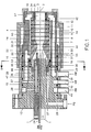
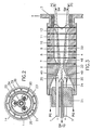
- the plasma channel 4 is formed by a number of ring-shaped neutrodes 6 to 12 which are electrically insulated from one another and the ring-shaped anode 3.
- the cathode rods 1 are anchored in a cathode support 13 made of insulating material.
- a sleeve-shaped one Anode carrier 14 made of insulating material, which surrounds the neutrodes 6 to 12 and the anode 3.
- the whole is held together by three metal sleeves 15, 16 and 17, the first sleeve 15 being screwed to the end on the end face and the second sleeve 16 being screwed to the first circumference, while the third sleeve 17 is loosely anchored on the one hand to the second sleeve 16 and on the other hand is screwed circumferentially to the anode carrier 14.
- the third sleeve 17 also presses with an inwardly directed flange 18 against the anode ring 3 and thus holds the elements forming the plasma channel 4 together, the neutrode 6 closest to the cathodes being supported on an inner collar 19 of the anode carrier 13.
- the free ends of the cathode rods 1 carry cathode pins 20, which are made of an electrically and thermally particularly conductive and, in addition, high-melting material, for example thoriated tungsten.
- the cathode pins 20 are arranged eccentrically to the respective axis of the cathode rods 1 in such a way that their longitudinal axes are closer to the central longitudinal axis 2 than those of the cathode rods 1.
- On the side facing the plasma channel 4 there is a central insulating body 21 of high-melting, in particular, on the side facing the plasma channel 4 glass-ceramic material from which the cathode pins 20 protrude into the cavity 22 of the inlet nozzle formed by the first neutrode 6.
- the exposed one Part of the outer circumferential surface of the insulating body 21 is located radially opposite a part of the nozzle wall and forms with this wall part an annular channel 23 for the inlet of the plasma gas into the nozzle cavity 22.
- the supply of the spray material SM, e.g. Metal or ceramic powder into the plasma jet is carried out with the aid of a carrier gas TG at the cathode-side end of the plasma channel 4.
- a pipe 24 running in the longitudinal axis 2 and held by the insulating body 21 is provided, which also opens into the nozzle cavity 22, whereby the cathode tips 20 extend beyond the mouth 25 of the tube 24.
- the plasma gas PG is fed through a transverse channel 26 provided in the cathode carrier 13, which transitions into a longitudinal channel 27, from which the plasma gas reaches an annular space 28 and from there into the annular channel 23.
- a distributor ring 29 is provided on the insulating body 21 and has a plurality of through bores 30 which connect the annular space 28 to the annular channel 23.
- the elements forming the plasma channel 4, namely the anode 3 and the neutrodes 6 to 12, are mutually electrical by means of ring disks 31 made of insulating material, for example boron nitride isolated and gas-tightly connected by sealing rings 32.
- the plasma channel 4 has a constriction zone 33 in the region near the cathode and, following this constriction zone 33, widens toward the anode 3 to a diameter which is at least 1.5 times as large as the channel diameter at the narrowest point of the constriction zone 33 this expansion, the plasma channel 4 runs cylindrical to its anode-side end.
- the anode 3 is made up of an outer ring 34, for example of copper, and an inner ring 35 of an electrically and thermally particularly conductive and also high-melting material, for example thoriated tungsten.
- the neutrode 6 closest to the cathode rods 1 extends over the entire constriction zone 33, so that the channel wall 52 unites beyond the narrowest point of the constriction zone has a steady course.
- the parts directly exposed to the arc and plasma heat are largely water-cooled.
- various cavities for the circulation of the cooling water KW are provided in the cathode holder 13, in the cathode rods 1 and in the anode holder 14.
- the cathode holder 13 has three annular spaces 36, 37 and 38, which are connected to connecting lines 39, 40 and 41, and the anode holder 14 has an annular space 42 in the region of the anode 3 and a cavity 43 surrounding all neutrodes in the region of the neutrodes 6 to 12.
- Cooling water KW is supplied via the connecting lines 39 and 41.
- the cooling water of the connecting line 39 first passes through a longitudinal channel 44 to the annular space 42 surrounding the most thermally stressed anode 3.
- the cooling water flows through the cavity 43 of the lateral surface of the neutrodes 6 to 12 back through a longitudinal channel 45 into the annular space 37
- the cooling water of the connecting line 41 flows into an annular space 38 and out of this into a respective cavity 46 of the cathode rods 1, which is divided by a cylindrical partition wall 47.
- the cooling water also arrives from the cathode rods 1 into the annular space 37, from which it flows out via the connecting line 40.
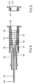
- FIG. 3 shows the approximate course of the arc 48 during operation of the plasma spraying device according to FIGS. 1 and 2, as well as the flow course of the plasma gas PG and the trajectory of the spraying material SM.
- the effect of the constriction zone 33 and the subsequent expansion of the plasma channel 4 can clearly be seen.
- the existence of the channel wall 50 to the plasma jet is relatively large. Under these circumstances, the channel wall 50 is thermally less stressed in this area, and the cooling capacity can be reduced accordingly.
- a single cathode 54 is provided, which is designed as a hollow cathode.
- the neutrode cascade 55 and the anode ring 56, which form the plasma channel 57, are constructed in principle in the same way as the corresponding parts in the embodiment according to FIG. 1, with the difference that the inlet nozzle 58 can run flat here and that the anode ring 56 has a larger inner diameter than the neutrode 59 closest to the anode ring 56.
- a tube 60 is inserted into the hollow cathode 54 for supplying the spray material, the mouth 61 of which protrudes towards the end of the cathode 54.
- An insulating tube 62 which projects beyond the mouth 61 of the tube 60 and fixes the tube 60 radially with a spacer ring 63, provides the necessary insulation between the cathode 54 and tube 60 and protects the latter from excessive heating.
- the plasma spraying device can be constructed identically or similarly to that according to FIG.
- FIG. 5 shows yet another embodiment of the anode 64, in which the inner wall 65 of the anode ring 66 used is conical to the outside.
Landscapes
- Physics & Mathematics (AREA)
- Engineering & Computer Science (AREA)
- Plasma & Fusion (AREA)
- Spectroscopy & Molecular Physics (AREA)
- Plasma Technology (AREA)
- Nozzles (AREA)
- Coating By Spraying Or Casting (AREA)
Claims (11)
- Appareil de pulvérisation par plasma de matériaux en poudre ou gazeux, équipé d'un plasmatron indirect pour la production d'un arc long, qui présente au moins une cathode (1, 20), une anode (3) annulaire et espacée de la cathode et un canal à plasma (4) s'étendant de la cathode à l'anode, lequel est constitué par la bague d'anode (3) et un nombre de neutrodes (6 à 12) annulaires et isolées électriquement les unes des autres, et équipé de moyens (24) se trouvant à l'extrémité côté cathode du canal à plasma pour une arrivée axiale du matériau à pulvériser (SM) dans le canal à plasma (4), caractérisé en ce que le canal à plasma (4) présente dans la zone proche de la cathode du trajet de l'arc une zone de rétrécissement (33) formée par un bombement de forme annulaire.
- Appareil de pulvérisation par plasma selon la revendication 1, caractérisé en ce que la partie élargie et consécutive à la zone de rétrécissement (30) du canal à plasma (4) présente une allure cylindrique.
- Appareil de pulvérisation par plasma selon la revendication 1, caractérisé en ce que la partie élargie et consécutive à la zone de rétrécissement (33) du canal à plasma (4) s'élargit en forme de cône en direction de l'anode (3) annulaire.
- Appareil de pulvérisation par plasma selon la revendication 1, caractérisé en ce que l'anode (56) annulaire présente un diamètre intérieur supérieur à la neutrode (59) voisine de l'anode (figure 4).
- Appareil de pulvérisation à plasma selon la revendication 1, caractérisé en ce que la surface interne (65) de l'anode (64) est élargie vers l'extérieur en forme de cône (figure 5).
- Appareil de pulvérisation à plasma selon la revendication 1, caractérisé en ce que le diamètre du canal à plasma (4) est au moins 1,5 fois aussi grand à l'extrémité côté anode qu'à l'endroit le plus resseré de la zone de rétrécissement (33).
- Appareil de pulvérisation à plasma, caractérisé en ce que la neutrode (6) la plus proche de la cathode (1,20) s'étend de l'extrémité côté cathode du canal à plasma (4) jusqu'au moins à l'endroit le plus resserré de la zone de rétrécissement (33).
- Appareil de pulvérisation à plasma selon la revendication 1, caractérisé en ce qu'il est prévu pour l'arrivée du matériau à pulvériser (SM) un tube (24) central qui est orienté axialement vers le canal à plasma (4) et dépasse dans la cavité (22) de la neutrode (6) située le plus près de la cathode (1,20).
- Appareil de pulvérisation à plasma selon la revendication 8, caractérisé en ce qu'il est prévu plusieurs cathodes (1,20) en forme de barres (1,20) qui sont réparties en cercle autour du tube central (24).
- Appareil de pulvérisation à plasma selon la revendication 9, caractérisé en ce que les cathodes (1,20) sont parallèles entre elles et réparties de façon symétrique autour du tube (24) central.
- Appareil de pulvérisation à plasma selon la revendication 8, caractérisé en ce qu'il est prévu comme cathode une cathode creuse (54) qui forme en même temps le tube (60) pour l'arrivée du matériau à pulvériser ou entoure un tube isolé de celle-ci (figure 4).
Applications Claiming Priority (2)
| Application Number | Priority Date | Filing Date | Title |
|---|---|---|---|
| DE4105408 | 1991-02-21 | ||
| DE4105408A DE4105408C1 (fr) | 1991-02-21 | 1991-02-21 |
Publications (2)
| Publication Number | Publication Date |
|---|---|
| EP0500491A1 EP0500491A1 (fr) | 1992-08-26 |
| EP0500491B1 true EP0500491B1 (fr) | 1995-10-18 |
Family
ID=6425560
Family Applications (1)
| Application Number | Title | Priority Date | Filing Date |
|---|---|---|---|
| EP92810094A Expired - Lifetime EP0500491B1 (fr) | 1991-02-21 | 1992-02-10 | Appareil de pulvérisation par plasma de matériaux en poudre ou gazeux |
Country Status (6)
| Country | Link |
|---|---|
| US (1) | US5225652A (fr) |
| EP (1) | EP0500491B1 (fr) |
| JP (1) | JP3258694B2 (fr) |
| AT (1) | ATE129378T1 (fr) |
| CA (1) | CA2061158C (fr) |
| DE (2) | DE4105408C1 (fr) |
Cited By (1)
| Publication number | Priority date | Publication date | Assignee | Title |
|---|---|---|---|---|
| EP1801256B2 (fr) † | 2005-12-21 | 2015-07-01 | Sulzer Metco (US) Inc. | Procedé hybride de Plasma-pulvérisation à froid et appareil |
Families Citing this family (45)
| Publication number | Priority date | Publication date | Assignee | Title |
|---|---|---|---|---|
| DE9215133U1 (de) * | 1992-11-06 | 1993-01-28 | Plasma-Technik Ag, Wohlen | Plasmaspritzgerät |
| US5444208A (en) * | 1993-03-29 | 1995-08-22 | Fmc Corporation | Multiple source plasma generation and injection device |
| US5464961A (en) * | 1993-09-10 | 1995-11-07 | Olin Corporation | Arcjet anode |
| DE19610015C2 (de) * | 1996-03-14 | 1999-12-02 | Hoechst Ag | Thermisches Auftragsverfahren für dünne keramische Schichten und Vorrichtung zum Auftragen |
| US5573682A (en) * | 1995-04-20 | 1996-11-12 | Plasma Processes | Plasma spray nozzle with low overspray and collimated flow |
| DE19540587A1 (de) * | 1995-10-31 | 1997-05-07 | Bosch Gmbh Robert | Plasmabrenner |
| ATE185465T1 (de) * | 1996-12-23 | 1999-10-15 | Sulzer Metco Ag | Indirektes plasmatron |
| US6114649A (en) * | 1999-07-13 | 2000-09-05 | Duran Technologies Inc. | Anode electrode for plasmatron structure |
| US6202939B1 (en) | 1999-11-10 | 2001-03-20 | Lucian Bogdan Delcea | Sequential feedback injector for thermal spray torches |
| DE19963904C2 (de) * | 1999-12-31 | 2001-12-06 | Gtv Ges Fuer Thermischen Versc | Plasmabrenner und Verfahren zur Erzeugung eines Plasmastrahls |
| RS49706B (sr) * | 2000-02-24 | 2007-12-31 | Miroljub Vilotijević | Jednosmerni lučni plazma generator sa ulaznom volt- amperskom karakteristikom |
| GB0011080D0 (en) * | 2000-05-08 | 2000-06-28 | Wang Wang N | Electrodes and plasma generating devices including electrodes |
| US6392189B1 (en) | 2001-01-24 | 2002-05-21 | Lucian Bogdan Delcea | Axial feedstock injector for thermal spray torches |
| US6669106B2 (en) | 2001-07-26 | 2003-12-30 | Duran Technologies, Inc. | Axial feedstock injector with single splitting arm |
| SE523135C2 (sv) * | 2002-09-17 | 2004-03-30 | Smatri Ab | Plasmasprutningsanordning |
| WO2005093394A1 (fr) * | 2004-03-25 | 2005-10-06 | Japan Advanced Institute Of Science And Technology | Equipement de generation de plasma |
| EP1880034B1 (fr) * | 2005-05-02 | 2016-11-02 | National Research Council Of Canada | Procede et appareil destines a la suspension de particules fines dans un liquide, destine a un systeme d'aerosol thermique, et revetements formes au moyen de ces procede et appareil |
| SE529056C2 (sv) | 2005-07-08 | 2007-04-17 | Plasma Surgical Invest Ltd | Plasmaalstrande anordning, plasmakirurgisk anordning och användning av en plasmakirurgisk anordning |
| SE529053C2 (sv) | 2005-07-08 | 2007-04-17 | Plasma Surgical Invest Ltd | Plasmaalstrande anordning, plasmakirurgisk anordning och användning av en plasmakirurgisk anordning |
| SE529058C2 (sv) * | 2005-07-08 | 2007-04-17 | Plasma Surgical Invest Ltd | Plasmaalstrande anordning, plasmakirurgisk anordning, användning av en plasmakirurgisk anordning och förfarande för att bilda ett plasma |
| US7928338B2 (en) * | 2007-02-02 | 2011-04-19 | Plasma Surgical Investments Ltd. | Plasma spraying device and method |
| US8142619B2 (en) * | 2007-05-11 | 2012-03-27 | Sdc Materials Inc. | Shape of cone and air input annulus |
| EP1993329A1 (fr) * | 2007-05-15 | 2008-11-19 | Max-Planck-Gesellschaft zur Förderung der Wissenschaften e.V. | Source de plasma |
| US7589473B2 (en) * | 2007-08-06 | 2009-09-15 | Plasma Surgical Investments, Ltd. | Pulsed plasma device and method for generating pulsed plasma |
| EP3062589B1 (fr) * | 2007-08-06 | 2024-08-28 | Plasma Surgical, Inc. | Procédé de génération d'un plasma pulsé |
| EP2557902B1 (fr) * | 2007-08-06 | 2016-11-23 | Plasma Surgical Investments Limited | Ensemble cathodique et procédé de génération de plasma pulsé |
| US8735766B2 (en) * | 2007-08-06 | 2014-05-27 | Plasma Surgical Investments Limited | Cathode assembly and method for pulsed plasma generation |
| US8575059B1 (en) | 2007-10-15 | 2013-11-05 | SDCmaterials, Inc. | Method and system for forming plug and play metal compound catalysts |
| US8237079B2 (en) * | 2009-09-01 | 2012-08-07 | General Electric Company | Adjustable plasma spray gun |
| US9315888B2 (en) | 2009-09-01 | 2016-04-19 | General Electric Company | Nozzle insert for thermal spray gun apparatus |
| DE102009048397A1 (de) * | 2009-10-06 | 2011-04-07 | Plasmatreat Gmbh | Atmosphärendruckplasmaverfahren zur Herstellung oberflächenmodifizierter Partikel und von Beschichtungen |
| US8613742B2 (en) | 2010-01-29 | 2013-12-24 | Plasma Surgical Investments Limited | Methods of sealing vessels using plasma |
| US9089319B2 (en) | 2010-07-22 | 2015-07-28 | Plasma Surgical Investments Limited | Volumetrically oscillating plasma flows |
| EP2535437A1 (fr) | 2011-06-16 | 2012-12-19 | RH Optronic ApS | Procédé de revêtement au plasma de rouleaux et rouleau revêtu au plasma |
| CN103260330B (zh) * | 2012-02-21 | 2015-11-11 | 成都真火科技有限公司 | 一种多阴极中轴阳极电弧等离子体发生器 |
| US9150949B2 (en) * | 2012-03-08 | 2015-10-06 | Vladmir E. BELASHCHENKO | Plasma systems and methods including high enthalpy and high stability plasmas |
| CN102618815B (zh) * | 2012-05-09 | 2014-05-21 | 厦门映日新材料科技有限公司 | 等离子体射流保护罩 |
| US9272360B2 (en) | 2013-03-12 | 2016-03-01 | General Electric Company | Universal plasma extension gun |
| WO2015013545A1 (fr) | 2013-07-25 | 2015-01-29 | SDCmaterials, Inc. | Revêtements catalytiques et substrats revêtus pour convertisseurs catalytiques |
| WO2015061477A1 (fr) | 2013-10-22 | 2015-04-30 | SDCmaterials, Inc. | Conception de catalyseurs pour moteurs à combustion diesel de grande puissance |
| US9687811B2 (en) | 2014-03-21 | 2017-06-27 | SDCmaterials, Inc. | Compositions for passive NOx adsorption (PNA) systems and methods of making and using same |
| CN105171215B (zh) * | 2015-10-16 | 2017-07-04 | 吴忠仪表有限责任公司 | 分体式等离子喷嘴 |
| CH712835A1 (de) * | 2016-08-26 | 2018-02-28 | Amt Ag | Plasmaspritzvorrichtung. |
| EP3742869A1 (fr) | 2019-05-22 | 2020-11-25 | Gulhfi Consulting AG | Torche à plasma miniaturisée |
| IL300972A (en) | 2020-08-28 | 2023-04-01 | Plasma Surgical Invest Ltd | Systems, methods and devices for producing radially expanded plasma flow |
Citations (4)
| Publication number | Priority date | Publication date | Assignee | Title |
|---|---|---|---|---|
| DE1932150U (de) * | 1965-09-24 | 1966-02-03 | Siemens Ag | Plasmaspritzpistole. |
| WO1990003095A1 (fr) * | 1988-09-13 | 1990-03-22 | Commonwealth Scientific And Industrial Research Organisation | Dispositif generateur d'arc electrique |
| WO1990015516A1 (fr) * | 1989-06-08 | 1990-12-13 | Suennen Jean | Procede et dispositif d'obtention de hautes temperatures |
| WO1991005449A1 (fr) * | 1989-10-05 | 1991-04-18 | Centre National De La Recherche Scientifique (Cnrs) | Generateur de plasma a cathode creuse pour le traitement de poudres par plasma |
Family Cites Families (15)
| Publication number | Priority date | Publication date | Assignee | Title |
|---|---|---|---|---|
| DE1819916U (de) * | 1959-04-02 | 1960-10-20 | Union Carbide Corp | Vorrichtung zum betreiben eines elektrischen lichtbogens. |
| US3106633A (en) * | 1961-04-21 | 1963-10-08 | Union Carbide Corp | Arc torch device |
| US3239130A (en) * | 1963-07-10 | 1966-03-08 | Cons Vacuum Corp | Gas pumping methods and apparatus |
| US3360988A (en) * | 1966-11-22 | 1968-01-02 | Nasa Usa | Electric arc apparatus |
| US3839618A (en) * | 1972-01-03 | 1974-10-01 | Geotel Inc | Method and apparatus for effecting high-energy dynamic coating of substrates |
| DE2246300A1 (de) * | 1972-08-16 | 1974-02-28 | Lonza Ag | Plasmabrenner |
| JPS5546266A (en) * | 1978-09-28 | 1980-03-31 | Daido Steel Co Ltd | Plasma torch |
| SE448509B (sv) * | 1982-02-15 | 1987-02-23 | Ceskoslovenska Akademie Ved | Forfarande for stabilisering av lagtemperaturplasma i en ljusbagsbrennare samt vetskestabiliserad plasmabrennare |
| ZA832387B (en) * | 1982-04-06 | 1983-12-28 | Arnoldy Roman F | Plasma melting apparatus |
| US4577461A (en) * | 1983-06-22 | 1986-03-25 | Cann Gordon L | Spacecraft optimized arc rocket |
| EP0157407A3 (fr) * | 1984-04-04 | 1986-12-03 | General Electric Company | Méthode et appareil pour produire un flux de plasma avec un jet de plasma chauffé et chargé |
| USRE32908E (en) * | 1984-09-27 | 1989-04-18 | Regents Of The University Of Minnesota | Method of utilizing a plasma column |
| US4780591A (en) * | 1986-06-13 | 1988-10-25 | The Perkin-Elmer Corporation | Plasma gun with adjustable cathode |
| US4882465A (en) * | 1987-10-01 | 1989-11-21 | Olin Corporation | Arcjet thruster with improved arc attachment for enhancement of efficiency |
| US4990739A (en) * | 1989-07-07 | 1991-02-05 | The United States Of America As Represented By The Administrator Of The National Aeronautics And Space Administration | Plasma gun with coaxial powder feed and adjustable cathode |
-
1991
- 1991-02-21 DE DE4105408A patent/DE4105408C1/de not_active Expired - Lifetime
-
1992
- 1992-02-10 EP EP92810094A patent/EP0500491B1/fr not_active Expired - Lifetime
- 1992-02-10 DE DE59204023T patent/DE59204023D1/de not_active Expired - Lifetime
- 1992-02-10 AT AT92810094T patent/ATE129378T1/de active
- 1992-02-12 US US07/836,046 patent/US5225652A/en not_active Expired - Lifetime
- 1992-02-13 CA CA002061158A patent/CA2061158C/fr not_active Expired - Lifetime
- 1992-02-21 JP JP03534692A patent/JP3258694B2/ja not_active Expired - Lifetime
Patent Citations (4)
| Publication number | Priority date | Publication date | Assignee | Title |
|---|---|---|---|---|
| DE1932150U (de) * | 1965-09-24 | 1966-02-03 | Siemens Ag | Plasmaspritzpistole. |
| WO1990003095A1 (fr) * | 1988-09-13 | 1990-03-22 | Commonwealth Scientific And Industrial Research Organisation | Dispositif generateur d'arc electrique |
| WO1990015516A1 (fr) * | 1989-06-08 | 1990-12-13 | Suennen Jean | Procede et dispositif d'obtention de hautes temperatures |
| WO1991005449A1 (fr) * | 1989-10-05 | 1991-04-18 | Centre National De La Recherche Scientifique (Cnrs) | Generateur de plasma a cathode creuse pour le traitement de poudres par plasma |
Non-Patent Citations (1)
| Title |
|---|
| Rutscher/Deutsch: Plasmatechnik, Seiten 244, 245, 262, 263 * |
Cited By (1)
| Publication number | Priority date | Publication date | Assignee | Title |
|---|---|---|---|---|
| EP1801256B2 (fr) † | 2005-12-21 | 2015-07-01 | Sulzer Metco (US) Inc. | Procedé hybride de Plasma-pulvérisation à froid et appareil |
Also Published As
| Publication number | Publication date |
|---|---|
| EP0500491A1 (fr) | 1992-08-26 |
| CA2061158C (fr) | 1998-06-30 |
| JP3258694B2 (ja) | 2002-02-18 |
| DE4105408C1 (fr) | 1992-09-17 |
| ATE129378T1 (de) | 1995-11-15 |
| DE59204023D1 (de) | 1995-11-23 |
| JPH0584454A (ja) | 1993-04-06 |
| CA2061158A1 (fr) | 1992-08-22 |
| US5225652A (en) | 1993-07-06 |
Similar Documents
| Publication | Publication Date | Title |
|---|---|---|
| EP0500491B1 (fr) | Appareil de pulvérisation par plasma de matériaux en poudre ou gazeux | |
| DE4105407C2 (fr) | ||
| EP0596830B1 (fr) | Appareil de pulvérisation par plasma | |
| DE2164270C3 (de) | Plasmastrahlgenerator | |
| DE69122890T2 (de) | Plasmafackel | |
| DE69506818T2 (de) | Verfahren und Vorrichtung zum Auftragen einer Schicht auf ein Substrat durch thermisches Verspritzen | |
| DE69525162T2 (de) | Plasmabrenner mit axialer pulverinjektion | |
| DE2912843A1 (de) | Plasmabrenner, plasmabrenneranordnung und verfahren zur plasmaerzeugung | |
| DE3929960A1 (de) | Duese fuer einen plasmabrenner und verfahren zum einbringen eines pulvers in die plasmaflamme eines plasmabrenners | |
| DE4030541C2 (de) | Brenner zur Beschichtung von Grundwerkstoffen mit pulverförmigen Zusatzwerkstoffen | |
| EP0017201B1 (fr) | Chalumeau à plasma à courant continu | |
| DE60206162T2 (de) | Plasmabrenner | |
| DE2241972A1 (de) | Verfahren und vorrichtung zur thermischen bearbeitung und verarbeitung hochschmelzender materialien | |
| DE19963904C2 (de) | Plasmabrenner und Verfahren zur Erzeugung eines Plasmastrahls | |
| DE69300563T2 (de) | Lichtbogenplasmabrenner mit konische Bohrung enthaltender Elektrode. | |
| DE1764116B1 (de) | Lichtbogen plasmastrahlgenerator | |
| DE1940040A1 (de) | Plasmabrenner | |
| DE2229716A1 (de) | Verfahren und einrichtung zur energiebeladung eines reaktionsfaehigen werkstoffs mittels einer bogenentladung | |
| WO1997016947A1 (fr) | Chalumeau a plasma | |
| DE10010706A1 (de) | Hohlkathoden-Sputter-Ionenquelle zur Erzeugung von Ionenstrahlen hoher Intensität | |
| DE2638094C3 (de) | Vakuum-Lichtbogen-Erwärmungseinrichtung | |
| DE1564123A1 (de) | Einrichtung zum Erzeugen eines heissen Plasmastrahles | |
| DE102016120416A1 (de) | Elektronenstrahlquelle, Elektronenkanone und Prozessieranordnung | |
| DE1229882B (de) | Lichtbogenspritzpistole | |
| AT224772B (de) | Lichtbogenheizeinrichtung für Gase |
Legal Events
| Date | Code | Title | Description |
|---|---|---|---|
| PUAI | Public reference made under article 153(3) epc to a published international application that has entered the european phase |
Free format text: ORIGINAL CODE: 0009012 |
|
| AK | Designated contracting states |
Kind code of ref document: A1 Designated state(s): AT BE CH DE DK ES FR GB GR IT LI LU MC NL PT SE |
|
| 17P | Request for examination filed |
Effective date: 19921015 |
|
| 17Q | First examination report despatched |
Effective date: 19940831 |
|
| RAP1 | Party data changed (applicant data changed or rights of an application transferred) |
Owner name: SULZER METCO AG |
|
| GRAA | (expected) grant |
Free format text: ORIGINAL CODE: 0009210 |
|
| AK | Designated contracting states |
Kind code of ref document: B1 Designated state(s): AT BE CH DE DK ES FR GB GR IT LI LU MC NL PT SE |
|
| PG25 | Lapsed in a contracting state [announced via postgrant information from national office to epo] |
Ref country code: MC Free format text: LAPSE BECAUSE OF NON-PAYMENT OF DUE FEES Effective date: 19951018 Ref country code: GR Free format text: LAPSE BECAUSE OF FAILURE TO SUBMIT A TRANSLATION OF THE DESCRIPTION OR TO PAY THE FEE WITHIN THE PRESCRIBED TIME-LIMIT Effective date: 19951018 Ref country code: ES Free format text: THE PATENT HAS BEEN ANNULLED BY A DECISION OF A NATIONAL AUTHORITY Effective date: 19951018 Ref country code: DK Effective date: 19951018 |
|
| REF | Corresponds to: |
Ref document number: 129378 Country of ref document: AT Date of ref document: 19951115 Kind code of ref document: T |
|
| REF | Corresponds to: |
Ref document number: 59204023 Country of ref document: DE Date of ref document: 19951123 |
|
| ET | Fr: translation filed | ||
| GBT | Gb: translation of ep patent filed (gb section 77(6)(a)/1977) |
Effective date: 19951123 |
|
| ITF | It: translation for a ep patent filed | ||
| PG25 | Lapsed in a contracting state [announced via postgrant information from national office to epo] |
Ref country code: SE Effective date: 19960118 Ref country code: PT Effective date: 19960118 |
|
| PLBE | No opposition filed within time limit |
Free format text: ORIGINAL CODE: 0009261 |
|
| STAA | Information on the status of an ep patent application or granted ep patent |
Free format text: STATUS: NO OPPOSITION FILED WITHIN TIME LIMIT |
|
| 26N | No opposition filed | ||
| PGFP | Annual fee paid to national office [announced via postgrant information from national office to epo] |
Ref country code: AT Payment date: 19970116 Year of fee payment: 6 |
|
| PGFP | Annual fee paid to national office [announced via postgrant information from national office to epo] |
Ref country code: BE Payment date: 19970127 Year of fee payment: 6 |
|
| PGFP | Annual fee paid to national office [announced via postgrant information from national office to epo] |
Ref country code: LU Payment date: 19970219 Year of fee payment: 6 |
|
| PG25 | Lapsed in a contracting state [announced via postgrant information from national office to epo] |
Ref country code: LU Free format text: LAPSE BECAUSE OF NON-PAYMENT OF DUE FEES Effective date: 19980210 Ref country code: AT Free format text: LAPSE BECAUSE OF NON-PAYMENT OF DUE FEES Effective date: 19980210 |
|
| PG25 | Lapsed in a contracting state [announced via postgrant information from national office to epo] |
Ref country code: BE Free format text: LAPSE BECAUSE OF NON-PAYMENT OF DUE FEES Effective date: 19980228 |
|
| BERE | Be: lapsed |
Owner name: SULZER METCO A.G. Effective date: 19980228 |
|
| REG | Reference to a national code |
Ref country code: GB Ref legal event code: IF02 |
|
| REG | Reference to a national code |
Ref country code: CH Ref legal event code: NV Representative=s name: SULZER MANAGEMENT AG |
|
| PGFP | Annual fee paid to national office [announced via postgrant information from national office to epo] |
Ref country code: DE Payment date: 20110218 Year of fee payment: 20 Ref country code: CH Payment date: 20110222 Year of fee payment: 20 Ref country code: IT Payment date: 20110221 Year of fee payment: 20 Ref country code: FR Payment date: 20110302 Year of fee payment: 20 Ref country code: NL Payment date: 20110216 Year of fee payment: 20 |
|
| PGFP | Annual fee paid to national office [announced via postgrant information from national office to epo] |
Ref country code: GB Payment date: 20110217 Year of fee payment: 20 |
|
| REG | Reference to a national code |
Ref country code: DE Ref legal event code: R071 Ref document number: 59204023 Country of ref document: DE |
|
| REG | Reference to a national code |
Ref country code: DE Ref legal event code: R071 Ref document number: 59204023 Country of ref document: DE |
|
| REG | Reference to a national code |
Ref country code: CH Ref legal event code: PL |
|
| REG | Reference to a national code |
Ref country code: NL Ref legal event code: V4 Effective date: 20120210 |
|
| REG | Reference to a national code |
Ref country code: GB Ref legal event code: PE20 Expiry date: 20120209 |
|
| PG25 | Lapsed in a contracting state [announced via postgrant information from national office to epo] |
Ref country code: DE Free format text: LAPSE BECAUSE OF EXPIRATION OF PROTECTION Effective date: 20120211 |
|
| PG25 | Lapsed in a contracting state [announced via postgrant information from national office to epo] |
Ref country code: GB Free format text: LAPSE BECAUSE OF EXPIRATION OF PROTECTION Effective date: 20120209 |