EP0500309B1 - Work holding device - Google Patents
Work holding device Download PDFInfo
- Publication number
- EP0500309B1 EP0500309B1 EP92301301A EP92301301A EP0500309B1 EP 0500309 B1 EP0500309 B1 EP 0500309B1 EP 92301301 A EP92301301 A EP 92301301A EP 92301301 A EP92301301 A EP 92301301A EP 0500309 B1 EP0500309 B1 EP 0500309B1
- Authority
- EP
- European Patent Office
- Prior art keywords
- toothed pulley
- fixed
- holding device
- work
- swivel head
- Prior art date
- Legal status (The legal status is an assumption and is not a legal conclusion. Google has not performed a legal analysis and makes no representation as to the accuracy of the status listed.)
- Expired - Lifetime
Links
Images


Classifications
-
- B—PERFORMING OPERATIONS; TRANSPORTING
- B23—MACHINE TOOLS; METAL-WORKING NOT OTHERWISE PROVIDED FOR
- B23Q—DETAILS, COMPONENTS, OR ACCESSORIES FOR MACHINE TOOLS, e.g. ARRANGEMENTS FOR COPYING OR CONTROLLING; MACHINE TOOLS IN GENERAL CHARACTERISED BY THE CONSTRUCTION OF PARTICULAR DETAILS OR COMPONENTS; COMBINATIONS OR ASSOCIATIONS OF METAL-WORKING MACHINES, NOT DIRECTED TO A PARTICULAR RESULT
- B23Q3/00—Devices holding, supporting, or positioning work or tools, of a kind normally removable from the machine
-
- B—PERFORMING OPERATIONS; TRANSPORTING
- B23—MACHINE TOOLS; METAL-WORKING NOT OTHERWISE PROVIDED FOR
- B23Q—DETAILS, COMPONENTS, OR ACCESSORIES FOR MACHINE TOOLS, e.g. ARRANGEMENTS FOR COPYING OR CONTROLLING; MACHINE TOOLS IN GENERAL CHARACTERISED BY THE CONSTRUCTION OF PARTICULAR DETAILS OR COMPONENTS; COMBINATIONS OR ASSOCIATIONS OF METAL-WORKING MACHINES, NOT DIRECTED TO A PARTICULAR RESULT
- B23Q1/00—Members which are comprised in the general build-up of a form of machine, particularly relatively large fixed members
- B23Q1/25—Movable or adjustable work or tool supports
- B23Q1/44—Movable or adjustable work or tool supports using particular mechanisms
- B23Q1/50—Movable or adjustable work or tool supports using particular mechanisms with rotating pairs only, the rotating pairs being the first two elements of the mechanism
- B23Q1/54—Movable or adjustable work or tool supports using particular mechanisms with rotating pairs only, the rotating pairs being the first two elements of the mechanism two rotating pairs only
- B23Q1/5468—Movable or adjustable work or tool supports using particular mechanisms with rotating pairs only, the rotating pairs being the first two elements of the mechanism two rotating pairs only a single rotating pair followed parallelly by a single rotating pair
- B23Q1/5481—Movable or adjustable work or tool supports using particular mechanisms with rotating pairs only, the rotating pairs being the first two elements of the mechanism two rotating pairs only a single rotating pair followed parallelly by a single rotating pair followed parallelly by a single rotating pair
-
- B—PERFORMING OPERATIONS; TRANSPORTING
- B23—MACHINE TOOLS; METAL-WORKING NOT OTHERWISE PROVIDED FOR
- B23Q—DETAILS, COMPONENTS, OR ACCESSORIES FOR MACHINE TOOLS, e.g. ARRANGEMENTS FOR COPYING OR CONTROLLING; MACHINE TOOLS IN GENERAL CHARACTERISED BY THE CONSTRUCTION OF PARTICULAR DETAILS OR COMPONENTS; COMBINATIONS OR ASSOCIATIONS OF METAL-WORKING MACHINES, NOT DIRECTED TO A PARTICULAR RESULT
- B23Q1/00—Members which are comprised in the general build-up of a form of machine, particularly relatively large fixed members
- B23Q1/25—Movable or adjustable work or tool supports
- B23Q1/44—Movable or adjustable work or tool supports using particular mechanisms
- B23Q1/48—Movable or adjustable work or tool supports using particular mechanisms with sliding pairs and rotating pairs
- B23Q1/4852—Movable or adjustable work or tool supports using particular mechanisms with sliding pairs and rotating pairs a single sliding pair followed perpendicularly by a single rotating pair
- B23Q1/4857—Movable or adjustable work or tool supports using particular mechanisms with sliding pairs and rotating pairs a single sliding pair followed perpendicularly by a single rotating pair followed perpendicularly by a single rotating pair
-
- Y—GENERAL TAGGING OF NEW TECHNOLOGICAL DEVELOPMENTS; GENERAL TAGGING OF CROSS-SECTIONAL TECHNOLOGIES SPANNING OVER SEVERAL SECTIONS OF THE IPC; TECHNICAL SUBJECTS COVERED BY FORMER USPC CROSS-REFERENCE ART COLLECTIONS [XRACs] AND DIGESTS
- Y10—TECHNICAL SUBJECTS COVERED BY FORMER USPC
- Y10T—TECHNICAL SUBJECTS COVERED BY FORMER US CLASSIFICATION
- Y10T29/00—Metal working
- Y10T29/51—Plural diverse manufacturing apparatus including means for metal shaping or assembling
- Y10T29/5104—Type of machine
- Y10T29/5105—Drill press
- Y10T29/5107—Drilling and other
-
- Y—GENERAL TAGGING OF NEW TECHNOLOGICAL DEVELOPMENTS; GENERAL TAGGING OF CROSS-SECTIONAL TECHNOLOGIES SPANNING OVER SEVERAL SECTIONS OF THE IPC; TECHNICAL SUBJECTS COVERED BY FORMER USPC CROSS-REFERENCE ART COLLECTIONS [XRACs] AND DIGESTS
- Y10—TECHNICAL SUBJECTS COVERED BY FORMER USPC
- Y10T—TECHNICAL SUBJECTS COVERED BY FORMER US CLASSIFICATION
- Y10T408/00—Cutting by use of rotating axially moving tool
- Y10T408/36—Machine including plural tools
- Y10T408/37—Turret of tools
Definitions
- the present invention relates to a novel work holding device and, more specifically, to a work holding device that enables a work to be set for machining or assembling in an optional position relative to a tool.
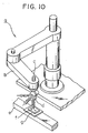
- Fig. 10 of the accompanying drawings shows, by way of example, a conventional work holding device in combination with an industrial robot for machining a word held by the work holding device or joining parts to the same.
- a horizontal articulated robot a has an arm b, and a tool holding shaft c supported for rotation and axial movement on the free end of the arm b. Tools d are held on the lower end of the tool holding shaft c.
- a conveying device e is disposed under the operating region of the articulated robot a to convey a work f mounted on a work mount g through the operating region of the articulated robot a. The tool holding shaft c is lowered to machine the work f with the tools d.
- This work holding device has the work mount g merely fixedly holding the work f, and the work mount g cannot he tilted with respect to a processing direction along which the articulated robot a moves the tools d. Therefore, the articulated robot a is unable to gain access to the lateral side of the work f, for example, for fastening a screw to the lateral side of the work f. Accordingly, it has been a practice to design a work so that the work does not require lateral processing operation in joining parts to the work or in machining the work. However, it requires much time for designing a work to take conditions for eliminating lateral processing operation into consideration, and it is difficult to process a work designed to meet multiple purposes along limited processing directions.
- DE-A-3511614 discloses a machine tool which includes a workpiece holding means in accordance with the precharacterizing portion of claim 1.
- the holding means comprises a rotary table capable of rotation in a horizontal plane and vertical movement with separate tools provided for working on the top or sides of the work piece.
- a work holding device comprises a base plate extending in a first direction; a slide base for movement in said first direction on the front surface of the base plate and supporting a rotary table; characterized by and L-shaped swivel head having a main section extending parallel to the slide base and connected thereto for rotation about an axis perpendicular to said first direction, and an arm section extending perpendicularly to the front from the main section; and in that the rotary table is supported for roration on the extremity of the arm section of the swivel head.
- the work holding device in accordance with the present invention does not place restrictions on the processing direction of an industrial robot or the like, enables processing a work along many directions, does not place restrictions related with processing direction on the design of a work, enables the curtailment of time for designing a work, and increases the degree of freedom of design.
- An assembling apparatus comprising, in combination, a work holding device in a preferred embodiment according to the present invention and a horizontal articulated robot will be described briefly with reference to Figs. 1 to 4 prior to the detailed description of the work holding device.
- an assembling apparatus 1 comprises a horizontal articulated robot 2 provided with a turret tool head 13, and a work holding device 7.
- the articulated robot 2 and the work holding device 7 are controlled synchronously for cooperative operation by a robot controller 14 according to a robot control program.
- the articulated robot 2 has an arm 3, and a tool holding shaft 4 supported for rotation and axial movement on the free end of the arm 3.
- the articulated robot 2 is installed fixedly on a bed 6.
- the work holding device 7 has a base plate 8 fixed at its upper end to the bed 6 so as to extend vertically.
- a slide base 9 is supported for vertical movement on the front surface of the base plate 8.
- a swivel head 10 is supported for turning in a vertical plane about a horizontal axis on the front surface of the slide base 9.
- a rotary table 11 is supported for rotation about an axis perpendicular to the axis of turning of the swivel head 10 on the upper surface of the arm section 31 of the swivel head 10.
- a work mount supporting a work 12 is held on the rotary table 11.
- the work 12 In processing the work 12 held on the rotary table 11 indicated by continuous lines in Fig. 2 by the articulated robot 2, the work 12 can be processed from above the same.
- the swivel head 10 is turned on the slide base 9 to set the work 12 in a position indicated by alternate long and two short dashes lines or in a position indicated by alternate long and short dash line in Fig. 2.
- the positions of the work 12 are not limited to those indicated by continuous lines, alternate long and two short dashes lines and alternate long and short dash line; the work 12 can be set in any position between the position indicated by continuous lines and the position indicated by alternate long and two short dashes lines and between the position indicated by continuous lines and the position indicated by alternate long and short dash lines by turning the swivel head 10 to an appropriate angular position.
- the diversity of positions of the work 12 can be enhanced by turning the rotary table 11 relative to the swivel head 10 in addition to the turning of the swivel head 10 about the horizontal axis. For example, the work 12 held in a position indicated by continuous lines in Fig.
- Fig. 3 corresponding to the right side view of the same in the position indicated by alternate long and two short dashes lines in Fig. 2 can be set in an optional position between the position indicated by continuous lines and the position indicated by alternate long and two short dashes lines in Fig. 3 by turning the rotary table 11 to a corresponding angular position.
- the slide base 9 is moved vertically in changing the position of the work 12, in changing a tool of a plurality of tools held on the turret tool head 13 held on the tool holding shaft 4 as shown in Fig. 4 for another one or in adjusting the position of the work 12 relative to the tool.
- the rotary table 11 is provided with compressed air piping, a work holding means, sensors for detecting the position of the work 12 and the operating condition of the associated mechanisms and wiring for the sensors, which are not shown in the drawings.
- the work holding device 7 will be described in detail hereinafter.
- a screw rod 15 is journaled at its upper end and in a portion near its lower end on the left-hand portion of the front surface of the base plate 8.
- a driven toothed pulley 16 is fixed to the lower end of the screw rod 15.
- a bracket 18 is attached to the base plate 8 at a position near the lower end of the base plate 8 so as to project to the front, and a motor 19 is fixedly held on the bracket 18 with its output shaft 19a projecting downward from the bracket 18.
- a driving toothed pulley 20 is fixed to the output shaft 19a and an endless timing belt 21 is extended between the driven toothed pulley 16 and the driving toothed pulley 20.
- an internally threaded block 24 is fixed to the left side of the slide base 9 and is in engagement with the screw rod 15.
- Thin guide blocks 17 provided respectively with guide grooves 17a in their front surfaces are fixed to the front surface of the base plate 8 respectively at an upper right-hand position, an upper left-hand position, a lower right-hand position and a lower left-hand position with their guide grooves 17a vertically extended.
- Rails 23 are fixed to the back surface of the slide base 9 respectively along the opposite sides thereof. The rails 23 are received in the guide grooves 17a for vertical sliding movement along the guide grooves 17a.
- the cross section of the rails 23 is complementary to that of the guide grooves 17a.
- the rotation of the output shaft 19a of the motor 19 is transmitted through the driving toothed pulley 20, the timing belt 21 and the driven toothed pulley 16 to the screw rod 15 to move the nut 24 engaging the screw rod 15 upward or downward according to the direction of rotation of the output shaft 19a of the motor 19, so that the slide base 9 is moved upward or downward according to the direction of rotation of the output shaft 19a of the motor 19.
- a vertically elongate support block 25 is fixed to the front surface of the slide base 9.
- a motor 26 is fixed to the lower end of the support block 25 with its axis extended horizontally.
- a driving toothed pulley 27 is fixed to the output shaft 26a of the motor 26.
- a support shaft 28 is projected to the front from the support block 25 from a position near the upper end of the support block 25.
- a boxed-shaped member 29 for the swivel block 10 has a vertical main section 30 and an arm section 31 projecting to the front from the lower end of the main section 30 in an integral construction.
- the arm section is tapered toward its front end.
- the main section is journaled in its substantially central portion on the front portion of the support shaft 28 provided on the slide base 9.
- a driven toothed pulley 32 is fixed to the substantially central portion of the back surface of the main section 30 coaxially with the support shaft 28 so as to surround the front end of a portion of the support block 25 supporting the support shaft 28.
- An endless timing belt 33 is extended between the driving toothed pulley 27 and the driven toothed pulley 32 to transmit the rotation of the output shaft 26a of the motor 26 through the driven toothed pulley 32 to the swivel block 10 to turn the swivel block 10 about a horizontal axis.
- a motor 34 is fixed to the arm section 31 at a position near the main section 30 with its axis in a vertical position.
- the output shaft 34a of the motor 34 projects downward from the arm section 31 and a driving toothed pulley 35 is fixed to the output shaft 34a.
- a rotary shaft 36 is journaled in a vertical position on the front end of the arm section 31, and a driven toothed pulley 37 is fixed to a portion of the rotary shaft 36 projecting downward from the arm section 31.
- An endless timing belt 38 is extended between the driving toothed pulley 35 and the driven toothed pulley 37.
- the rotary table 11 is fixed to the upper end of the rotary shaft 36 projecting upward from the arm section 31.
- the motor 34 drives the rotary shaft 36 for rotation through the driving toothed pulley 35, the timing belt 38 and the driven toothed pulley 37 to rotate the rotary table 11.
- the operation of the two motors 26 and 34 is controlled properly to set the work held on the rotary table 11 in an optional position, so that the work 12 can be processed from different directions.
- the motor 19 is driven to change the height of the work 12 relative to the articulated robot 2.
Landscapes
- Engineering & Computer Science (AREA)
- Mechanical Engineering (AREA)
- Manipulator (AREA)
- Machine Tool Units (AREA)
- Specific Conveyance Elements (AREA)
Applications Claiming Priority (2)
| Application Number | Priority Date | Filing Date | Title |
|---|---|---|---|
| JP3045505A JPH04269139A (ja) | 1991-02-19 | 1991-02-19 | ワーク保持装置 |
| JP45505/91 | 1991-02-19 |
Publications (3)
| Publication Number | Publication Date |
|---|---|
| EP0500309A2 EP0500309A2 (en) | 1992-08-26 |
| EP0500309A3 EP0500309A3 (en) | 1993-01-20 |
| EP0500309B1 true EP0500309B1 (en) | 1995-04-19 |
Family
ID=12721272
Family Applications (1)
| Application Number | Title | Priority Date | Filing Date |
|---|---|---|---|
| EP92301301A Expired - Lifetime EP0500309B1 (en) | 1991-02-19 | 1992-02-18 | Work holding device |
Country Status (7)
| Country | Link |
|---|---|
| US (1) | US5298844A (enExample) |
| EP (1) | EP0500309B1 (enExample) |
| JP (1) | JPH04269139A (enExample) |
| KR (1) | KR100226247B1 (enExample) |
| DE (1) | DE69202078T2 (enExample) |
| MY (1) | MY108612A (enExample) |
| TW (1) | TW224437B (enExample) |
Families Citing this family (20)
| Publication number | Priority date | Publication date | Assignee | Title |
|---|---|---|---|---|
| JPH06332510A (ja) * | 1993-03-24 | 1994-12-02 | Toyoda Mach Works Ltd | 数値制御装置 |
| US6250999B1 (en) * | 1997-09-12 | 2001-06-26 | Spms Honimatic | Multi-spindle lapping machine |
| US5913865A (en) | 1998-05-15 | 1999-06-22 | Scimed Lifesystems, Inc. | Distal end for ligating band dispenser |
| US6352496B1 (en) | 2000-01-28 | 2002-03-05 | Imta Manufacturing Technology & Automation Company | High-speed milling machine with rotary table |
| US7784161B2 (en) * | 2006-03-27 | 2010-08-31 | Rotox Gmbh | Device for machining the corner area of a frame welded together out of profiled pieces |
| US8061365B2 (en) * | 2009-03-18 | 2011-11-22 | Rehco, Llc | Automated nail polishing device |
| US9320336B2 (en) * | 2012-02-14 | 2016-04-26 | Young Nails, Inc. | Method and apparatus for applying polish to nails |
| TWI463955B (zh) * | 2012-02-20 | 2014-12-11 | Zong Jing Investment Inc | Eye makeup device |
| CN104736280B (zh) * | 2012-12-20 | 2016-08-17 | 山崎马扎克公司 | 机床的内径车削附件 |
| US10562192B2 (en) * | 2013-08-29 | 2020-02-18 | Ged Integrated Solutions, Inc. | Window cleaning system and method |
| US9778650B2 (en) * | 2013-12-11 | 2017-10-03 | Honda Motor Co., Ltd. | Apparatus, system and method for kitting and automation assembly |
| DE102015005557A1 (de) * | 2015-05-04 | 2016-11-10 | Martin Hüttmann | Werkzeugmaschine |
| DE102015211496A1 (de) * | 2015-06-22 | 2016-12-22 | Deckel Maho Pfronten Gmbh | Werkzeugmaschine zur spanenden Bearbeitung eines Werkstücks |
| JP6787688B2 (ja) * | 2016-05-16 | 2020-11-18 | オークマ株式会社 | 工作機械 |
| CN105856202B (zh) * | 2016-05-27 | 2018-02-23 | 常州嘉盈车辆部件有限公司 | 一种用于机械臂的驱动机构 |
| DE202017102951U1 (de) * | 2017-05-16 | 2018-08-17 | URBAN Machinery Corp. | Verputzvorrichtung |
| US12490822B2 (en) * | 2021-05-28 | 2025-12-09 | L'oreal | Cosmetic applicator with adjustable applicator tip |
| CN114800071B (zh) * | 2022-05-11 | 2023-03-24 | 江西申天地铜基新材料科技有限公司 | 一种可快速定位的铜杆打磨加工装置 |
| CN115111482B (zh) * | 2022-06-27 | 2023-07-11 | 江苏省特种设备安全监督检验研究院 | 一种基于图像分析的承压装置及使用方法 |
| EP4506091A1 (fr) * | 2023-08-11 | 2025-02-12 | ETA SA Manufacture Horlogère Suisse | Tourelle comprenant une pluralité de broches porte-outils et machine-outil à commande numérique comportant une telle tourelle |
Family Cites Families (17)
| Publication number | Priority date | Publication date | Assignee | Title |
|---|---|---|---|---|
| US3849712A (en) * | 1972-06-30 | 1974-11-19 | Ibm | Adaptive numerically controlled machine tool responsive to deflection forces on the tool normal to the cutting path |
| US3976928A (en) * | 1974-03-26 | 1976-08-24 | Textron, Inc. | Tracer mechanism having servo positioning type control means associated with plural motors |
| GB1565111A (en) * | 1976-09-03 | 1980-04-16 | Renault | Machining assembly with exchangeable machining heads |
| US4203064A (en) * | 1977-04-05 | 1980-05-13 | Tokyo Shibaura Electric Co., Ltd. | Method for automatically controlling the position of small objects |
| JPS58146690U (ja) * | 1982-03-25 | 1983-10-03 | 株式会社三協精機製作所 | 工業用ロボツトのヘツド |
| US4628441A (en) * | 1983-06-29 | 1986-12-09 | Kearney & Trecker Corporation | Automatic dynamic error compensator |
| GB2154162B (en) * | 1983-12-16 | 1987-06-24 | Honda Motor Co Ltd | Drilling machine tools |
| JPS60207746A (ja) * | 1984-03-30 | 1985-10-19 | Washino Koki Kk | 多面加工機械 |
| US4674928A (en) * | 1984-06-25 | 1987-06-23 | George Lyman | Milling machine controller |
| US4639653A (en) * | 1985-04-15 | 1987-01-27 | Applied Microbotics Corporation | Method and apparatus for performing work in a three dimensional space |
| JPS62176721A (ja) * | 1986-01-29 | 1987-08-03 | Kitamura Kikai Kk | 工作機械 |
| JPH0794094B2 (ja) * | 1987-03-17 | 1995-10-11 | キタムラ機械株式会社 | 工作機械 |
| DE3720933A1 (de) * | 1987-06-25 | 1989-01-05 | Focke & Co | Verfahren und vorrichtung zum lagenweisen beladen von paletten |
| JPH0617295Y2 (ja) * | 1987-11-27 | 1994-05-02 | 大日本スクリーン製造株式会社 | 基板受け渡し装置 |
| JPH071213Y2 (ja) * | 1988-02-17 | 1995-01-18 | 本田技研工業株式会社 | 工作機械のチャック装置 |
| US5094381A (en) * | 1990-11-20 | 1992-03-10 | International Business Machines Corporation | System for automated mounting of electronic components to circuit boards |
| US5162659A (en) * | 1991-03-06 | 1992-11-10 | Northwest Airlines, Inc. | Method and apparatus for noncontact inspection of engine blades |
-
1991
- 1991-02-19 JP JP3045505A patent/JPH04269139A/ja active Pending
-
1992
- 1992-02-12 MY MYPI92000220A patent/MY108612A/en unknown
- 1992-02-14 US US07/835,350 patent/US5298844A/en not_active Expired - Fee Related
- 1992-02-18 EP EP92301301A patent/EP0500309B1/en not_active Expired - Lifetime
- 1992-02-18 TW TW081101190A patent/TW224437B/zh active
- 1992-02-18 DE DE69202078T patent/DE69202078T2/de not_active Expired - Fee Related
- 1992-10-14 KR KR1019920000416A patent/KR100226247B1/ko not_active Expired - Fee Related
Also Published As
| Publication number | Publication date |
|---|---|
| EP0500309A3 (en) | 1993-01-20 |
| DE69202078D1 (de) | 1995-05-24 |
| KR920016188A (ko) | 1992-09-24 |
| US5298844A (en) | 1994-03-29 |
| TW224437B (enExample) | 1994-06-01 |
| KR100226247B1 (en) | 1999-10-15 |
| EP0500309A2 (en) | 1992-08-26 |
| DE69202078T2 (de) | 1995-08-17 |
| JPH04269139A (ja) | 1992-09-25 |
| MY108612A (en) | 1996-10-31 |
Similar Documents
| Publication | Publication Date | Title |
|---|---|---|
| EP0500309B1 (en) | Work holding device | |
| US4589174A (en) | Polar coordinate apparatus | |
| US4359815A (en) | Machining center with a robot | |
| US4185943A (en) | Drilling and tapping machining apparatus | |
| US20020131836A1 (en) | Machine tool | |
| CN101585109A (zh) | 全自动高速四轴双工位回转式焊接设备 | |
| EP0291292A2 (en) | Offset mechanism for a robot | |
| CN106626084A (zh) | 一种钻孔切割两用仿形机 | |
| US5083070A (en) | Index table with center mounted robot arm | |
| JPH0283118A (ja) | 金属被加工物の放電加工方法及びその装置 | |
| CN117620284A (zh) | 一种数控加工中心用数控龙门铣床 | |
| WO2018029703A1 (en) | Cnc machining apparatus | |
| JP3160045B2 (ja) | 曲げ・レーザ複合加工装置 | |
| JPH06320363A (ja) | 部品自動組立装置 | |
| JP2606786B2 (ja) | 自動回転位置決め治具 | |
| CN1106911C (zh) | 多功能调节平台 | |
| KR930008311Y1 (ko) | 공작기계의 3축 이송장치 | |
| SU1456297A1 (ru) | Гибкий производственный модуль автоматической линии | |
| CN112388403B (zh) | 一种数控磨床开齿机 | |
| CN220660040U (zh) | 一种料盘夹具和数控机床 | |
| CN220074123U (zh) | 一种棒料产品加工设备 | |
| CN221134615U (zh) | 一种带有回转台的焊接工作站 | |
| KR200161716Y1 (ko) | 창성형 래크기어 가공장치 | |
| CN212311364U (zh) | 基于打螺丝机的治具横移旋转机构 | |
| EP4461490A1 (en) | Machine for working wooden elongated workpieces and method for the operation thereof |
Legal Events
| Date | Code | Title | Description |
|---|---|---|---|
| PUAI | Public reference made under article 153(3) epc to a published international application that has entered the european phase |
Free format text: ORIGINAL CODE: 0009012 |
|
| AK | Designated contracting states |
Kind code of ref document: A2 Designated state(s): DE FR GB |
|
| PUAL | Search report despatched |
Free format text: ORIGINAL CODE: 0009013 |
|
| AK | Designated contracting states |
Kind code of ref document: A3 Designated state(s): DE FR GB |
|
| 17P | Request for examination filed |
Effective date: 19930401 |
|
| 17Q | First examination report despatched |
Effective date: 19940414 |
|
| GRAA | (expected) grant |
Free format text: ORIGINAL CODE: 0009210 |
|
| AK | Designated contracting states |
Kind code of ref document: B1 Designated state(s): DE FR GB |
|
| REF | Corresponds to: |
Ref document number: 69202078 Country of ref document: DE Date of ref document: 19950524 |
|
| ET | Fr: translation filed | ||
| PLBE | No opposition filed within time limit |
Free format text: ORIGINAL CODE: 0009261 |
|
| 26N | No opposition filed | ||
| PGFP | Annual fee paid to national office [announced via postgrant information from national office to epo] |
Ref country code: DE Payment date: 20010212 Year of fee payment: 10 |
|
| PGFP | Annual fee paid to national office [announced via postgrant information from national office to epo] |
Ref country code: GB Payment date: 20010214 Year of fee payment: 10 |
|
| REG | Reference to a national code |
Ref country code: GB Ref legal event code: IF02 |
|
| PGFP | Annual fee paid to national office [announced via postgrant information from national office to epo] |
Ref country code: FR Payment date: 20020212 Year of fee payment: 11 |
|
| PG25 | Lapsed in a contracting state [announced via postgrant information from national office to epo] |
Ref country code: GB Free format text: LAPSE BECAUSE OF NON-PAYMENT OF DUE FEES Effective date: 20020218 |
|
| PG25 | Lapsed in a contracting state [announced via postgrant information from national office to epo] |
Ref country code: DE Free format text: LAPSE BECAUSE OF NON-PAYMENT OF DUE FEES Effective date: 20020903 |
|
| GBPC | Gb: european patent ceased through non-payment of renewal fee |
Effective date: 20020218 |
|
| PG25 | Lapsed in a contracting state [announced via postgrant information from national office to epo] |
Ref country code: FR Free format text: LAPSE BECAUSE OF NON-PAYMENT OF DUE FEES Effective date: 20031031 |
|
| REG | Reference to a national code |
Ref country code: FR Ref legal event code: ST |