EP0500202B1 - Procédé pour la fabrication d'un objet revêtu - Google Patents
Procédé pour la fabrication d'un objet revêtu Download PDFInfo
- Publication number
- EP0500202B1 EP0500202B1 EP92250037A EP92250037A EP0500202B1 EP 0500202 B1 EP0500202 B1 EP 0500202B1 EP 92250037 A EP92250037 A EP 92250037A EP 92250037 A EP92250037 A EP 92250037A EP 0500202 B1 EP0500202 B1 EP 0500202B1
- Authority
- EP
- European Patent Office
- Prior art keywords
- laminating
- lamination
- laminate
- adhesive
- preshaped
- Prior art date
- Legal status (The legal status is an assumption and is not a legal conclusion. Google has not performed a legal analysis and makes no representation as to the accuracy of the status listed.)
- Expired - Lifetime
Links
- 238000000034 method Methods 0.000 title claims description 37
- 238000003475 lamination Methods 0.000 claims description 82
- 239000000463 material Substances 0.000 claims description 36
- 239000004744 fabric Substances 0.000 claims description 30
- 238000010030 laminating Methods 0.000 claims description 27
- 239000000853 adhesive Substances 0.000 claims description 22
- 230000001070 adhesive effect Effects 0.000 claims description 22
- 238000000576 coating method Methods 0.000 claims description 19
- 239000011248 coating agent Substances 0.000 claims description 18
- 238000004132 cross linking Methods 0.000 claims description 6
- 239000012939 laminating adhesive Substances 0.000 claims description 6
- 239000000203 mixture Substances 0.000 claims description 6
- 229920001169 thermoplastic Polymers 0.000 claims description 6
- 239000004416 thermosoftening plastic Substances 0.000 claims description 6
- 239000012948 isocyanate Substances 0.000 claims description 4
- 150000002513 isocyanates Chemical class 0.000 claims description 4
- 229920002635 polyurethane Polymers 0.000 claims description 4
- 239000004814 polyurethane Substances 0.000 claims description 4
- 239000004925 Acrylic resin Substances 0.000 claims description 3
- 229920000178 Acrylic resin Polymers 0.000 claims description 3
- 238000005520 cutting process Methods 0.000 claims description 2
- 238000001035 drying Methods 0.000 claims description 2
- 239000002648 laminated material Substances 0.000 claims description 2
- -1 acrylate ester Chemical class 0.000 claims 2
- 238000004026 adhesive bonding Methods 0.000 claims 1
- 238000000465 moulding Methods 0.000 claims 1
- 239000006260 foam Substances 0.000 description 7
- 239000010410 layer Substances 0.000 description 7
- 238000004519 manufacturing process Methods 0.000 description 7
- 230000002349 favourable effect Effects 0.000 description 4
- 125000005396 acrylic acid ester group Chemical group 0.000 description 3
- 238000013461 design Methods 0.000 description 3
- 210000001503 joint Anatomy 0.000 description 3
- 238000004080 punching Methods 0.000 description 3
- 230000007420 reactivation Effects 0.000 description 3
- 238000003466 welding Methods 0.000 description 3
- 229920002522 Wood fibre Polymers 0.000 description 2
- 239000012790 adhesive layer Substances 0.000 description 2
- 238000011161 development Methods 0.000 description 2
- 230000018109 developmental process Effects 0.000 description 2
- 239000004745 nonwoven fabric Substances 0.000 description 2
- 238000009966 trimming Methods 0.000 description 2
- 239000002025 wood fiber Substances 0.000 description 2
- RRLHMJHRFMHVNM-BQVXCWBNSA-N [(2s,3r,6r)-6-[5-[5-hydroxy-3-(4-hydroxyphenyl)-4-oxochromen-7-yl]oxypentoxy]-2-methyl-3,6-dihydro-2h-pyran-3-yl] acetate Chemical compound C1=C[C@@H](OC(C)=O)[C@H](C)O[C@H]1OCCCCCOC1=CC(O)=C2C(=O)C(C=3C=CC(O)=CC=3)=COC2=C1 RRLHMJHRFMHVNM-BQVXCWBNSA-N 0.000 description 1
- 239000002253 acid Substances 0.000 description 1
- 125000002252 acyl group Chemical group 0.000 description 1
- 239000000654 additive Substances 0.000 description 1
- 230000000996 additive effect Effects 0.000 description 1
- 238000010924 continuous production Methods 0.000 description 1
- 238000007796 conventional method Methods 0.000 description 1
- 238000001816 cooling Methods 0.000 description 1
- 238000010586 diagram Methods 0.000 description 1
- 230000000694 effects Effects 0.000 description 1
- 150000002148 esters Chemical class 0.000 description 1
- 239000002657 fibrous material Substances 0.000 description 1
- 238000005187 foaming Methods 0.000 description 1
- 239000011888 foil Substances 0.000 description 1
- 238000010438 heat treatment Methods 0.000 description 1
- 238000007654 immersion Methods 0.000 description 1
- 239000013067 intermediate product Substances 0.000 description 1
- 230000007774 longterm Effects 0.000 description 1
- 238000012544 monitoring process Methods 0.000 description 1
- 239000004033 plastic Substances 0.000 description 1
- 229920003023 plastic Polymers 0.000 description 1
- 238000003825 pressing Methods 0.000 description 1
- 239000002990 reinforced plastic Substances 0.000 description 1
- 238000007493 shaping process Methods 0.000 description 1
- 230000006641 stabilisation Effects 0.000 description 1
- 238000011105 stabilization Methods 0.000 description 1
- 239000007858 starting material Substances 0.000 description 1
- 239000004753 textile Substances 0.000 description 1
- 238000007666 vacuum forming Methods 0.000 description 1
- 230000000007 visual effect Effects 0.000 description 1
- 239000002699 waste material Substances 0.000 description 1
- 239000002759 woven fabric Substances 0.000 description 1
Images

Classifications
-
- B—PERFORMING OPERATIONS; TRANSPORTING
- B29—WORKING OF PLASTICS; WORKING OF SUBSTANCES IN A PLASTIC STATE IN GENERAL
- B29C—SHAPING OR JOINING OF PLASTICS; SHAPING OF MATERIAL IN A PLASTIC STATE, NOT OTHERWISE PROVIDED FOR; AFTER-TREATMENT OF THE SHAPED PRODUCTS, e.g. REPAIRING
- B29C63/00—Lining or sheathing, i.e. applying preformed layers or sheathings of plastics; Apparatus therefor
- B29C63/22—Lining or sheathing, i.e. applying preformed layers or sheathings of plastics; Apparatus therefor using layers or sheathings having a shape adapted to the shape of the article
-
- B—PERFORMING OPERATIONS; TRANSPORTING
- B29—WORKING OF PLASTICS; WORKING OF SUBSTANCES IN A PLASTIC STATE IN GENERAL
- B29C—SHAPING OR JOINING OF PLASTICS; SHAPING OF MATERIAL IN A PLASTIC STATE, NOT OTHERWISE PROVIDED FOR; AFTER-TREATMENT OF THE SHAPED PRODUCTS, e.g. REPAIRING
- B29C51/00—Shaping by thermoforming, i.e. shaping sheets or sheet like preforms after heating, e.g. shaping sheets in matched moulds or by deep-drawing; Apparatus therefor
- B29C51/16—Lining or labelling
-
- B—PERFORMING OPERATIONS; TRANSPORTING
- B29—WORKING OF PLASTICS; WORKING OF SUBSTANCES IN A PLASTIC STATE IN GENERAL
- B29C—SHAPING OR JOINING OF PLASTICS; SHAPING OF MATERIAL IN A PLASTIC STATE, NOT OTHERWISE PROVIDED FOR; AFTER-TREATMENT OF THE SHAPED PRODUCTS, e.g. REPAIRING
- B29C51/00—Shaping by thermoforming, i.e. shaping sheets or sheet like preforms after heating, e.g. shaping sheets in matched moulds or by deep-drawing; Apparatus therefor
- B29C51/26—Component parts, details or accessories; Auxiliary operations
- B29C51/30—Moulds
- B29C51/32—Moulds having cutting means
-
- B—PERFORMING OPERATIONS; TRANSPORTING
- B29—WORKING OF PLASTICS; WORKING OF SUBSTANCES IN A PLASTIC STATE IN GENERAL
- B29C—SHAPING OR JOINING OF PLASTICS; SHAPING OF MATERIAL IN A PLASTIC STATE, NOT OTHERWISE PROVIDED FOR; AFTER-TREATMENT OF THE SHAPED PRODUCTS, e.g. REPAIRING
- B29C69/00—Combinations of shaping techniques not provided for in a single one of main groups B29C39/00 - B29C67/00, e.g. associations of moulding and joining techniques; Apparatus therefore
- B29C69/005—Combinations of shaping techniques not provided for in a single one of main groups B29C39/00 - B29C67/00, e.g. associations of moulding and joining techniques; Apparatus therefore cutting-off or cutting-out a part of a strip-like or sheet-like material, transferring that part and fixing it to an article
- B29C69/006—Combinations of shaping techniques not provided for in a single one of main groups B29C39/00 - B29C67/00, e.g. associations of moulding and joining techniques; Apparatus therefore cutting-off or cutting-out a part of a strip-like or sheet-like material, transferring that part and fixing it to an article rotating transfer means
-
- B—PERFORMING OPERATIONS; TRANSPORTING
- B29—WORKING OF PLASTICS; WORKING OF SUBSTANCES IN A PLASTIC STATE IN GENERAL
- B29C—SHAPING OR JOINING OF PLASTICS; SHAPING OF MATERIAL IN A PLASTIC STATE, NOT OTHERWISE PROVIDED FOR; AFTER-TREATMENT OF THE SHAPED PRODUCTS, e.g. REPAIRING
- B29C2793/00—Shaping techniques involving a cutting or machining operation
-
- B—PERFORMING OPERATIONS; TRANSPORTING
- B29—WORKING OF PLASTICS; WORKING OF SUBSTANCES IN A PLASTIC STATE IN GENERAL
- B29C—SHAPING OR JOINING OF PLASTICS; SHAPING OF MATERIAL IN A PLASTIC STATE, NOT OTHERWISE PROVIDED FOR; AFTER-TREATMENT OF THE SHAPED PRODUCTS, e.g. REPAIRING
- B29C51/00—Shaping by thermoforming, i.e. shaping sheets or sheet like preforms after heating, e.g. shaping sheets in matched moulds or by deep-drawing; Apparatus therefor
- B29C51/08—Deep drawing or matched-mould forming, i.e. using mechanical means only
- B29C51/082—Deep drawing or matched-mould forming, i.e. using mechanical means only by shaping between complementary mould parts
-
- B—PERFORMING OPERATIONS; TRANSPORTING
- B29—WORKING OF PLASTICS; WORKING OF SUBSTANCES IN A PLASTIC STATE IN GENERAL
- B29K—INDEXING SCHEME ASSOCIATED WITH SUBCLASSES B29B, B29C OR B29D, RELATING TO MOULDING MATERIALS OR TO MATERIALS FOR MOULDS, REINFORCEMENTS, FILLERS OR PREFORMED PARTS, e.g. INSERTS
- B29K2033/00—Use of polymers of unsaturated acids or derivatives thereof as moulding material
- B29K2033/04—Polymers of esters
- B29K2033/08—Polymers of acrylic acid esters, e.g. PMA, i.e. polymethylacrylate
Definitions
- the invention relates to a method for laminating spatially deformed carrier parts according to the preamble of claim 1.
- the support or molded parts of interest here are parts preferably of the same wall thickness, such as those made from wood fiber mats, filled or reinforced plastics or mixtures thereof or the like. Starting materials are manufactured. For surface finishing, they are laminated with foils, fabrics, knitted fabrics or non-woven fabrics. Laminating materials such as woven fabrics, knitted fabrics and nonwovens cannot usually be laminated onto the carrier parts using the vacuum deep-drawing process.
- the known method for laminating molded parts uses such air-permeable laminating materials. Since the known vacuum lamination is not possible without additional measures for such air-permeable laminating materials, the associated molded part is locked on its back by a support mold and the laminated material is pressed onto the molded part coated with adhesive with the aid of a contour-adapted auxiliary stamp.
- the resultant advantage is that the lamination material is first preformed separately from the molded part and at least approximately brought into a contour profile corresponding to the surface profile of the molded part and fixed in this state. So that the molded part itself does not have to serve as a shaping surface for the air-permeable laminating material.
- an improvement in the procedure using the advantageous vacuum forming also brought the measure of providing the otherwise gas-permeable lamination material with an additive which cures during the preforming of the lamination, so that to a certain extent it is self-supporting , spatially deformed lamination material structure is created, which can then be brought into congruence with the molded part.
- the back of the lamination material is connected to the top side of the molded part by inserting an intermediate layer of a suitable adhesive, with the aid of crosslinkable adhesive materials that do not soften in the heat.
- the laminating adhesive that crosslinks in the known method is applied separately to the molded part or the backing.
- the air-permeable material as the lamination material is deepened into the recessed areas of the die in such a way that it is deformed more deeply than it corresponds to the later visible contour of the laminated molded part.
- the lamination material essentially leads back to the depth of the contour of the carrier part, and the lamination material is fixed in the lamination by means of negative pressure, which allows the recessed areas of the lamination material to spring back.
- the object of the present invention is to improve the procedure described above in such a way that, with shortened cycle times and simplified tools, laminations with improved adhesive strength and adhesiveness are possible, partial laminations also the carrier parts are to be made possible in mechanical production.
- thermoplastic deformable parts with the lamination adhesive to be used is at least adhesively adhesive, preformed after heating and shape stabilized by cooling in the preforming tool, the actual lamination process can be separated from the preforms of the lamination fabric using tools.
- the controlled resilience, which is subject to rejects, is eliminated by applying vacuum to the intended final shape of the lamination.
- the main advantage of this procedure is that the lamination fabrics stabilized in this way can be precisely pre-cut in an auxiliary drawing tool, so that partial lamination with precisely defined lamination areas is possible: losses on the lamination material, as are unavoidable in the current state of the art, provided that mechanized manufacturing processes to be striven for are largely reduced since the partial lamination can be produced separately in a rough cut with only a small excess of material, with the finish trimming to the exact contour being able to be carried out with only a small loss of material.
- the full or partial laminations prefabricated according to the invention can then be connected to the carrier part in the usual way using a laminating adhesive, whereby the methods belonging to the prior art can be used: Both laminating with auxiliary stamps and, if appropriate, vacuum laminating are possible. The latter when the thermoplastic coating on the back of the lamination fabric is air-impermeable. In the case of partial lamination, the use of an auxiliary stamp should be the adequate procedure.
- the usual lamination adhesives come in handy Laminating adhesive in question, which can be activated by pressure and / or temperature and which is adhesive with the back coating of the laminating material.
- a back coating of the lamination fabric is used in an advantageous manner, which is at least partially crosslinkable with the lamination adhesive used.
- This measure achieves optimal adhesion of the lamination fabric, since the crosslinking creates a uniform material for the adhesive joint.
- the at least partial crosslinking additionally guarantees the heat resistance of the adhesive joint.
- the long-term properties of molded parts laminated according to the invention are significantly improved compared to the prior art.
- the crosslinkable acrylic acid ester fraction remains reactive under these conditions.
- a conventional polyurethane is expediently used as the lamination adhesive, which is adjusted so that it contains an excess of isocyanate. If the carrier part and / or the polyurethane adhesive layer before Laminating heated to the reactivation temperature of the polyurethane adhesive, the preformed lamination fabric is connected to the carrier part by reaction of the excess isocyanate of the adhesive with the reactive groups of the acrylic acid ester to form a heat-resistant, at least partially crosslinked adhesive joint.
- the necessary connection pressure is preferably applied by using an auxiliary stamp.
- the preformed, form-stabilized rough cut of the laminating fabric is trimmed to the outline of the partial laminating before it is positioned and before it is glued to the carrier part. This is expediently carried out with a separate tool, so that damage to the carrier part by cutting knives does not occur.
- Continuous or partial backing of the lamination fabric with foams can be achieved with the method according to the invention without any problems if the carrier parts are at least partially provided with a foam pad before they are coated with the lamination adhesive.
- Suitable conventional methods of the prior art for example full or partial foaming, the application of so-called. (PADS) on the carrier parts in a separate process section.
- lamination fabrics which have a foam layer prefabricated between the actual fabric and its back coating, for example with an acrylic resin mixture, is advantageously possible.
- a method variant can be used well with continuous foam layers, since the entire lamination consisting of fabric layer, foam layer and backside coating can then be easily prefabricated and as a layer arrangement is available for fully automated production.
- a foam is used as the foam layer, which is at least conditionally thermoplastic deformable, then there is the possibility of making additional impressions during the pressurization during lamination, which bring about corresponding cushioning effects. Such impressions can, however, also be produced during preforming and shape stabilization of the lamination fabric.
- a particularly favorable process sequence results in partial lamination if the trimming of the rough cut, the positioning of the finished cut of the partial lamination and the pressure connection of the partial lamination cut to the carrier part are carried out in a single working stroke in an aligned follow-up tool. This results in an extremely shortened cycle time with the resulting advantage of high efficiency of the process.
- Laminating fabrics are increasingly being used, which can no longer be connected as partial laminating by a high-frequency welding process, ie HF welding, to the other materials of the overall laminating. It is important to replace PVC in the vehicle interior.
- a high-frequency welding process ie HF welding
- the present invention offers a further possibility of improving the state of the art.
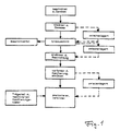
- Figure 1 the assembly of the finished part after lamination is not shown. This includes, for example, edge banding, i.e. the folding process.
- the procedure according to the invention gives the possibility of an automated, continuous production.
- storable intermediate products are created within the manufacturing process, so that internal aspects can be taken into account as well as the desired lot size when designing the process sequence. Both increase the economics of the process.
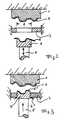
- the auxiliary tool 1 which receives the carrier part 2 positioned, is fixed in place, for example, in a press.
- the punching ring 3 is also arranged in a stationary manner below the auxiliary tool 1, with which the commercial lamination 6 made from the rough cut is cut to the finished size of the partial lamination (area A).
- the preformed fabric liner 6 is positively received by the punch 4.
- the contour of the stamping tool 4 is adapted to the portion of the carrier part to be laminated, so that it can simultaneously be used as a laminating stamp.
- the punch 4 is vertically movable with the aid of the stamp 4. In the position shown in FIG. 2, it takes up the lamination 6 preformed from the rough cut.
- the positioning of the carrier part 2 and the preformed lamination 6 can, if necessary, by a usual aids, which are not shown in the figures, are supported. For example, an application of negative pressure would be possible.
- the punch 4 has moved upwards with the help of the press ram 5 and has largely passed through the punch ring 3.
- the protrusion 6 ′′ of the rough blank 6 shears off, and the partial lamination 6 ′ is cut off.
- FIG. 4 shows the final stage of the partial lamination: the punching tool 4, in which the finished trim 6 ′ of the partial lamination is still located, has reached the auxiliary tool 1 with the positioned carrier part 2 with its adapted contour.
- the previously reactivated lamination adhesive is brought to crosslink with the reactive groups of the corresponding acrylic acid ester.
- the reactivation of the lamination adhesive presents no major difficulties. Because of the generally poor heat conduction of the carrier parts, the reactivation temperature of the adhesive layer can be maintained for a long time even when the carrier part is inserted into the auxiliary tool 1 and positioned there. This is especially true if support parts made of wood fiber materials are used. However, fiber materials of a different type as the base of the carrier parts or corresponding plastics are also not sufficiently thermally conductive to carry out the method according to the invention.
- FIGS. 2-4 show, for example, implementation of the partial lamination method, other geometries are possible. So it is above all possible to make the punching ring 3 vertically movable, and in this way to reduce the required master stroke in the press.
- Figure 5 shows a section of a partially laminated molded part.
- the carrier part 2 is provided with the comfortable groove 8.
- the groove follows the outline of the partial lamination.
- the fabric liner 7 has the angled part 7 'molded on and stabilized in shape. This bend plunges into the groove 8 of the carrier part and holds the plunge edge 9 'of the remaining lamination 9 in its position. This results in a clean butt joint 10 of visually appealing design and good mechanical stability, without high-frequency welding of the partial components of the overall lamination.
- the partial lamination 7 consists of a fluffy material resilient in the thickness direction, the lamination 9 is held securely in position by means of the plunge edge 9 '.
- the immersion edges 7 'and 9' can also be fixed with lamination adhesive, since corresponding pressure forces can be exerted.
- the dimensionally stable bend 7 'of the partial lamination is helpful; it can be used as it were as a "ruler” for the plunger 9' of the remaining lamination 9. It is particularly advantageous that the back coating of the partial liner 7, regardless of its textile character, reliably prevents fraying of the contour edges.
Claims (5)
- Procédé de contre-collage d'une pièce moulée, dans lequel une matière de contre-collage perméable à l'air est transformée en un matériau de contre-collage imperméable à l'air par application, au verso de la matière de contre-collage, d'une couche à déformation thermoplastique, du genre au cours duquel on fabrique une ébauche correspondant à la pièce de support préformée à contre-coller et on introduit cette ébauche chauffée et donc ramollie dans une moule non chauffé où elle est préformée et stabilisée thermiquement, après quoi la matière de contre-collage à forme stabilisée dont le moulage correspond à celui de la pièce moulée est liée de manière permanente à la pièce moulée à l'aide d'une colle de contre-collage par application d'une pression, caractérisé en ce qu'on utilise un revêtement au verso du tissu à contre-coller, qui peut être au moins partiellement réticulé avec la colle de contre-collage utilisée.
- Procédé selon la revendication 1, caractérisé par application au verso du tissu de contre-collage d'un mélange de 30 à 70 % en poids de résine acrylique (ester de l'acide acrylique) à auto-réticulation, le complément à 100 % en poids étant formé de résine acrylique thermoplastique, et par séchage de ce revêtement à des températures entre 140 et 150°C, ledit revêtement étant appliqué en quantité de 80 à 200 g/m³ (poids à sec), la mise en place de l'ébauche pré-formée sur la pièce de support revêtue d'une colle de contre-collage à base d'uréthanne, qui contient un excès d'isocyanate, et dans lequel au moins cette couche de colle a été chauffée, avant la mise en place, à une température de réactivation, et par la liaison du tissu de contre-collage préformé avec la pièce de support par réaction de l'excès d'isocyanate de la colle de contre-collage avec les groupes réactifs de l'ester d'acide acrylique pour former un joint de colle résistant à la chaleur et au moins partiellement réticulé par application d'une pression.
- Procédé selon les revendications 1 et 2, caractérisé en ce que l'ébauche préformée stabilisée du tissu de contre-collage est coupée, pour la réalisation d'un contre-collage partiel, sur le contour du contre-collage partiel avant sa mise en place et son collage avec la pièce de support.
- Procédé selon au moins l'une quelconque des revendications précédentes, caractérisé en ce que la découpe de l'ébauche préformée, la mise en place de la pièce de contre-collage partielle et la liaison sous pression de la pièce de contre-collage partielle sont effectués au cours d'une seule phase de travail.
- Procédé selon au moins l'une quelconque des revendications précédentes, caractérisé en ce qu'on utilise un tissu de contre-collage préformé découpé qui présente, au moins le long d'une partie de sa ligne de contour, une forme angulaire stabilisée, par laquelle il est introduit dans une rainure en forme de joint à recouvrement de la pièce de support en formant, dans cette rainure, avec un autre matériau de contre-collage de type et/ou de couleur différents, un joint bord à bord optiquement irréprochable.
Applications Claiming Priority (2)
| Application Number | Priority Date | Filing Date | Title |
|---|---|---|---|
| DE4105261 | 1991-02-20 | ||
| DE4105261A DE4105261C2 (de) | 1991-02-20 | 1991-02-20 | Verfahren zum Kaschieren von räumlich verformten Trägerteilen |
Publications (2)
| Publication Number | Publication Date |
|---|---|
| EP0500202A1 EP0500202A1 (fr) | 1992-08-26 |
| EP0500202B1 true EP0500202B1 (fr) | 1995-08-02 |
Family
ID=6425477
Family Applications (1)
| Application Number | Title | Priority Date | Filing Date |
|---|---|---|---|
| EP92250037A Expired - Lifetime EP0500202B1 (fr) | 1991-02-20 | 1992-02-20 | Procédé pour la fabrication d'un objet revêtu |
Country Status (3)
| Country | Link |
|---|---|
| EP (1) | EP0500202B1 (fr) |
| DE (2) | DE4105261C2 (fr) |
| ES (1) | ES2077347T3 (fr) |
Cited By (1)
| Publication number | Priority date | Publication date | Assignee | Title |
|---|---|---|---|---|
| US9314959B2 (en) | 2011-11-16 | 2016-04-19 | Lisa Draexlmaier Gmbh | Vehicle interior component with vacuum-laminated foam laminate |
Families Citing this family (14)
| Publication number | Priority date | Publication date | Assignee | Title |
|---|---|---|---|---|
| DE4300943C2 (de) * | 1993-01-15 | 1997-05-28 | Lignotock Gmbh | Vorrichtung mit elastomerem Überzug zum Kaschieren von Formteilen |
| DE4305189C2 (de) * | 1993-02-19 | 1995-11-02 | Huber Anton Systemtechnik Gmbh | Verfahren und Werkzeugeinrichtung für eine Vorrichtung zum Beziehen der Innenseitenflächen von Trägerteilen |
| US5410791A (en) * | 1993-07-01 | 1995-05-02 | General Electric Company | Fabrication chuck |
| DE69416460D1 (de) * | 1993-07-01 | 1999-03-25 | Gen Electric | Anschmiegendes Aufbringen von einer dünnen Membrane auf eine unregelmässig geformte Oberfläche |
| DE4327551A1 (de) * | 1993-08-13 | 1995-02-23 | Triag Ag Peter Sparber | Metallteil mit Kaschierung und Verfahren zur Herstellung eines solchen |
| DE4401903C1 (de) * | 1994-01-24 | 1994-12-01 | Peguform Werke Gmbh | Verfahren und Vorrichtung zum Kaschieren eines Bauteiles |
| DE4419994A1 (de) * | 1994-06-08 | 1995-12-14 | Pirchl Gerhard | Metallteil mit Kaschierung und Verfahren zur Herstellung eines solchen |
| ES2114387B1 (es) * | 1994-06-22 | 1999-06-01 | Fainsa Sa | Procedimiento de fabricacion de cuerpos laminares constitutivos de partes de asientos para vehiculos y similares. |
| ATE433511T1 (de) * | 1999-01-25 | 2009-06-15 | Hexion Specialty Chem Gmbh | Verfahren zur herstellung oberflächenveredelter faservliesformteile |
| DE10152892A1 (de) | 2001-10-26 | 2003-05-08 | Oce Printing Systems Gmbh | Verfahren und Vorrichtung zur Reinigung von Trägerelementen in Druckern oder Kopierern unter Anwendung von Magnetfeldern |
| DE10208524B4 (de) * | 2002-02-27 | 2004-07-08 | Johann Borgers Gmbh & Co. Kg | Verfahren zum Herstellen von Faservlies-Formteilen |
| DE10338812B4 (de) * | 2003-08-21 | 2012-05-31 | Daimler Ag | Hintergeschäumtes Bauteil und zugehöriges Herstellungsverfahren |
| DE102009031033B4 (de) * | 2009-06-30 | 2024-01-25 | Dr. Ing. H.C. F. Porsche Aktiengesellschaft | Verfahren zur Herstellung einer Verkleidung für ein Fahrzeuginnenteil |
| EP2744639A2 (fr) * | 2011-08-19 | 2014-06-25 | Johnson Controls Interiors GmbH & Co. KG | Procédé et dispositif pour réaliser le revêtement partiel d'un élément, notamment d'une pièce de véhicule |
Family Cites Families (7)
| Publication number | Priority date | Publication date | Assignee | Title |
|---|---|---|---|---|
| GB1225438A (fr) * | 1968-09-17 | 1971-03-17 | ||
| DE2365203B2 (de) * | 1973-12-31 | 1977-02-03 | Dynamit Nobel Ag, 5210 Troisdorf | Herstellen von mehrschichtigen bahnen, platten, formteilen |
| DE3128977A1 (de) * | 1981-07-22 | 1983-02-10 | Paul Kiefel Gmbh, 8228 Freilassing | Verfahren und vorrichtung zum herstellen von verbundkoerpern |
| DE3503192C1 (de) * | 1985-01-31 | 1986-09-18 | Johann Borgers Gmbh & Co Kg, 4290 Bocholt | Verfahren zur Herstellung eines Formteils aus einem durch Kunststoff verfestigten Faservlies und einem das Faservlies kaschierenden Bezugsstoff |
| DE3607647A1 (de) * | 1986-03-05 | 1987-09-17 | Kiss G H | Verfahren zum kaschieren von formteilen und vorrichtung zu seiner durchfuehrung |
| DE3626350A1 (de) * | 1986-08-04 | 1988-02-11 | Dynamit Nobel Ag | Innenraumverkleidung fuer ein kraftfahrzeug und verfahren zu ihrer herstellung |
| US4923539A (en) * | 1988-09-16 | 1990-05-08 | Stanztechnik Gmbh R+S | Method and apparatus for manufacturing trim panels including several trim components |
-
1991
- 1991-02-20 DE DE4105261A patent/DE4105261C2/de not_active Expired - Fee Related
-
1992
- 1992-02-20 ES ES92250037T patent/ES2077347T3/es not_active Expired - Lifetime
- 1992-02-20 DE DE59203066T patent/DE59203066D1/de not_active Expired - Lifetime
- 1992-02-20 EP EP92250037A patent/EP0500202B1/fr not_active Expired - Lifetime
Cited By (1)
| Publication number | Priority date | Publication date | Assignee | Title |
|---|---|---|---|---|
| US9314959B2 (en) | 2011-11-16 | 2016-04-19 | Lisa Draexlmaier Gmbh | Vehicle interior component with vacuum-laminated foam laminate |
Also Published As
| Publication number | Publication date |
|---|---|
| DE4105261C2 (de) | 1994-03-31 |
| DE4105261A1 (de) | 1992-08-27 |
| EP0500202A1 (fr) | 1992-08-26 |
| DE59203066D1 (de) | 1995-09-07 |
| ES2077347T3 (es) | 1995-11-16 |
Similar Documents
| Publication | Publication Date | Title |
|---|---|---|
| EP0500202B1 (fr) | Procédé pour la fabrication d'un objet revêtu | |
| EP2279915B1 (fr) | Composants d'équipement intérieur à plusieurs couleurs | |
| EP1646492B1 (fr) | Elements de garniture interieure pour vehicules automobiles presentant un profil de surface defini | |
| DE10033232C2 (de) | Fahrzeugdachteil mit einer Kunststoff-Außenhaut, Verfahren und Vorrichtung zur Herstellung desselben | |
| DE4419908C2 (de) | Verfahren zum Herstellen eines kaschierten Formteiles | |
| DE4007829A1 (de) | Verfahren zum herstellen einer verkleidungsplatte | |
| EP0657265B1 (fr) | Procédé de fabrication d'éléments plats revêtus utilisant des préformes en forme de grille | |
| DE60113767T2 (de) | Verfahren zur Herstellung von Kraftfahrzeuglenkrädern, insbesondere Holzlenkräder mit einer Hülle aus hochwertigem Material, und durch ein solches Verfahren hergestellte Lenkräder | |
| EP0410553B1 (fr) | Procédé pour fabriquer des objets formés et revêtus | |
| EP1238785B1 (fr) | Procédé pour fabriquer un article profilé en forme de coque et moule utilisable pour celui-ci | |
| EP0247344A2 (fr) | Procédé de fabrication d'articles multi-couches | |
| DE3537997A1 (de) | Verfahren zur herstellung eines formteiles mit stoffverkleidung | |
| DE4305189C2 (de) | Verfahren und Werkzeugeinrichtung für eine Vorrichtung zum Beziehen der Innenseitenflächen von Trägerteilen | |
| DE19500233C2 (de) | Verkleidungsteil für den Innenausbau insbesondere von Kraftfahrzeugen und Verfahren zur Herstellung eines Verkleidungsteils | |
| EP2024164B1 (fr) | Procédé et dispositif de fabrication d'une pièce moulée contrecollée | |
| DE10249372A1 (de) | Lenkrad und Herstellungsverfahren dafür | |
| DE102005045794B4 (de) | Verfahren zur Herstellung einer mehrschichtigen Unterbodenverkleidung für Kraftfahrzeuge | |
| DE3033494C2 (de) | Vorrichtung zum Herstellen von Formteilen aus einer Trägerschicht und einer dekorativen Oberflächenschicht und Verfahren zum Betreiben der Vorrichtung | |
| DE102011014513A1 (de) | Herstellungsverfahren für Formteile mit unterschiedlichen Oberflächenmaterialien | |
| DE102015225363A1 (de) | Verfahren zur Herstellung eines Zierelements für ein Fahrzeug | |
| DE102005011474B4 (de) | Verfahren zur Herstellung von Kunststoffformteilen mit Hinterschneidungen unter Verwendung eingelegter Füllstücke | |
| DE102019122385A1 (de) | Dachhimmel und verfahren zu dessen herstellung | |
| DE19634840A1 (de) | Verfahren und Vorrichtung zur flächenhaften Aufbringung von Dekormaterial zur Verkleidung eines Formteils | |
| DE10252603A1 (de) | Verfahren zur Herstellung eines Dachhimmels mit wenigstens einem Energieabsorptionselement und entsprechender Dachhimmel | |
| DE102018131722A1 (de) | Formwerkzeug zum Fügen von Verkleidungsteilen mit flächigen Dekormaterialien und ein entsprechendes Verfahren |
Legal Events
| Date | Code | Title | Description |
|---|---|---|---|
| PUAI | Public reference made under article 153(3) epc to a published international application that has entered the european phase |
Free format text: ORIGINAL CODE: 0009012 |
|
| AK | Designated contracting states |
Kind code of ref document: A1 Designated state(s): DE ES FR GB IT |
|
| 17P | Request for examination filed |
Effective date: 19921020 |
|
| 17Q | First examination report despatched |
Effective date: 19940425 |
|
| GRAA | (expected) grant |
Free format text: ORIGINAL CODE: 0009210 |
|
| AK | Designated contracting states |
Kind code of ref document: B1 Designated state(s): DE ES FR GB IT |
|
| REF | Corresponds to: |
Ref document number: 59203066 Country of ref document: DE Date of ref document: 19950907 |
|
| GBT | Gb: translation of ep patent filed (gb section 77(6)(a)/1977) |
Effective date: 19950913 |
|
| ITF | It: translation for a ep patent filed |
Owner name: DR. ING. A. RACHELI & C. |
|
| REG | Reference to a national code |
Ref country code: ES Ref legal event code: FG2A Ref document number: 2077347 Country of ref document: ES Kind code of ref document: T3 |
|
| ET | Fr: translation filed | ||
| PLBE | No opposition filed within time limit |
Free format text: ORIGINAL CODE: 0009261 |
|
| STAA | Information on the status of an ep patent application or granted ep patent |
Free format text: STATUS: NO OPPOSITION FILED WITHIN TIME LIMIT |
|
| 26N | No opposition filed | ||
| REG | Reference to a national code |
Ref country code: GB Ref legal event code: IF02 |
|
| PGFP | Annual fee paid to national office [announced via postgrant information from national office to epo] |
Ref country code: GB Payment date: 20050307 Year of fee payment: 14 |
|
| PGFP | Annual fee paid to national office [announced via postgrant information from national office to epo] |
Ref country code: FR Payment date: 20050309 Year of fee payment: 14 |
|
| PGFP | Annual fee paid to national office [announced via postgrant information from national office to epo] |
Ref country code: ES Payment date: 20050316 Year of fee payment: 14 |
|
| PG25 | Lapsed in a contracting state [announced via postgrant information from national office to epo] |
Ref country code: GB Free format text: LAPSE BECAUSE OF NON-PAYMENT OF DUE FEES Effective date: 20060220 |
|
| PG25 | Lapsed in a contracting state [announced via postgrant information from national office to epo] |
Ref country code: ES Free format text: LAPSE BECAUSE OF NON-PAYMENT OF DUE FEES Effective date: 20060221 |
|
| PGFP | Annual fee paid to national office [announced via postgrant information from national office to epo] |
Ref country code: IT Payment date: 20060228 Year of fee payment: 15 |
|
| GBPC | Gb: european patent ceased through non-payment of renewal fee |
Effective date: 20060220 |
|
| REG | Reference to a national code |
Ref country code: FR Ref legal event code: ST Effective date: 20061031 |
|
| REG | Reference to a national code |
Ref country code: ES Ref legal event code: FD2A Effective date: 20060221 |
|
| PG25 | Lapsed in a contracting state [announced via postgrant information from national office to epo] |
Ref country code: FR Free format text: LAPSE BECAUSE OF NON-PAYMENT OF DUE FEES Effective date: 20060228 |
|
| PG25 | Lapsed in a contracting state [announced via postgrant information from national office to epo] |
Ref country code: IT Free format text: LAPSE BECAUSE OF NON-PAYMENT OF DUE FEES Effective date: 20070220 |
|
| PGFP | Annual fee paid to national office [announced via postgrant information from national office to epo] |
Ref country code: DE Payment date: 20110315 Year of fee payment: 20 |
|
| REG | Reference to a national code |
Ref country code: DE Ref legal event code: R071 Ref document number: 59203066 Country of ref document: DE |
|
| REG | Reference to a national code |
Ref country code: DE Ref legal event code: R071 Ref document number: 59203066 Country of ref document: DE |
|
| PG25 | Lapsed in a contracting state [announced via postgrant information from national office to epo] |
Ref country code: DE Free format text: LAPSE BECAUSE OF EXPIRATION OF PROTECTION Effective date: 20120221 |