EP0499698B1 - Lüfterantrieb mit Flüssigkeitsreibungskupplung - Google Patents
Lüfterantrieb mit Flüssigkeitsreibungskupplung Download PDFInfo
- Publication number
- EP0499698B1 EP0499698B1 EP91120254A EP91120254A EP0499698B1 EP 0499698 B1 EP0499698 B1 EP 0499698B1 EP 91120254 A EP91120254 A EP 91120254A EP 91120254 A EP91120254 A EP 91120254A EP 0499698 B1 EP0499698 B1 EP 0499698B1
- Authority
- EP
- European Patent Office
- Prior art keywords
- fan
- drive
- coupling
- hub
- pulley
- Prior art date
- Legal status (The legal status is an assumption and is not a legal conclusion. Google has not performed a legal analysis and makes no representation as to the accuracy of the status listed.)
- Expired - Lifetime
Links
Images


Classifications
-
- F—MECHANICAL ENGINEERING; LIGHTING; HEATING; WEAPONS; BLASTING
- F04—POSITIVE - DISPLACEMENT MACHINES FOR LIQUIDS; PUMPS FOR LIQUIDS OR ELASTIC FLUIDS
- F04D—NON-POSITIVE-DISPLACEMENT PUMPS
- F04D25/00—Pumping installations or systems
- F04D25/02—Units comprising pumps and their driving means
- F04D25/028—Units comprising pumps and their driving means the driving means being a planetary gear
-
- F—MECHANICAL ENGINEERING; LIGHTING; HEATING; WEAPONS; BLASTING
- F01—MACHINES OR ENGINES IN GENERAL; ENGINE PLANTS IN GENERAL; STEAM ENGINES
- F01P—COOLING OF MACHINES OR ENGINES IN GENERAL; COOLING OF INTERNAL-COMBUSTION ENGINES
- F01P5/00—Pumping cooling-air or liquid coolants
- F01P5/02—Pumping cooling-air; Arrangements of cooling-air pumps, e.g. fans or blowers
- F01P5/04—Pump-driving arrangements
-
- F—MECHANICAL ENGINEERING; LIGHTING; HEATING; WEAPONS; BLASTING
- F01—MACHINES OR ENGINES IN GENERAL; ENGINE PLANTS IN GENERAL; STEAM ENGINES
- F01P—COOLING OF MACHINES OR ENGINES IN GENERAL; COOLING OF INTERNAL-COMBUSTION ENGINES
- F01P7/00—Controlling of coolant flow
- F01P7/02—Controlling of coolant flow the coolant being cooling-air
- F01P7/04—Controlling of coolant flow the coolant being cooling-air by varying pump speed, e.g. by changing pump-drive gear ratio
- F01P7/042—Controlling of coolant flow the coolant being cooling-air by varying pump speed, e.g. by changing pump-drive gear ratio using fluid couplings
-
- F—MECHANICAL ENGINEERING; LIGHTING; HEATING; WEAPONS; BLASTING
- F01—MACHINES OR ENGINES IN GENERAL; ENGINE PLANTS IN GENERAL; STEAM ENGINES
- F01P—COOLING OF MACHINES OR ENGINES IN GENERAL; COOLING OF INTERNAL-COMBUSTION ENGINES
- F01P7/00—Controlling of coolant flow
- F01P7/02—Controlling of coolant flow the coolant being cooling-air
- F01P7/04—Controlling of coolant flow the coolant being cooling-air by varying pump speed, e.g. by changing pump-drive gear ratio
- F01P7/046—Controlling of coolant flow the coolant being cooling-air by varying pump speed, e.g. by changing pump-drive gear ratio using mechanical drives
-
- F—MECHANICAL ENGINEERING; LIGHTING; HEATING; WEAPONS; BLASTING
- F04—POSITIVE - DISPLACEMENT MACHINES FOR LIQUIDS; PUMPS FOR LIQUIDS OR ELASTIC FLUIDS
- F04D—NON-POSITIVE-DISPLACEMENT PUMPS
- F04D19/00—Axial-flow pumps
- F04D19/02—Multi-stage pumps
- F04D19/024—Multi-stage pumps with contrarotating parts
-
- F—MECHANICAL ENGINEERING; LIGHTING; HEATING; WEAPONS; BLASTING
- F04—POSITIVE - DISPLACEMENT MACHINES FOR LIQUIDS; PUMPS FOR LIQUIDS OR ELASTIC FLUIDS
- F04D—NON-POSITIVE-DISPLACEMENT PUMPS
- F04D25/00—Pumping installations or systems
- F04D25/02—Units comprising pumps and their driving means
- F04D25/022—Units comprising pumps and their driving means comprising a yielding coupling, e.g. hydraulic
-
- F—MECHANICAL ENGINEERING; LIGHTING; HEATING; WEAPONS; BLASTING
- F04—POSITIVE - DISPLACEMENT MACHINES FOR LIQUIDS; PUMPS FOR LIQUIDS OR ELASTIC FLUIDS
- F04D—NON-POSITIVE-DISPLACEMENT PUMPS
- F04D25/00—Pumping installations or systems
- F04D25/02—Units comprising pumps and their driving means
- F04D25/026—Units comprising pumps and their driving means with a magnetic coupling
-
- F—MECHANICAL ENGINEERING; LIGHTING; HEATING; WEAPONS; BLASTING
- F16—ENGINEERING ELEMENTS AND UNITS; GENERAL MEASURES FOR PRODUCING AND MAINTAINING EFFECTIVE FUNCTIONING OF MACHINES OR INSTALLATIONS; THERMAL INSULATION IN GENERAL
- F16D—COUPLINGS FOR TRANSMITTING ROTATION; CLUTCHES; BRAKES
- F16D35/00—Fluid clutches in which the clutching is predominantly obtained by fluid adhesion
- F16D35/02—Fluid clutches in which the clutching is predominantly obtained by fluid adhesion with rotary working chambers and rotary reservoirs, e.g. in one coupling part
- F16D35/021—Fluid clutches in which the clutching is predominantly obtained by fluid adhesion with rotary working chambers and rotary reservoirs, e.g. in one coupling part actuated by valves
- F16D35/022—Fluid clutches in which the clutching is predominantly obtained by fluid adhesion with rotary working chambers and rotary reservoirs, e.g. in one coupling part actuated by valves the valve being actuated by a bimetallic strip
Definitions
- the invention relates to a fan drive with fluid friction clutch according to the preamble of claim 1 - such fan drives are known, e.g. by DE-C 28 14 608.
- the invention is therefore based on the object of providing a fan drive which can provide an increased air throughput, in particular at low engine speeds.
- This object is achieved by the characterizing features in connection with those of the preamble of claim 1.
- the second fan arranged behind the first fan, the so-called counter-rotor can therefore be switched on as needed, ie in particular at low engine speeds or depending on other parameters, ie it then runs at the opposite peripheral speed as the first Fan around and thus ensures an increased air flow without having to increase the engine speed.
- the fan drive according to the invention thus makes it possible to provide a motor vehicle whose engine is running at idling speed or at a relatively low speed with sufficient cooling air and also to cool the condenser sufficiently without the need for additional electric fans.
- the counter-rotor is mounted coaxially with its hub on the hub of the fluid friction clutch, which results in an axially particularly short construction.
- the counter-rotor can be switched on via a gear transmission, whereby a defined speed ratio between the two fans is ensured.
- this gear transmission is designed as a planetary gear, which allows a space-saving and coaxially compact design and allows a step-down and translation, which is possible by single or double toothed planet gears.
- the second clutch is designed as an electromagnetic brake, i.e. the web of the planetary gear has a disk surface which serves as a braking surface and can be fixed via the electromagnetic brake.
- the transmission is designed as a belt drive, preferably as a V-belt drive or toothed belt drive, wherein one belt drive each is connected to the first and the second fan and both belt drives can be rigidly connected to one another via a coupling.
- a belt drive is relatively light and is simple, ie economical to manufacture.
- the clutch is arranged within a pulley, so that thereby hardly any additional space is required - at the same time both belt drives can be easily coupled.
- pulleys are provided, in particular a pulley arranged outside the first belt drive, which ensures a reversal of the direction of rotation from the first to the second belt drive, because the first belt drive drives this pulley with its outside.
- a toothed belt drive is particularly suitable for this type of reversal of the direction of rotation due to the relatively small wrap angle.
- a further fluid friction clutch is provided in the hub area of the second fan, which is not regulated by external parameters, but regulates itself by torque limitation.
- This type of fluid friction clutch is known per se; here it has the advantage that the counter-rotor regulates itself automatically at high fan speeds and thus avoids noise peaks.
- a known fluid friction clutch 3 is shown schematically, which carries on its circumference an axial fan 1 with known axial blading.
- This fluid friction clutch has, in a known manner, a storage chamber 4 and a working chamber 5, which are separated from one another by a partition 6, but are connected to one another via a valve bore 8, which is controlled by a valve lever 7.
- the valve lever 7 is controlled via a bimetal 9 arranged on the outside of the clutch via a switching pin 10.
- a drive pulley 11 is arranged in the working chamber 5 and is connected to the drive shaft 12.
- the fluid friction clutch is filled with a viscous medium, which circulates between the storage and working chamber and thus determines the transmissible torque or the speed of the fan 1.
- the housing of the clutch 3 is rotatably mounted with its hub 13 on the drive shaft 12 via a ball bearing 14.
- a further ball bearing 15 is arranged on the outside of the hub 13 and carries a second axial fan 2 via a hub 16, the so-called counter-rotor.
- the blading of this counter-rotor 2 is arranged in the opposite direction to that of the first fan 1, so that there is a deflection (reaction) of the axial flow in a manner known per se.
- Fan 1 and counter-rotor 2 can be connected to one another via the clutch 21 and a planetary gear, which will be described below.
- the hub 13 of the clutch housing 3 carries an internal toothing 17 provided with external teeth, which engages with a set of planet gears 19 which are carried by the planet carrier 20.
- planet gears 19 are in engagement with an external sun 18 with internal teeth, which is arranged in the hub region 16 of the counter-rotor 2.
- the planet carrier 20, the transmission technology is designed as a so-called web, is mounted coaxially to the drive shaft 12 via a further ball bearing 22 and can - if the counter-rotor is to be switched on - fixed via the electromagnetic clutch or brake 21.
- the planetary or epicyclic gearbox has become a so-called stationary gearbox, with the result that the inner sun 17 drives via the planet gears 19 onto the outer sun 18 and thus entrains the counter-rotor 2 in the opposite direction and at approximately the same speed.
- the mode of operation of this fan drive is therefore as follows: If only a "normal" air flow rate for the cooler or the cooling module (including the condenser, charge air cooler, etc.) is required, which can be made available by the operating speed of the internal combustion engine, the counter-rotor 2 uncoupled, ie there is no fixed speed ratio to the first fan 1, but only loosely circulates in the axial wake flow of fan 1. This does not result in loss of throughput in cooling air. However, if more cooling air is required, especially at low engine speed, the Counter rotor 2 switched on via the clutch 21 by fixing the web shaft 20. It is then driven at the speed n 1 of the first fan 1 and driven off in the opposite direction by the planetary gear and at approximately the same speed n 2. This results in a considerable pressure increase in Regarding the entry of the air tflow at the first fan 1 and the outlet at the counter rotor 2, ie an increased air throughput.
- the planet gears 19 can also (which is not shown) be designed in two stages, ie have two toothings, the one combs with the inside sun and the other with the outside sun. This enables quick translation.
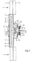
- FIG. 2 and 3 show a further exemplary embodiment of the invention, specifically with a belt drive, the same reference numbers being used for the clutch, the first and the second fan, in part with the same or functionally identical parts.
- Fig. 2 shows an axial section through the fan drive and
- Fig. 3 is a view according to section III-III.
- the first fan 1 is thus in turn arranged on the fluid friction clutch 3, which is driven by the engine via a drive shaft 12, ie via a belt drive 23.
- the clutch 3 is mounted coaxially to the drive shaft 12 by means of its hub 13 via a ball bearing 14, and the counter-rotor 2 is likewise mounted coaxially with respect to the drive shaft 12 with its hub 16 and a ball bearing 15.
- the hub 13 of the clutch 3 is axially extended somewhat further into the plane of a first belt drive 24, while the hub 16 of the counter-rotating mechanism 2 is axially offset into the plane of a second belt drive 25.
- a first pulley 26 and at the end of the hub 16 a further pulley 31 is arranged in a rotationally fixed manner.
- the first pulley 26 connected to the first fan 1 drives a pulley 29 via a belt drive 24 and a deflection roller 27.
- the further pulley 31, which is connected to the counter-rotor 2 is driven by the pulley 28 via the second belt drive 25.
- the two belt drives 24 and 25 are axially offset from one another and separated.
- both belt drives 24 and 25 can be brought into engagement with one another, with the special belt arrangement, as shown in FIG. 3, a reversal of the direction of rotation 24 'to that with the Required angle wrapped pulley 29, in which the stationary magnetic coupling 30 is located, this is clearly shown by the arrows in Fig. 3.
- the mode of operation is the same as that for the exemplary embodiment in FIG. 1, ie either the counter-rotor 2 runs loosely in the non-connected state, or it is connected by the clutch 30 and runs in opposite directions and at approximately the same speed (n 2 ) to the first Fan (n 1 ) with around, which leads to the pressure rise already mentioned, especially at low drive speeds.
- Fig. 4 shows an advantageous development of the invention, in such a way that the counter-rotor 2 is driven by a torque-limited fluid friction clutch.
- This development corresponds to the exemplary embodiment in FIG. 1, where the counter-rotor 2 is driven rigidly by the outside sun 18.
- the outside sun is connected to a drive disk 33, which rotates in a working chamber 32 of a fluid friction clutch, while this working chamber 32, which simultaneously forms the clutch housing, is mounted on the hub 16 via a hub region 35 and a further ball bearing 34.
- the working chamber 32 is filled in a known manner with a viscous medium, so that a certain slip occurs between the drive disk 33 and the clutch housing 32.
- this clutch regulates itself, that is, the speed n 2 of the counter-rotor does not increase further, because the torque received by the fan is in equilibrium with the maximum transmissible torque in the fluid friction clutch is.
Description
- Die Erfindung bezieht sich auf einen Lüfterantrieb mit Flüssigkeitsreibungskupplung entsprechend dem Oberbegriff des Patentanspruches 1 - derartige Lüfterantriebe sind bekannt, z.B. durch die DE-C 28 14 608.
- Bei derartigen Lüfterantrieben besteht der Nachteil, daß diese Lüfter bei niedrigen Motordrehzahlen zu wenig Luft fördern, obwohl in derartigen Betriebssituationen häufig mehr Luft zur Kühlung benötigt wird, insbesondere, wenn zusätzlich zum Kühlmittelkühler noch ein Kondensator einer Klimaanlage oder ein Ölkühler mit Kühlluft zu versorgen ist.
- Der Erfindung liegt daher die Aufgabe zugrunde, einen Lüfterantrieb zu schaffen, der insbesondere bei niedrigen Motordrehzahlen einen erhöhten Luftdurchsatz zur Verfügung stellen kann. Diese Aufgabe wird durch die kennzeichnenden Merkmale in Verbindung mit denen des Oberbegriffes des Patentanspruches 1 gelöst. Der hinter dem ersten Lüfter angeordnete zweite Lüfter, der sog. Gegenläufer, kann also bedarfsweise, d.h. insbesondere bei niedrigen Motordrehzahlen oder in Abhängigkeit von anderen Parametern zugeschaltet werden, d.h. er läuft dann mit entgegengesetzter Umfangsgeschwindigkeit wie der erste Lüfter um und sorgt damit für einen erhöhten Luftdurchsatz, ohne daß die Motordrehzahl angehoben werden muß. Dies ist ein erheblicher Vorteil, gerade bei Kraftfahrzeugen, bei welchen die Motordrehzahl nicht beliebig variiert werden kann. Durch den erfindungsgemäßen Lüfterantrieb ist es somit möglich, ein Kraftfahrzeug, dessen Motor mit Leerlaufdrehzahl oder mit relativ niedriger Drehzahl umläuft, hinreichend mit Kühllüft zu versorgen und dabei auch den Kondensator hinreichend zu kühlen, ohne daß zusätzliche Elektrolüfter benötigt werden.
- Gemäß Anspruch 2 ergibt sich ein besonders hoher Druckgewinn, wenn der Gegenläufer mit etwa gleicher Drehzahl wie der des ersten Lüfters umläuft, wobei das Übersetzungsverhältnis in Abhängigkeit von der Geräuschbildung gewählt werden kann.
- Gemäß Anspruch 3 ist der Gegenläufer mit seiner Nabe auf der Nabe der Flüssigkeitsreibungskupplung koaxial gelagert, was eine axial besonders kurze Bauweise ergibt.
- Gemäß Anspruch 4 ist der Gegenläufer über ein Zahnradgetriebe zuschaltbar, wodurch ein definiertes Drehzahlverhältnis zwischen beiden Lüftern gewährleistet ist.
- Gemäß Anspruch 5 ist dieses Zahnradgetriebe als Planetengetriebe ausgebildet, was eine raumsparende und koaxial gedrängte Bauweise ermöglicht und eine Unter- und Übersetzung zuläßt, welche durch einfach oder doppelt verzahnte Planetenräder möglich wird.
- Gemäß Anspruch 6 ist die zweite Kupplung als Elektromagnetbremse ausgebildet, d.h. der Steg des Planetengetriebes weist eine Scheibenfläche auf, die als Bremsfläche dient und über die Elektromagnetbremse festgesetzt werden kann.
- Gemäß Anspruch 7 ist das Getriebe als Riementrieb ausgebildet, und zwar vorzugsweise als Keilriementrieb oder Zahnriementrieb, wobei je ein Riementrieb mit dem ersten und dem zweiten Lüfter verbunden sind und beide Riementriebe über eine Kupplung starr miteinander verbunden werden können. Ein solcher Riementrieb baut relativ leicht und ist einfach, d.h. wirtschaftlich herstellbar.
- Gemäß Anspruch Anspruch 8 ist die Schaltkupplung innerhalb einer Riemenscheibe angeordnet, so daß hierdurch kaum zusätzlicher Bauraum benötigt wird - gleichzeitig können beide Riementriebe einfach gekuppelt werden.
- Gemäß Anspruch 9 sind weitere Riemenscheiben vorgesehen, insbesondere eine außerhalb des ersten Riementriebes angeordnete Riemenscheibe, die für eine Drehrichtungsumkehr vom ersten auf den zweiten Riementrieb sorgt, weil der erste Riementrieb diese Riemenscheibe mit seiner Außenseite antreibt. Für diese Art der Drehrichtungsumkehr ist infolge des relativ geringen Umschlingungswinkels ein Zahnriementrieb besonders geeignet.
- Gemäß Anspruch 10 ist im Nabenbereich des zweiten Lüfters eine weitere Flüssigkeitsreibungskupplung vorgesehen, die nicht durch äußere Parameter geregelt ist, sondern sich selbst durch Drehmomentbegrenzung abregelt. Diese Art von Flüssigkeitsreibungskupplung ist an sich bekannt; sie hat hier den Vorteil, daß sich der Gegenläufer bei hohen Lüfterdrehzahlen selbständig abregelt und damit Geräuschspitzen vermeidet.
- Zwei Ausführungsbeispiele der Erfindung sind in der Zeichnung dargestellt und werden im folgenden näher beschrieben:
- Fig. 1
- zeigt ein erstes Ausführungsbeispiel mit Planetengetriebe,
- Fig. 2
- zeigt ein zweites Ausführungsbeispiel mit Keilriementrieb,
- Fig. 3
- einen Schnitt gemäß Linie III - III in Fig. 2, und
- Fig. 4
- zeigt den Gegenläufer, angetrieben von einer weiteren Flüssigkeitsreibungskupplung.
- In Fig. 1 ist schematisch eine an sich bekannte Flüssigkeitsreibungskupplung 3 dargestellt, die auf ihrem Umfang einen Axiallüfter 1 mit an sich bekannter Axialbeschaufelung trägt. Diese Flüssigkeitsreibungskupplung weist in bekannter Art eine Vorratskammer 4 und eine Arbeitskammer 5 auf, die durch eine Trennwand 6 voneiander abgeteilt sind, aber über eine Ventilbohrung 8, die von einem Ventilhebel 7 gesteuert wird, miteinander in Verbindung stehen. Hier ist der Ventilhebel 7 über ein auf der Kupplungsaußenseite angeordnetes Bimetall 9 über einen Schaltstift 10 gesteuert. In der Arbeitskammer 5 ist eine Antriebsscheibe 11 angeordnet, die mit der Antriebswelle 12 verbunden ist. Die Flüssigkeitsreibungskupplung ist mit einem viskosen Medium gefüllt, welches zwischen Vorrats- und Arbeitskammer zirkuliert und damit das übertragbare Drehmoment bzw. die Drehzahl des Lüfters 1 bestimmt. Das Gehäuse der Kupplung 3 ist mit seiner Nabe 13 über ein Kugellager 14 auf der Antriebswelle 12 drehbar gelagert. Auf der Außenseite der Nabe 13 ist ein weiteres Kugellager 15 angeordnet, welches über eine Nabe 16 einen zweiten Axiallüfter 2 trägt, den sog. Gegenläufer. Die Beschaufelung dieses Gegenläufers 2 ist in entgegengesetzter Richtung wie die des ersten Lüfters 1 angeordnet, so daß sich in an sich bekannter Weise eine Umlenkung (Reaktion) der Axialströmung ergibt. Lüfter 1 und Gegenläufer 2 können über die Kupplung 21 und ein Planetengetriebe, welches im folgenden beschrieben wird, miteinander verbunden werden. Die Nabe 13 des Kupplungsgehäuses 3 trägt eine mit Außenverzahnung versehene Innensonne 17, die mit einem Satz Planetenräder 19 in Eingriff steht, welche von dem Planetenträger 20 getragen werden. Diese Planetenräder 19 stehen andererseits in Eingriff mit einer Außensonne 18 mit Innenverzahnung, welche im Nabenbereich 16 des Gegenläufers 2 angeordnet ist. Der Planetenträger 20, der getriebetechnisch als sog. Steg ausgebildet ist, ist über ein weiteres Kugellager 22 koaxial zur Antriebswelle 12 gelagert und kann - wenn nämlich der Gegenläufer zugeschaltet werden soll - über die Elektromagnetkupplung bzw. -Bremse 21 festgesetzt werden. Dann ist nämlich aus dem Planeten- oder Umlaufgetriebe ein sog. Standgetriebe geworden, was zur Folge hat, daß die Innensonne 17 über die Planetenräder 19 auf die Außensonne 18 treibt und somit den Gegenläufer 2 in entgegengesetzter Richtung und mit etwa gleicher Drehzahl mitnimmt. Soll der Gegenläufer 2 nicht mitlaufen, so wird die Kupplung 21 gelöst, und der Steg bzw. Planetenträger 20 läuft mit seinen Planetenrädern 19 um. Dabei stellt sich in bekannter Weise ein Momentengleichgewicht zwischen antreibender Innensonne 17 und abgetriebener Außensonne 18 ein, was weiterhin zur Folge hat, daß der Gegenläufer 2 lediglich im "Windmühlenbetrieb'' mittrudelt.
- Die Funktionsweise dieses Lüfterantriebes ist also die folgende: Wird lediglich ein "normaler'' Luftdurchsatz für den Kühler bzw. das Kühlmodul (einschließlich Kondensator, Ladeluftkühler etc.) gefordert, der durch die Betriebsdrehzahl der Brennkraftmaschine zur Verfügung gestellt werden kann, ist der Gegenläufer 2 abgekuppelt, d.h. er steht in keinem festen Drehzahlverhältnis zum ersten Lüfter 1, sondern läuft lediglich in der axialen Nachlaufströmung des Lüfters 1 lose mit um. Dadurch werden keine Durchsatzverluste an Kühlluft bewirkt. Wird jedoch mehr Kühlluft, insbesondere bei niedriger Motordrehzahl benötigt, so wird der Gegenläufer 2 über die Kupplung 21 durch Festsetzen der Stegwelle 20 zugeschaltet. Er wird dann also mit der Drehzahl n1 des ersten Lüfters 1 angetrieben und durch das Planetengetriebe in entgegengesetzter Richtung und mit etwa gleicher Drehzahl n2 abgetrieben. Dadurch ergibt sich eine erhebliche Drucksteigerung in Bezug auf den Eintritt der Luftströmung am ersten Lüfter 1 und den Austritt am Gegenläufer 2, d.h. ein erhöhter Luftdurchsatz.
- Die Planetenräder 19 können auch (was nicht dargestellt ist) zweistufig ausgebildet sein, d.h. zwei Verzahnungen aufweisen, wobei die eine mit der Innensonne und die andere mit der Außensonne kämmt. Damit wird eine Übersetzung ins Schnelle erreicht.
- In den Fig. 2 und 3 ist ein weiteres Ausführungsbeispiel der Erfindung, und zwar mit einem Riementrieb dargestellt, wobei für die Kupplung, den ersten und den zweiten Lüfter zum Teil bei gleichen bzw. funktionsgleichen Teilen dieselben Bezugsziffern verwendet wurden. Fig. 2 zeigt einen Axialschnitt durch den Lüfterantrieb und Fig. 3 eine Ansicht gemäß Schnitt III -III. Der erste Lüfter 1 ist also wiederum auf der Flüssigkeitsreibungskupplung 3 angeordnet, die über eine Antriebswelle 12 vom Motor her, d.h. über einen Riementrieb 23 angetrieben wird. Die Kupplung 3 ist mittels ihrer Nabe 13 über ein Kugellager 14 koaxial zur Antriebswelle 12 gelagert, und der Gegenläufer 2 ist mit seiner Nabe 16 und ein Kugellager 15 ebenfalls koaxial gegenüber der Antriebswelle 12 gelagert. Die Nabe 13 der Kupplung 3 ist dabei axial etwas weiter in die Ebene eines ersten Riementriebes 24 hinausgeführt, während die Nabe 16 des Gegenläufers 2 axial versetzt bis in die Ebene eines zweiten Riementriebes 25 hinausgezogen ist. Am Ende der Nabe 13 ist eine erste Riemenscheibe 26 und am Ende der Nabe 16 eine weitere Riemenscheibe 31 drehfest angeordnet. Die mit dem ersten Lüfter 1 verbundene erste Riemenscheibe 26 treibt über einen Riementrieb 24 und eine Umlenkrolle 27 eine Riemenscheibe 29. Die weitere Riemenscheibe 31, die mit dem Gegenläufer 2 verbunden ist, wird über den zweiten Riementrieb 25 von der Riemenscheibe 28 angetrieben. Insofern sind die beiden Riementriebe 24 und 25 axial gegeneinander versetzt und getrennt. Über eine koaxial zur Riemenscheibe 28 angeordnete Magnetkupplung 30 in der Riemenscheibe 29 können jedoch beide Riementriebe 24 und 25 miteinander in Eingriff gebracht werden, wobei aufgrund der speziellen Riemenanordnung, wie sie aus Fig. 3 hervorgeht, eine Drehrichtungsumkehr vom Zugtrum 24' auf die mit dem erforderlichen Winkel umschlungene Riemenscheibe 29, in welcher sich die ortsfeste Magnetkupplung 30 befindet, erfolgt - dies geht auch aus den Pfeilen in Fig. 3 deutlich hervor.
- Die Funktionsweise ist dieselbe, wie für das Ausführungsbeispiel in Fig. 1 ausgeführt, d.h. entweder läuft der Gegenläufer 2 im nicht zugeschalteten Zustand lose mit, oder er ist durch die Kupplung 30 zugeschaltet und läuft gegensinnig und mit etwa gleicher Drehzahl (n2) zum ersten Lüfter (n1) mit um, was zu dem bereits erwähnten Druckanstieg, insbesondere bei niedrigen Antriebsdrehzahlen führt.
- Fig. 4 zeigt eine vorteilhafte Weiterbildung der Erfindung, und zwar in der Weise, daß der Gegenläufer 2 durch eine drehmomentbegrenzte Flüssigkeitsreibungskupplung angetrieben wird. Diese Weiterbildung entspricht dem Ausführungsbeispiel in Fig. 1, wo der Gegenläufer 2 starr von der Außensonne 18 angetrieben wird. Hier ist die Außensonne mit einer Antriebsscheibe 33 verbunden, die in einer Arbeitskammer 32 einer Flüssigkeitsreibungskupplung umläuft, während diese Arbeitskammer 32, die gleichzeitig das Kupplungsgehäuse bildet, über einen Nabenbereich 35 und ein weiteres Kugellager 34 auf der Nabe 16 gelagert ist. Die Arbeitskammer 32 ist in bekannter Weise mit einem viskosen Medium gefüllt, so daß sich zwischen der Antriebsscheibe 33 und dem Kupplungsgehäuse 32 ein bestimmter Schlupf einstellt. Wenn die Antriebsdrehzahl dieser drehmomentbegrenzten Flüssigkeitsreibungskupplung, d.h. die der Antriebsscheibe 33 zu hoch wird, regelt sich diese Kupplung von selbst ab, d.h. die Drehzahl n2 des Gegenläufers steigt nicht weiter an, weil das vom Lüfter aufgenommene Moment im Gleichgewicht mit dem maximal übertragbaren Moment in der Flüssigkeitsreibungskupplung steht. Diese Maßnahme hat den Vorteil, daß zu hohe Drehzahlen des Gegenläufers 2 und damit von diesem verursachte Geräuschspitzen vermieden werden können.
Claims (10)
- Lüfterantrieb mit Flüssigkeitsreibungskupplung, bestehend aus einem Kupplungsgehäuse (3) mit Arbeitskammer (5) und Vorratskammer (4), zwischen denen ein viskoses Medium zirkuliert sowie einer in der Arbeitskammer (5) umlaufenden Antriebsscheibe (11), die mit einer Antriebswelle (12) verbunden ist und einem mit dem Gehäuse (3) verbundenen Lüfter (1), dadurch gekennzeichnet, daß in Strömungsrichtung hinter dem Lüfter (1) ein zweiter Lüfter (2) mit gegensinniger Beschaufelung angeordnet und koaxial zur Antriebswelle (12) gelagert und über eine weitere Kupplung (21) und ein Getriebe (20) in der Weise zuschaltbar ist, daß der zweite Lüfter (2) in Bezug auf den ersten Lüfter (1) in entgegengesetzter Drehrichtung umläuft.
- Lüfterantrieb nach Anspruch 1, dadurch gekennzeichnet, daß die Lüfter (1, 2) als Axiallüfter ausgebildet sind und daß das Drehzahlverhältnis vom zweiten und ersten Lüfter i2/1 = n2 : n1 ≈ 1 ist.
- Lüfterantrieb nach Anspruch 1 oder 2, dadurch gekennzeichnet, daß das Gehäuse (3) der Flüssigkeitsreibungskupplung eine Nabe (13) und daß der zweite Lüfter (2) eine Nabe (16) aufweisen, welche auf der Nabe (13) drehbar gelagert ist.
- Lüfterantrieb nach Anspruch 1, 2 oder 3, dadurch gekennzeichnet, daß der zweite Lüfter (2) über ein Zahnradgetriebe zuschaltbar ist.
- Lüfterantrieb nach Anspruch 4, dadurch gekennzeichnet, daß das Zahnradgetriebe als Planetengetriebe ausgebildet ist, wobei am Kupplungsgehäuse (3, 13) der Flüssigkeitsreibungskupplung eine Innensonne (17) und an der Nabe (16) des zweiten Lüfters (2) eine Außensonne (18) mit Innenverzahnung angeordnet sind, welche über Planetenräder (19) miteinander in Eingriff stehen, die auf einem Planetenträger (20) angeordnet sind, welcher koaxial und drehbar zur Antriebswelle (12) gelagert und über die zweite Kupplung (21) abbremsbar ist.
- Lüfterantrieb nach Anspruch 5, dadurch gekennzeichnet, daß die zweite Kupplung (21) als Elektromagnetbremse ausgebildet ist, die sich fahrzeugseitig abstützt.
- Lüfterantrieb nach Anspruch 1, 2 oder 3, dadurch gekennzeichnet, daß das Getriebe als Riementrieb, vorzugsweise Keil- oder Zahnriementrieb, ausgebildet ist, der zwei axial gegeneinander versetzte Riementriebe (24,25) umfaßt, von dem der erste (24) mit dem ersten Lüfter (1) über eine Riemenscheibe (26) und der zweite (25) mit dem zweiten Lüfter (2) ebenfalls über eine Riemenscheibe (31) verbunden ist, und die miteinander über eine Schaltkupplung (30) verbindbar sind.
- Lüfterantrieb nach Anspruch 7, dadurch gekennzeichnet, daß die Schaltkupplung (30) als Elektromagnetkupplung innerhalb einer Riemenscheibe (29) des ersten Riementriebes (24) ausgebildet ist.
- Lüfterantrieb nach Anspruch 7 oder 8, dadurch gekennzeichnet, daß der erste Riementrieb (24) über eine Umlenkrolle (27) an eine außerhalb des ersten Riementriebes (24) angeordnete Riemenscheibe (29) treibt, die koaxial zur einer weiteren Riemenscheibe (28) des zweiten Riementriebes (25) angeordnet und mit dieser durch die Schaltkupplung (30) verbindbar ist.
- Lüfterantrieb nach einem der vorhergehenden Ansprüche, dadurch gekennzeichnet, daß der zweite Lüfter (2) über eine drehmomentbegrenzte Flüssigkeitsreibungskupplung (32, 33) angetrieben wird, deren Antriebsglied (33) mit der getriebseitigen Nabe (16) und deren Abtriebsglied (32) mit der lüfterseitigen Nabe (35) verbunden sind.
Applications Claiming Priority (2)
| Application Number | Priority Date | Filing Date | Title |
|---|---|---|---|
| DE4041568 | 1990-12-22 | ||
| DE4041568A DE4041568A1 (de) | 1990-12-22 | 1990-12-22 | Luefterantrieb mit fluessigkeitsreibungskupplung |
Publications (3)
| Publication Number | Publication Date |
|---|---|
| EP0499698A2 EP0499698A2 (de) | 1992-08-26 |
| EP0499698A3 EP0499698A3 (en) | 1993-06-09 |
| EP0499698B1 true EP0499698B1 (de) | 1997-01-22 |
Family
ID=6421283
Family Applications (1)
| Application Number | Title | Priority Date | Filing Date |
|---|---|---|---|
| EP91120254A Expired - Lifetime EP0499698B1 (de) | 1990-12-22 | 1991-11-27 | Lüfterantrieb mit Flüssigkeitsreibungskupplung |
Country Status (3)
| Country | Link |
|---|---|
| EP (1) | EP0499698B1 (de) |
| DE (2) | DE4041568A1 (de) |
| ES (1) | ES2095898T3 (de) |
Families Citing this family (17)
| Publication number | Priority date | Publication date | Assignee | Title |
|---|---|---|---|---|
| DE4323651A1 (de) * | 1993-07-15 | 1995-01-19 | Linnig Karl Heinz | Reibschaltkupplung, insbesondere für ein Lüfterrad eines Kfz-Motor-Ventilators |
| DE19511702A1 (de) * | 1995-03-30 | 1996-10-02 | Bayerische Motoren Werke Ag | Lüfterantrieb einer Brennkraftmaschine |
| US5782715A (en) * | 1996-08-29 | 1998-07-21 | Eaton Corporation | Dual ratio viscous fan drive |
| DE19821097A1 (de) * | 1998-05-12 | 1999-11-18 | Behr Gmbh & Co | Antriebseinrichtung für den Kühllüfter eines Kraftfahrzeugmotors |
| DE19821096A1 (de) * | 1998-05-12 | 1999-11-18 | Behr Gmbh & Co | Antriebseinrichtung für den Kühllüfter eines Kraftfahrzeugmotors |
| DE19821098A1 (de) * | 1998-05-12 | 1999-11-18 | Behr Gmbh & Co | Antriebseinrichtung für den Kühllüfter eines Kraftfahrzeugmotors |
| JP4862482B2 (ja) * | 2006-05-15 | 2012-01-25 | 株式会社デンソー | 送風装置 |
| GB2457878A (en) * | 2008-02-26 | 2009-09-02 | Agco Sa | Variable speed fan drive |
| DE102008063702A1 (de) | 2008-12-19 | 2010-06-24 | Behr Gmbh & Co. Kg | Lüfterantrieb, insbesondere für ein Kraftfahrzeug |
| DE102011050359A1 (de) * | 2011-05-13 | 2012-11-15 | Kendrion Linnig Gmbh | Kupplungsanordnung |
| WO2016091701A1 (en) * | 2014-12-12 | 2016-06-16 | Agco International Gmbh | A fan drive assembly |
| IT201600068672A1 (it) * | 2016-07-01 | 2018-01-01 | Baruffaldi Spa | Apparecchiatura di comando e controllo di ventole di raffreddamento o di pulizia del radiatore di macchine operatrici e/o di veicoli |
| IT201600070223A1 (it) * | 2016-07-06 | 2018-01-06 | Baruffaldi Spa | Apparecchiatura di comando della rotazione con inversione di ventole di raffreddamento di radiatori di macchine operatrici e/o di veicoli |
| CN107288908B (zh) * | 2017-07-27 | 2023-08-22 | 德清京达电气有限公司 | 行星散热风扇 |
| CN108661925A (zh) * | 2018-04-02 | 2018-10-16 | 广西玉柴机器股份有限公司 | 一种具有两级风扇的发动机风扇结构 |
| US11655824B2 (en) | 2020-08-26 | 2023-05-23 | Robert Bosch Llc | Fan module including coaxial counter rotating fans |
| CN114893285A (zh) * | 2022-04-29 | 2022-08-12 | 东风商用车有限公司 | 一种车用无级变速行星齿轮风扇离合系统 |
Family Cites Families (7)
| Publication number | Priority date | Publication date | Assignee | Title |
|---|---|---|---|---|
| GB587529A (en) * | 1944-01-31 | 1947-04-29 | Power Jets Res & Dev Ltd | Improvements in or relating to axial flow compressors |
| DE947198C (de) * | 1953-11-13 | 1956-08-09 | Siemens Ag | Schlagmuehle fuer Kaffee u. dgl. mit oben offenem Arbeitsbehaelter |
| US2788775A (en) * | 1955-02-11 | 1957-04-16 | Int Harvester Co | Reversible drive for engine fans |
| FR1454720A (fr) * | 1965-11-10 | 1966-02-11 | Fischbach Kg Blech Metall R | Ventilateur axial à sens opposés de rotation |
| US4064980A (en) * | 1976-10-12 | 1977-12-27 | Eaton Corporation | Dual speed viscous fluid coupling |
| DE3322779C2 (de) * | 1983-06-24 | 1986-09-18 | Süddeutsche Kühlerfabrik Julius Fr. Behr GmbH & Co KG, 7000 Stuttgart | Flüssigkeitsreibungskupplung |
| DE3612167A1 (de) * | 1986-04-11 | 1987-10-22 | Stromag Maschf | Luefteranordnung, insbesondere zur kuehlung von wassergekuehlten verbrennungskraftmaschinen |
-
1990
- 1990-12-22 DE DE4041568A patent/DE4041568A1/de not_active Withdrawn
-
1991
- 1991-11-27 ES ES91120254T patent/ES2095898T3/es not_active Expired - Lifetime
- 1991-11-27 DE DE59108505T patent/DE59108505D1/de not_active Expired - Fee Related
- 1991-11-27 EP EP91120254A patent/EP0499698B1/de not_active Expired - Lifetime
Also Published As
| Publication number | Publication date |
|---|---|
| ES2095898T3 (es) | 1997-03-01 |
| DE59108505D1 (de) | 1997-03-06 |
| EP0499698A2 (de) | 1992-08-26 |
| EP0499698A3 (en) | 1993-06-09 |
| DE4041568A1 (de) | 1992-06-25 |
Similar Documents
| Publication | Publication Date | Title |
|---|---|---|
| EP0499698B1 (de) | Lüfterantrieb mit Flüssigkeitsreibungskupplung | |
| AT503359B1 (de) | Getriebemodul zur variablen drehmomentverteilung | |
| DE2745936A1 (de) | Viskositaets-stroemungsmittelkupplung | |
| DE10257884A1 (de) | Kraftübertragungssystem | |
| AT510922B1 (de) | Getriebeanordnung zur variablen drehmomentverteilung | |
| DE102005004291A1 (de) | Getriebeanordnung zur variablen Drehmomentverteilung | |
| DE102007053848A1 (de) | Vorrichtung zum Erweitern des Umfangs von Gangübersetzungsverhältnissen eines Automatikgetriebes | |
| DE60130398T2 (de) | Sperrdifferential in kompakter Bauweise | |
| AT502457B1 (de) | Drehmoment-übertragungseinrichtung und differenzialgetriebe | |
| EP1274937A1 (de) | Vorrichtung zum kuppeln mindestens eines nebenaggregats mit einem hauptaggregat | |
| WO2007138001A1 (de) | Getriebeeinheit zur führung eines antriebsmoments von einer antriebswelle auf zwei abtriebswellen | |
| DE2102569A1 (de) | Antriebssystem für von einem Motor angetriebene Zusatz- oder Hilfsgeräte | |
| DE4138738C1 (en) | Planetary gear drive for vehicle - includes automatic locking preventer mechanism | |
| EP0129685B1 (de) | Flüssigkeitsreibungskupplung | |
| EP0622544B1 (de) | Verstelleinrichtung für Propellerpumpen | |
| EP3888981B1 (de) | Achsantrieb | |
| DE19714479A1 (de) | Stufenlos veränderbares Getriebe | |
| DE10324314B4 (de) | Lüfterantrieb für Kraftfahrzeuge | |
| DE2814222A1 (de) | Getriebe mit veraenderbarer drehzahl | |
| DE4104261C2 (de) | Viskokupplung | |
| DE2937564A1 (de) | Regler-antrieb fuer automatische getriebe | |
| DE102022129620A1 (de) | Differentialanordnung und Elektroantrieb mit einer solchen Differentialanordnung | |
| DE19533642A1 (de) | Antriebseinrichtung für den Lüfter einer Kühleinrichtung eines Kraftfahrzeugmotors | |
| DE10231669B4 (de) | Stufenloses Getriebe | |
| DE1775652C (de) | Leistungsverzweigendes Getriebe |
Legal Events
| Date | Code | Title | Description |
|---|---|---|---|
| PUAI | Public reference made under article 153(3) epc to a published international application that has entered the european phase |
Free format text: ORIGINAL CODE: 0009012 |
|
| AK | Designated contracting states |
Kind code of ref document: A2 Designated state(s): DE ES FR GB IT SE |
|
| PUAL | Search report despatched |
Free format text: ORIGINAL CODE: 0009013 |
|
| AK | Designated contracting states |
Kind code of ref document: A3 Designated state(s): DE ES FR GB IT SE |
|
| 17P | Request for examination filed |
Effective date: 19930621 |
|
| 17Q | First examination report despatched |
Effective date: 19930727 |
|
| GRAG | Despatch of communication of intention to grant |
Free format text: ORIGINAL CODE: EPIDOS AGRA |
|
| GRAH | Despatch of communication of intention to grant a patent |
Free format text: ORIGINAL CODE: EPIDOS IGRA |
|
| ITF | It: translation for a ep patent filed |
Owner name: DE DOMINICIS & MAYER S.R.L. |
|
| GRAH | Despatch of communication of intention to grant a patent |
Free format text: ORIGINAL CODE: EPIDOS IGRA |
|
| GRAA | (expected) grant |
Free format text: ORIGINAL CODE: 0009210 |
|
| AK | Designated contracting states |
Kind code of ref document: B1 Designated state(s): DE ES FR GB IT SE |
|
| REG | Reference to a national code |
Ref country code: ES Ref legal event code: FG2A Ref document number: 2095898 Country of ref document: ES Kind code of ref document: T3 |
|
| REF | Corresponds to: |
Ref document number: 59108505 Country of ref document: DE Date of ref document: 19970306 |
|
| ET | Fr: translation filed | ||
| GBT | Gb: translation of ep patent filed (gb section 77(6)(a)/1977) |
Effective date: 19970314 |
|
| PLBE | No opposition filed within time limit |
Free format text: ORIGINAL CODE: 0009261 |
|
| STAA | Information on the status of an ep patent application or granted ep patent |
Free format text: STATUS: NO OPPOSITION FILED WITHIN TIME LIMIT |
|
| 26N | No opposition filed | ||
| PGFP | Annual fee paid to national office [announced via postgrant information from national office to epo] |
Ref country code: GB Payment date: 19981026 Year of fee payment: 8 |
|
| PGFP | Annual fee paid to national office [announced via postgrant information from national office to epo] |
Ref country code: ES Payment date: 19981113 Year of fee payment: 8 |
|
| PGFP | Annual fee paid to national office [announced via postgrant information from national office to epo] |
Ref country code: FR Payment date: 19981117 Year of fee payment: 8 |
|
| PGFP | Annual fee paid to national office [announced via postgrant information from national office to epo] |
Ref country code: SE Payment date: 19981120 Year of fee payment: 8 |
|
| PG25 | Lapsed in a contracting state [announced via postgrant information from national office to epo] |
Ref country code: GB Free format text: LAPSE BECAUSE OF NON-PAYMENT OF DUE FEES Effective date: 19991127 |
|
| PG25 | Lapsed in a contracting state [announced via postgrant information from national office to epo] |
Ref country code: SE Free format text: LAPSE BECAUSE OF NON-PAYMENT OF DUE FEES Effective date: 19991128 Ref country code: ES Free format text: LAPSE BECAUSE OF NON-PAYMENT OF DUE FEES Effective date: 19991128 |
|
| EUG | Se: european patent has lapsed |
Ref document number: 91120254.7 |
|
| GBPC | Gb: european patent ceased through non-payment of renewal fee |
Effective date: 19991127 |
|
| PG25 | Lapsed in a contracting state [announced via postgrant information from national office to epo] |
Ref country code: FR Free format text: LAPSE BECAUSE OF NON-PAYMENT OF DUE FEES Effective date: 20000731 |
|
| REG | Reference to a national code |
Ref country code: FR Ref legal event code: ST |
|
| REG | Reference to a national code |
Ref country code: ES Ref legal event code: FD2A Effective date: 20001214 |
|
| PGFP | Annual fee paid to national office [announced via postgrant information from national office to epo] |
Ref country code: DE Payment date: 20051125 Year of fee payment: 15 |
|
| PG25 | Lapsed in a contracting state [announced via postgrant information from national office to epo] |
Ref country code: IT Free format text: LAPSE BECAUSE OF NON-PAYMENT OF DUE FEES Effective date: 20051127 |
|
| PG25 | Lapsed in a contracting state [announced via postgrant information from national office to epo] |
Ref country code: DE Free format text: LAPSE BECAUSE OF NON-PAYMENT OF DUE FEES Effective date: 20070601 |