EP0499036B1 - Axial verstellbare Lenksäule für Fahrzeuge - Google Patents
Axial verstellbare Lenksäule für Fahrzeuge Download PDFInfo
- Publication number
- EP0499036B1 EP0499036B1 EP92100565A EP92100565A EP0499036B1 EP 0499036 B1 EP0499036 B1 EP 0499036B1 EP 92100565 A EP92100565 A EP 92100565A EP 92100565 A EP92100565 A EP 92100565A EP 0499036 B1 EP0499036 B1 EP 0499036B1
- Authority
- EP
- European Patent Office
- Prior art keywords
- steering column
- threaded
- axially adjustable
- pin
- threaded pin
- Prior art date
- Legal status (The legal status is an assumption and is not a legal conclusion. Google has not performed a legal analysis and makes no representation as to the accuracy of the status listed.)
- Expired - Lifetime
Links
Images
Classifications
-
- B—PERFORMING OPERATIONS; TRANSPORTING
- B62—LAND VEHICLES FOR TRAVELLING OTHERWISE THAN ON RAILS
- B62D—MOTOR VEHICLES; TRAILERS
- B62D1/00—Steering controls, i.e. means for initiating a change of direction of the vehicle
- B62D1/02—Steering controls, i.e. means for initiating a change of direction of the vehicle vehicle-mounted
- B62D1/16—Steering columns
- B62D1/18—Steering columns yieldable or adjustable, e.g. tiltable
- B62D1/184—Mechanisms for locking columns at selected positions
Definitions
- the invention relates to an axially adjustable steering column for vehicles according to the preamble of claim 1.
- an axially adjustable steering column for vehicles in which the telescopically mutually adjustable jacket pipe parts can be fixed to one another by means of a clamp connection, which has a threaded pin that is movable radially to the longitudinal axis of the jacket pipe parts and is mounted on the outer jacket pipe part in a threaded section and can be positively fixed by twisting it on the inner casing tube part.
- the threaded pin is turned by a handwheel attached to it.
- DE-OS 34 09 988 shows an axially adjustable steering column with two tubes, the movement of which can be prevented relative to one another by a manually operable locking device.
- a hand lever acts on a wedge body via a cable, which thereby moves a ratchet tooth from counter teeth.
- a spring automatically pulls the wedge body back into its locked position, which otherwise finds no support in its locking position, which acts against its displacement into the unlocking position.
- the invention has for its object to easily solve a generic clamp connection and secure in its clamped position.
- the pin connecting part is designed as an attachable cap which is provided by an internal toothing can be positively placed in several positions on the threaded pin provided with a suitable toothing.
- the threaded pin In its locked position, the threaded pin acts with a relatively high force on the inner tubular casing part. Therefore, the required torque is high when it is loosened, which is why high actuation forces are also necessary when the cable is operated mechanically.
- the threaded pin is divided radially into two sections, between which there is a roller bearing in the axial direction, which enables the sections to be rotated relative to one another, and thus first of all the section operatively connected to the cable in Rolling bearing unscrewed, and the section lying on the inner casing tube part can be lifted in the axial direction by the unscrewed section.
- An actuation switch as a pull actuation which has two fixed positions, takes away from an operator the possibility of an unconscious incorrect operation of the clamping device, since the released and the locking position of the threaded pin can be predetermined by these fixed positions.
- a plurality of threaded pins can be provided in order to, for. B. to increase the clamping force.
- the cable can run tensioned one after the other to the threaded pin and can be connected to each of them, whereby the threaded pin can be rotated simultaneously and to the same extent.
- a tension spring which is connected to the threaded pin via a cable that at least partially wraps around the pin connecting part. and which is mounted on the outer tubular casing part.
- the tension spring can be attached directly to the end of the cable pull opposite to a pull actuation. If the clamping device has several threaded pins, it is better to provide a pull rope for the joint loosening of the threaded pins and to connect a separate pull rope with an extra tension spring for their locking action, which can apply approximately the same locking force to each threaded pin.
- This clamping device can also be used to clear two casing pipe parts, in which a certain play between the casing pipe walls is necessary for their displacement, and which have a different, designed in any way locking device for fixing.
- the cable pull which acts on the threaded pin, can simultaneously act on an actuating part of the locking device, as a result of which the locking and the clearance of the casing tube parts can be made synchronously.
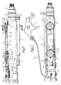
- FIG. 1 and 2 show a section of an axially adjustable steering column 1 which has an axially adjustable steering shaft 2 which is surrounded by two tubular casing parts 3 and 4 which are telescopically pulled together or apart during the axial displacement of the steering shaft 2 can.
- a locking device 5 is provided, which is formed here by a hydraulic piston-cylinder unit aligned parallel to the tubular casing parts 3, 4, each with one end is fixed to a tubular casing part 3 or 4, and on which an actuating part 6 attacks, by the action of the piston rod 7 is retractable or extendable.
- the inner jacket pipe part 3 is displaceable in guides 8 of the outer jacket pipe part 4, which must have a small gap to the inner jacket pipe part 3. Since this means that the inner jacket pipe part 3 is not completely immovable in the outer jacket pipe part 4 even after it has been locked, the jacket pipe parts 3, 4 can be fixed to one another by a clamp connection 9, which serves to clear the play of the two jacket pipe parts 3, 4.
- the clamping connection 9 comprises two threaded pins 10, 11, which are mounted so as to be movable radially to the longitudinal axis of the tubular casing parts 3, 4 in a threaded section 12 which is fixed on the outer tubular casing part 4 and extends through this.
- a cable pull 13 acts on the threaded pins 10, 11 and rotates them about their longitudinal axis, by being connected to each of them via a pin connection part 14 or 15, which is fixed to the threaded pin 10, 11 and at least partially wraps around the cable 13.
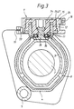
- the pin connecting parts 14, 15 have two circular circumferential grooves 16, 17 and 18, 19 lying axially one above the other. In the circumferential grooves 16 and 18 lying further away from the outer casing tube 4, the cable 13 is guided. The circular contact surface in the circumferential grooves 16, 17, 18, 19 leads to a uniform movement of the cable 13. The diameter of the circumferential grooves 16, 17 and 18, 19, as a lever arm, influences the moment required for the rotation of the threaded pins 10, 11.
- the cable 13 is formed at one end as a Bowden cable 20, the casing of which is supported on a system 21 on the outer casing tube 4 and which is connected to a cable actuation 22.
- the pull actuation 22 has an actuation switch 23 which assumes two fixed positions and pulls the cable 13 with it during this movement. As a result, the cable 13 also takes two positions relative to the threaded pin 10, 11. The cable 13 is first guided around the distant pin connection part 15 of the threaded pin 11 in the circumferential groove 18, where it is hooked on via a connecting bolt 24, and is then directed back to the other pin connection part 14, where its end, after a quarter circle -Wrapping the upper circumferential groove 16 is also hooked with a connecting pin 25.
- the actuation switch 23 is actuated (pivoting downward in FIG.
- the cable pull 13 is pulled, and in the process rotates the threaded pins 11 and 10 through the connecting bolts 24 and 25 from the locking position shown into a release position rotated back approximately 45 degrees, in which the threaded pins 10, 11 no longer sit on the inner tubular casing part 3.
- the pin connecting parts 14, 15 are designed as a cap, which can be placed on an external toothing 27 of the threaded pin 10, 11 in various rotational positions via a toothing 26 visible in FIG. 3.
- the cable 13 is also used to actuate the locking device 5, the actuating part 6 is attached to the cable 13, whereby the locking and clearance of the tubular casing parts 3, 4, and the associated reversing movement is carried out synchronously.
- a threaded pin acts in its locking position with a relatively high force on the inner casing tube part. That is why when it starts to turn it is also necessary High torque, which is why high actuation forces would be necessary if the cable was operated mechanically.
- the threaded pin 11, as shown in Fig. 3 can be divided radially into two sections 34, 35, between which there is a roller bearing 36 in the axial direction, which allows rotation of the sections 34, 35 relative to each other.
Landscapes
- Engineering & Computer Science (AREA)
- Chemical & Material Sciences (AREA)
- Combustion & Propulsion (AREA)
- Transportation (AREA)
- Mechanical Engineering (AREA)
- Steering Controls (AREA)
- Flexible Shafts (AREA)
Applications Claiming Priority (2)
| Application Number | Priority Date | Filing Date | Title |
|---|---|---|---|
| DE4103548 | 1991-02-06 | ||
| DE4103548A DE4103548C1 (enExample) | 1991-02-06 | 1991-02-06 |
Publications (2)
| Publication Number | Publication Date |
|---|---|
| EP0499036A1 EP0499036A1 (de) | 1992-08-19 |
| EP0499036B1 true EP0499036B1 (de) | 1994-03-02 |
Family
ID=6424477
Family Applications (1)
| Application Number | Title | Priority Date | Filing Date |
|---|---|---|---|
| EP92100565A Expired - Lifetime EP0499036B1 (de) | 1991-02-06 | 1992-01-15 | Axial verstellbare Lenksäule für Fahrzeuge |
Country Status (4)
| Country | Link |
|---|---|
| US (1) | US5269562A (enExample) |
| EP (1) | EP0499036B1 (enExample) |
| JP (1) | JP2528414B2 (enExample) |
| DE (1) | DE4103548C1 (enExample) |
Families Citing this family (15)
| Publication number | Priority date | Publication date | Assignee | Title |
|---|---|---|---|---|
| US5744769A (en) | 1993-09-13 | 1998-04-28 | United Technologies Automotive, Inc. | Electrical switch for use in an automotive vehicle |
| US5820163A (en) * | 1996-07-08 | 1998-10-13 | Ford Global Technologies, Inc. | Tilting, telescoping and energy absorbing steering column |
| DE19901300C1 (de) | 1999-01-15 | 2000-07-06 | Daimler Chrysler Ag | Lenksystem |
| US6349611B1 (en) | 2000-03-20 | 2002-02-26 | L & P Property Management Company | Cable operated actuator assembly |
| US6364357B1 (en) | 2000-09-20 | 2002-04-02 | Daimlerchyrsler Corporation | Telescoping steering column and bracket |
| US7021660B2 (en) * | 2002-09-30 | 2006-04-04 | Nsk Steering Systems America, Inc. | Adjustable steering column for motor vehicles |
| US7174804B2 (en) * | 2002-12-03 | 2007-02-13 | Associated Spring Raymond | Positioning mechanism for tilt steering |
| JP2004262433A (ja) * | 2003-02-14 | 2004-09-24 | Nsk Ltd | ステアリングコラム装置 |
| US7066455B2 (en) * | 2003-08-08 | 2006-06-27 | Barnes Group Inc. | Self-centering mechanical strut |
| US20060243089A1 (en) * | 2005-04-28 | 2006-11-02 | Cymbal William D | Telescoping steering shaft |
| DE102005034952B3 (de) | 2005-07-22 | 2007-02-22 | Thyssenkrupp Automotive Ag | Verstellbare Lenksäule für ein Kraftfahrzeug |
| US7770487B2 (en) * | 2007-03-30 | 2010-08-10 | Nissan Technical Center North America, Inc. | Vehicle steering column structure |
| KR101143683B1 (ko) | 2008-03-18 | 2012-05-09 | 주식회사 만도 | 자동차의 버튼식 조향장치 |
| WO2018230587A1 (ja) * | 2017-06-14 | 2018-12-20 | 株式会社山田製作所 | ステアリング装置 |
| DE102017007960A1 (de) | 2017-08-23 | 2018-02-22 | Daimler Ag | Feststellvorrichtung für eine verstellbare Lenksäule eines Fahrzeugs |
Family Cites Families (6)
| Publication number | Priority date | Publication date | Assignee | Title |
|---|---|---|---|---|
| US3245282A (en) * | 1964-04-13 | 1966-04-12 | Gen Motors Corp | Progressively adjustable steering assembly |
| DE2610139C3 (de) * | 1976-03-11 | 1978-10-12 | Maschinenfabrik Augsburg-Nuernberg Ag, 8000 Muenchen | Axialverstellbare Unksäule für Fahrzeuge |
| DE3409988A1 (de) * | 1984-03-19 | 1985-09-26 | Lemförder Metallwaren AG, 2844 Lemförde | Laengenverstellbare lenksaeule |
| DE3638163C1 (de) * | 1986-11-08 | 1988-03-17 | Lemfoerder Metallwaren Ag | Hoehenverstellbare Lenksaeule fuer Kraftfahrzeuge |
| DE3808271C1 (en) * | 1988-03-12 | 1989-10-19 | Lemfoerder Metallwaren Ag, 2844 Lemfoerde, De | Height-adjustable steering column with manual operation |
| US5009120A (en) * | 1990-02-23 | 1991-04-23 | General Motors Corporation | Manual control for adjustable steering column |
-
1991
- 1991-02-06 DE DE4103548A patent/DE4103548C1/de not_active Expired - Lifetime
-
1992
- 1992-01-15 EP EP92100565A patent/EP0499036B1/de not_active Expired - Lifetime
- 1992-01-30 JP JP4054465A patent/JP2528414B2/ja not_active Expired - Lifetime
- 1992-02-03 US US07/829,498 patent/US5269562A/en not_active Expired - Fee Related
Also Published As
| Publication number | Publication date |
|---|---|
| JPH0577736A (ja) | 1993-03-30 |
| DE4103548C1 (enExample) | 1992-04-23 |
| US5269562A (en) | 1993-12-14 |
| JP2528414B2 (ja) | 1996-08-28 |
| EP0499036A1 (de) | 1992-08-19 |
Similar Documents
| Publication | Publication Date | Title |
|---|---|---|
| EP0499036B1 (de) | Axial verstellbare Lenksäule für Fahrzeuge | |
| DE3318935C1 (de) | Verstellbare Lenkeinrichtung fuer Kraftfahrzeuge | |
| DE3785533T2 (de) | Vorrichtung zum ausrichten von rohren. | |
| DE102010013522B4 (de) | Verstellbare Lenkvorrichtung mit mechanischer Speicherung | |
| EP0432420A2 (de) | Gelenkbeschlag fÀ¼r Sitze mit verstellbarer Rückenlehne, insbesondere Kraftfahrzeugsitze | |
| DE3000926C2 (de) | Stativarm für Meßgeräte, insbesondere optische Geräte, wie Kameras oder dergleichen | |
| DE1555465B1 (de) | Einstellbare Lenksaeule fuer Kraftfahrzeuge | |
| EP0377860B1 (de) | Bogenführungstrommel für Druckmaschinen zum Schön- bzw. Schön- und Widerdruck | |
| EP1413821A1 (de) | Stativ | |
| DE2841786C2 (enExample) | ||
| EP0599073A1 (de) | Verstellbare Lenksäule für Kraftfahrzeuge | |
| EP0159649B1 (de) | Schweisszange zum Verbinden von zwei aneinanderstossenden Rohrenden durch Lichtbogenschweissung | |
| EP0442265B1 (de) | Klemmvorrichtung für ein axial verschiebbares Stellglied zur Greiferumsteuerung an einem Greiferzylinder einer Bogenrotationsdruckmaschine | |
| DE69107829T2 (de) | Lenkverriegelungseinrichtung für eine teleskopartige Lenkvorrichtung. | |
| DE10053753C1 (de) | Vorrichtung zum Sperren der Lenkspindel eines Kraftfahrzeugs | |
| EP0858890B1 (de) | Plattenzylinder mit einfügbarem Klemmmechanismus sowie Verfahren für dessen Gebrauch | |
| DE9317971U1 (de) | Spurstangenkopf-Auspreßvorrichtung | |
| DE4446692C2 (de) | Formschließeinrichtung für eine Kunststoffspritzgießmaschine | |
| EP0443456A1 (de) | Stütze | |
| EP0035164B1 (de) | Kraftschrauber | |
| EP0463132A1 (de) | Biegemaschine zum biegen von stabförmigem material. | |
| EP0022121A1 (de) | Stütz- und Führungsgerüst für Stranggiessanlagen | |
| DE2304864A1 (de) | Gleitformeinrichtung bzw. gleitschalung zum giessen eines betonkoerpers | |
| DE19840328C1 (de) | Prüferstange | |
| DE3801630C2 (enExample) |
Legal Events
| Date | Code | Title | Description |
|---|---|---|---|
| PUAI | Public reference made under article 153(3) epc to a published international application that has entered the european phase |
Free format text: ORIGINAL CODE: 0009012 |
|
| 17P | Request for examination filed |
Effective date: 19920612 |
|
| AK | Designated contracting states |
Kind code of ref document: A1 Designated state(s): FR GB IT SE |
|
| 17Q | First examination report despatched |
Effective date: 19930817 |
|
| ITF | It: translation for a ep patent filed | ||
| GRAA | (expected) grant |
Free format text: ORIGINAL CODE: 0009210 |
|
| AK | Designated contracting states |
Kind code of ref document: B1 Designated state(s): FR GB IT SE |
|
| GBT | Gb: translation of ep patent filed (gb section 77(6)(a)/1977) |
Effective date: 19940328 |
|
| ET | Fr: translation filed | ||
| PLBE | No opposition filed within time limit |
Free format text: ORIGINAL CODE: 0009261 |
|
| STAA | Information on the status of an ep patent application or granted ep patent |
Free format text: STATUS: NO OPPOSITION FILED WITHIN TIME LIMIT |
|
| EAL | Se: european patent in force in sweden |
Ref document number: 92100565.8 |
|
| 26N | No opposition filed | ||
| REG | Reference to a national code |
Ref country code: FR Ref legal event code: TP |
|
| REG | Reference to a national code |
Ref country code: GB Ref legal event code: 732E |
|
| REG | Reference to a national code |
Ref country code: GB Ref legal event code: 732E |
|
| PGFP | Annual fee paid to national office [announced via postgrant information from national office to epo] |
Ref country code: GB Payment date: 19991222 Year of fee payment: 9 |
|
| PGFP | Annual fee paid to national office [announced via postgrant information from national office to epo] |
Ref country code: FR Payment date: 20000125 Year of fee payment: 9 |
|
| PGFP | Annual fee paid to national office [announced via postgrant information from national office to epo] |
Ref country code: SE Payment date: 20000126 Year of fee payment: 9 |
|
| PG25 | Lapsed in a contracting state [announced via postgrant information from national office to epo] |
Ref country code: GB Free format text: LAPSE BECAUSE OF NON-PAYMENT OF DUE FEES Effective date: 20010115 |
|
| PG25 | Lapsed in a contracting state [announced via postgrant information from national office to epo] |
Ref country code: SE Free format text: LAPSE BECAUSE OF NON-PAYMENT OF DUE FEES Effective date: 20010116 |
|
| GBPC | Gb: european patent ceased through non-payment of renewal fee |
Effective date: 20010115 |
|
| EUG | Se: european patent has lapsed |
Ref document number: 92100565.8 |
|
| PG25 | Lapsed in a contracting state [announced via postgrant information from national office to epo] |
Ref country code: FR Free format text: LAPSE BECAUSE OF NON-PAYMENT OF DUE FEES Effective date: 20010928 |
|
| REG | Reference to a national code |
Ref country code: FR Ref legal event code: ST |
|
| PG25 | Lapsed in a contracting state [announced via postgrant information from national office to epo] |
Ref country code: IT Free format text: LAPSE BECAUSE OF NON-PAYMENT OF DUE FEES Effective date: 20050115 |