EP0498181A1 - Dispositif pour ajuster le volume récepteur d'un moyen de support d'un objet - Google Patents
Dispositif pour ajuster le volume récepteur d'un moyen de support d'un objet Download PDFInfo
- Publication number
- EP0498181A1 EP0498181A1 EP92100643A EP92100643A EP0498181A1 EP 0498181 A1 EP0498181 A1 EP 0498181A1 EP 92100643 A EP92100643 A EP 92100643A EP 92100643 A EP92100643 A EP 92100643A EP 0498181 A1 EP0498181 A1 EP 0498181A1
- Authority
- EP
- European Patent Office
- Prior art keywords
- workpiece carrier
- side walls
- base plate
- strand
- workpiece
- Prior art date
- Legal status (The legal status is an assumption and is not a legal conclusion. Google has not performed a legal analysis and makes no representation as to the accuracy of the status listed.)
- Granted
Links
Images


Classifications
-
- B—PERFORMING OPERATIONS; TRANSPORTING
- B65—CONVEYING; PACKING; STORING; HANDLING THIN OR FILAMENTARY MATERIAL
- B65B—MACHINES, APPARATUS OR DEVICES FOR, OR METHODS OF, PACKAGING ARTICLES OR MATERIALS; UNPACKING
- B65B59/00—Arrangements to enable machines to handle articles of different sizes, to produce packages of different sizes, to vary the contents of packages, to handle different types of packaging material, or to give access for cleaning or maintenance purposes
- B65B59/001—Arrangements to enable adjustments related to the product to be packaged
-
- B—PERFORMING OPERATIONS; TRANSPORTING
- B65—CONVEYING; PACKING; STORING; HANDLING THIN OR FILAMENTARY MATERIAL
- B65B—MACHINES, APPARATUS OR DEVICES FOR, OR METHODS OF, PACKAGING ARTICLES OR MATERIALS; UNPACKING
- B65B59/00—Arrangements to enable machines to handle articles of different sizes, to produce packages of different sizes, to vary the contents of packages, to handle different types of packaging material, or to give access for cleaning or maintenance purposes
- B65B59/003—Arrangements to enable adjustments related to the packaging material
-
- B—PERFORMING OPERATIONS; TRANSPORTING
- B65—CONVEYING; PACKING; STORING; HANDLING THIN OR FILAMENTARY MATERIAL
- B65B—MACHINES, APPARATUS OR DEVICES FOR, OR METHODS OF, PACKAGING ARTICLES OR MATERIALS; UNPACKING
- B65B59/00—Arrangements to enable machines to handle articles of different sizes, to produce packages of different sizes, to vary the contents of packages, to handle different types of packaging material, or to give access for cleaning or maintenance purposes
- B65B59/005—Adjustable conveying means
Definitions
- the invention relates to a device for adjusting the receiving volume of a workpiece holder which is held in a strand and has approximately tubular side walls.
- a wide variety of conveying devices are known for the transport of workpieces, with the focus here being on conveyors in which the workpiece is received and conveyed in a carrier held on the conveying strand.
- conveying devices preference is given to liquid packs, which are transported directly on conveyor belts even without a carrier, and whose processing, in particular filling and closing, is preferably arranged in a workpiece carrier; for positioning purposes alone.
- a base plate is loosely displaceably arranged in positioning means in the side walls of the workpiece carrier, the Positioning means extend transversely to the conveying direction of the strand, and that a device for receiving and displacing the base plate is attached to at least one positioner which is translationally movable perpendicular to the conveying direction of the strand, guide means of the receiving device being adjustable relative to the positioning means in the side walls of the workpiece carrier.
- the special feature of the new invention is the adjustment of the receiving volume of the workpiece carrier in that the height of the workpiece carrier available for the workpiece is changed. This change is made by inserting the base plate, which is loosely displaceable in the positioning means. If this base plate is attached to the bottom of the workpiece carrier, the largest holding volume is available for the workpieces. With the receiving and displacing devices of the base plate, it is possible to pull the base plate out of its respective position in the workpiece holder, to move it to another location by translatory movement of the holder and to push it back into the workpiece holder. This very simple change in volume can be carried out immediately at any point in the line without loss of capacity of the entire conveyor system.
- the device for receiving and moving the base plate is a simple means and can be designed in various ways.
- the workpiece carrier has the shape of a substantially flat side walls, the box, that at least at least one extending transversely to the conveying direction and overlapping the strand in the direction of extension rectilinearly reciprocable and / or rotatable push rod, two guide plates are fastened parallel to one another and at a distance from one another which is greater than the width of the side walls of the workpiece carrier holding the base plate, that the device for receiving and displacing the base plate as a holding fork is configured, which is fastened to the positioner designed as a positioning rod, the positioning rod extending perpendicular to the push rod, and that the guide plates in and out of the area of the U-shaped holding fork in plan view are movable.
- the invention is based on a box-shaped workpiece carrier which has at least two essentially flat side walls.
- the workpiece to be conveyed for example an empty or filled liquid pack of paper, lies between the two side walls and is precisely positioned and moved with the movement of the workpiece carrier.
- the workpiece for example the liquid pack, is usually inserted into the Carrier inserted that the upper edge of both the carrier and the workpiece are at the same height.
- the base plate supporting the workpiece from below is in a lower position.
- the invention is based on changing the receiving volume of the workpiece carrier or its depth in the longitudinal direction of the side walls, which is to be considered vertically in the preferred application, by setting a base plate to different levels in each individual workpiece carrier . It is understandable that the holding volume of the workpiece carrier is smaller if the base plate is set at a higher level, i.e. closer to the upper edge of the workpiece holder, than if the base plate is in the lowest possible lower position (maximum holding volume).
- the teaching of the invention does not consist solely of the idea of changing the receiving volume of the workpiece carrier by moving the base plate, but is primarily concerned with the means of how this base plate can be moved mechanically and, if possible, automatically or in a controlled manner from one position to another .
- the solution is proposed to move the base plate by means of two guide plates which are attached to movable push rods. If, in a preferred embodiment, the position of the base plate is assumed to be horizontal, then the respective guide plate is to be considered perpendicular to it, the plane of each guide plate extending parallel to the conveying direction.
- the predetermined distance between the two guide plates makes it possible to operate the conveyor independently of the adjustment device.
- the workpiece carriers with the strand are moved through the adjusting device, in particular one workpiece carrier being moved through a pair of guide plates. This can be seen as the zero position of the guide plates.
- the adjusting device can be switched on without any time delay when the intermittently moving conveyor is at a standstill. Switching on causes the push rod to be moved in such a way that the base plate which is loosely held by the side walls is pushed out laterally, ie transversely to the conveying direction, by the guide plate arranged in the pushing direction at the rear.
- a holding fork is arranged laterally next to the push rod on a positioning rod and provided with guide means on the inside in such a way that the base plate inserted into the holding fork from the rear guide plate comes to lie exactly in the guide means.
- the push rod and thus the two guide plates are displaced into the area of the holding fork to such an extent that the base plate finally lies completely in the holding fork and has become free of the workpiece carrier.
- the base plate can now be raised or lowered to another level of the box-shaped workpiece carrier.
- the push rod then moves the base plate in the opposite direction out of the holding fork into the positioning means of the side walls of the workpiece carrier, and the receiving volume of the workpiece carrier is thus adjusted in the desired manner.
- the measures according to the invention allow the base plate to be removed from the workpiece carrier at any point on a conveyor by means of corresponding guide plate pairs and to be pushed back in at another point, so that the adjustment of the receiving volume at almost any point of a conveyor can be ensured with simple means .
- the volume adjustment according to the invention can be started and closed again at any time during the conveying without loss of capacity. It is therefore not necessary to empty a conveyor section - as in known devices - of workpieces in order to then mount lifting rails or the like, but rather to start changing the volume at any desired point in the line and at any time. Without adjustment, the strand with the workpiece carriers runs through the adjustment device without touching or influencing it.
- the plane of the side walls with the positioning means is preferably vertical and transverse to the conveying direction of the strand. Then the base plate can be easily pushed out of the push rod arranged in the manner described, adjusted in height and pushed back into the workpiece carrier.
- the positioning means can be formed by the projections, projections, buttons, strips, rails or the like protruding from the opposing surfaces of the side walls.
- pairs of opposing, parallel, straight grooves are provided at a distance above one another as positioning means and that the guide means of the U-shaped holding fork are also grooves whose open sides are opposite one another.
- Such a U-shaped holding fork can be constructed particularly firmly if the mentioned positioning rod for the holding fork is attached to the web connecting its free legs of the U.
- the plane spanned by the U of the holding fork is then perpendicular to the positioning rod, which in a preferred embodiment runs vertically.
- the main plane of the holding fork is then horizontal, as is the base plate in the workpiece carrier.
- the side wall of the workpiece carrier is made of a solid material, preferably stainless steel, then it can easily be introduced as a positioning means when producing a groove.
- a position groove also stiffens the side wall like a bead.
- the cross section of the groove preferably has a V shape with the tip of the V pointing outwards.
- the respective base plate can then be inserted into the grooves in the opposite side walls of the workpiece carrier as in rails. Even heavy workpieces are guided correctly and precisely from such a base plate in a workpiece carrier designed in this way.
- the workpiece carrier consists of four substantially flat side walls which are connected to one another along the four edges of the tube formed thereby and a fixed base which is arranged transversely thereto, two of the four side walls which have no positioning means being left at a distance from The floor is shortened.
- the shortened shape of two opposite side walls not only saves material and reduces the weight of the workpiece carrier, it also results in better movement options for pushing out and pushing in the respective base plate.
- the positioning grooves should namely be arranged at such a height in the two large side walls that there is no interference or blocking by the two side walls arranged transversely thereto, i.e. thus outside the area of the shortened side walls.
- a window is formed which extends through the entire workpiece carrier and through which the above-mentioned guide plates can be pushed.
- a holding plate is provided for fastening and holding the workpiece carrier on the strand.
- the side wall should preferably be a cuboid-shaped space, that is, a space in the form of a very flat cuboid, because in this space in the zero position the guide plates are arranged without engagement with the workpiece carriers, or, when the conveyor is running, they run past the workpiece carriers.
- This free space results from the fact that the holding plate is pulled down parallel to the workpiece carrier down to its longitudinal center position. This allows the workpiece carrier to be attached to the strand in the region of its center of gravity, so that the workpiece carrier is held on the strand much more strongly.
- the intended design of the workpiece carrier is not only inherently torsion-resistant but is also firmly held and nevertheless it is possible to run past the guide plates when the adjusting device is switched off.
- the bottom plate loosely held in the workpiece carrier is square in plan view and has at least one recess extending from at least one edge towards the center and if the edge preferably projects outwards, particularly preferably in cross section V-shaped with an outwardly pointing tip.
- the base plate can be made of any hard material, preferably a hard plastic, because its production and friction properties with the position grooves in the side walls of the workpiece carrier are very favorable.
- the base plate should be formed in a top view, i.e. also e.g. square.
- the insertion of the base plate into the position grooves of the workpiece carrier is further facilitated in that the four corners of the base plate are cut off, as seen in plan view, so that small triangles are omitted at the corners.
- the base plate has three elongated recesses next to one another and lying parallel to one another and extending beyond the center.
- the recess extending from the edge to the central region of the base plate generally serves the spring action, which is why the elongated recesses last described here can also be referred to as spring grooves.
- the pushing out of the workpiece carrier and pushing in after moving in height must function properly without any tilting, blocking or the like.
- the recesses in the base plate compensate for small tolerances, so that pushing in in any case or even guiding the base plate out into the workpiece carrier or out of it easily.
- the strand has a self-contained row of links abutting end faces, in which recesses are provided for engagement with guide rails which support the links in the sections, with at least one workpiece carrier on each link is inextricably attached. It can also be imagined that each link holds a workpiece carrier on its two transverse sides, so that the workpiece carriers are always moved in pairs in the conveying direction.
- the guide plates can be attached in pairs to the movable push rod and lie in the non-operational position next to the conveyor line so that the workpiece carriers pass freely through the adjusting device; on the other hand, with the adjustment device switched on, the guide plates can slide out a base plate on each side and move them back into the respective workpiece carriers after being moved.
- the adjusting device according to the invention can also be used in a conveyor device in which the strand is driven to rotate endlessly around two deflection wheels, so that two straight and two curved sections are formed, the workpiece carriers being supported via the links by means of the guide rails.
- the guide rails support the links in the straight sections from opposite sides and in the curved sections from the outside.
- the adjusting device according to the invention can be used both in the straight and in the curved section of the conveyor.
- the adjustment device according to the invention is particularly suitable for use in the transport or conveyance of tubular plastic flux packs which are open on one side in a machine for producing and / or filling and / or closing such packs.
- tubular plastic flux packs which are open on one side in a machine for producing and / or filling and / or closing such packs.
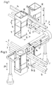
- the links 4 lie against one another via end faces 16 in a manner not shown here and have groove-shaped recesses 10 and 15 for the engagement with the guide rails 1, 1 'in the longitudinal direction or conveying direction 2.
- the flat side walls 22 are by means of the respective holding plate 39 Bores 21, generally designated 5, are attached to the workpiece carriers, which are taken out and shown in perspective in FIGS. 5A and 5B.
- FIG. 1 shows an illustration of the upper straight run of a conveyor and in FIGS. 3 and 4 a part is cut out of the lower straight conveyor section.
- the inner guide rails 1 'arranged parallel to one another are shown in FIG. 1 at the bottom and in FIGS. 3 and 4 at the top in relation to the link 4.
- FIGS. 5A and 5B Workpiece carrier 5 shown explained.
- This consists of four levels and side walls 35, 36, 37, 38 connected to one another along the edges of the tube formed thereby, of which the surface 38 facing the strand 3 is a shortened wall, which even merges into a holding plate 39.
- This holding plate 39 lies at a distance d in the transverse direction (arrow 8) to the conveying direction 2 from the inner edge 6 of the side wall 35 and 37.
- This distance d is necessary for the guide plate 9, 9 'in the rest position of FIG Adjustment device can be moved next to the tool holder 5.
- the box-shaped workpiece carrier 5 is closed by a base 32, which can be seen at the top in the illustration of FIGS.
- the hole shown in the bottom 32 serves on the one hand to save material and weight; however, it also serves to reduce the surface area on which bacteria could form and collect in a milk packaging machine. Through this hole one can spray cleaning agents better or even insert tools which have to carry out work within the workpiece holder 5. With the holes 21 of the holding plate 39, the workpiece carriers 5 are fastened to the respective link 4, that is to say by means of bolts.
- the base plate 14 which is loosely displaceable in the position grooves 13, 13 ', 13' ', is pulled out by hand and pushed back in at another height.
- the purpose of the adjustment device is, however, the automatic displacement and relocation of the base plate 14. This is done with the device which is shown in FIG. 2 alone.
- the left half with the rear push rod 17 is first explained.
- the right half is structured analogously, and the corresponding parts are provided with a subscription verse with the same reference numbers.
- Both push rods 17, 17 ' are parallel to each other.
- a bracket 18 is attached, to which an outer guide plate 11 is attached, to which the inner guide plate 9 is attached in parallel via the bracket 19.
- Both push rods 17, 17 ' can be moved in the direction of the double arrow 8, that is to say transversely to the conveying direction 2, namely the push rod 17 counter to the push rod 17', so that the pair of left guide plates 9, 11 to the left and at the same time the pair of the right Guide plates 9 ', 11' are moved to the right.
- the push rods 17, 17 ' are held and guided in guide sleeves 23 and are driven by a drive device 24.
- the positioning rods 27, 27 ' can be raised or lowered in the vertical direction according to double arrow 29 in order to raise the respective base plate 14 to a different level of position grooves 13 when adjusting the receiving volume, e.g. from 13 to 13 '; from 13 'to 13' '; or the other way around.
- the base plate 14 is shown in a first embodiment in plan view in FIG. 6 and in a second embodiment in plan view in FIG. 7.
- the general shape of the bottom plate 14 in plan view is square with cut corners. 6 and 7, the bottom plate 14 has an upper edge 30 and a lower opposite edge 31, respectively.
- a recess, generally designated 33 extends only from the upper edge 30 to the center of the base plate 14, which initially begins as an elongated recess 33 'and then opens into a circular opening. It goes without saying that the upper edge 30 in the embodiment of the base plate 14 according to FIG. 7 can be shortened or pulled apart by bending.
- an elongated recess 33 ′ extends from the upper edge 30 to approximately the middle.
- they also extend from the opposite one lower edge 31 at a distance next to each other two further parallel elongated recesses 33 "from bottom to top and even beyond the center of the base plate, ie over the line 34 lying horizontally in FIG. 6.
- the side view of the bottom plate 14, e.g. 6 and 7 looking from left to right looks like that shown in FIG. 6A.
- the straight edges are projecting outwards and have a V-shaped cross-section with the tip pointing outwards.
- the guide plates 9, 11 and 9 ', 11' are in the position of FIG. 3, so that the workpiece carriers 5 can be conveyed through the adjustment device in the direction of the arrow 2. It is assumed that the workpiece carriers 5 carry the base plates 14 in the lowest pair of position grooves 13 ′′. Before switching on for moving the base plates 14, the positioning rods 27, 27 'have moved upwards in the direction of the double arrow 29 into the highest position. Here the guide grooves 26 of the holding forks 25, 25 'are now exactly opposite the position groove pair 13 "at the correct height.
- the rear push rod 17 moves to the left and the front push rod 17 'to the right in the transverse direction of the double arrow 8, so that the position in FIG. 4 is reached.
- the pair of guide plates 9, 11 on the left side or 9 ', 11' on the right side has gripped the respective base plate 14 and pushed it out of the positioning grooves 13 '' and into the guide grooves 26 of the holding forks 25, 25 ' .
- the base plates 14 can be moved vertically in the direction of the double arrow 29 downwards and upwards without interference. If the shift from the position of FIG. 4 downwards occurs e.g.
Landscapes
- Mechanical Engineering (AREA)
- Engineering & Computer Science (AREA)
- Special Conveying (AREA)
- Attitude Control For Articles On Conveyors (AREA)
- Specific Conveyance Elements (AREA)
- Framework For Endless Conveyors (AREA)
- Constituent Portions Of Griding Lathes, Driving, Sensing And Control (AREA)
- Grinding Of Cylindrical And Plane Surfaces (AREA)
- Signal Processing Not Specific To The Method Of Recording And Reproducing (AREA)
- Reduction Or Emphasis Of Bandwidth Of Signals (AREA)
- Sampling And Sample Adjustment (AREA)
- Finish Polishing, Edge Sharpening, And Grinding By Specific Grinding Devices (AREA)
- Control Of Amplification And Gain Control (AREA)
- Chain Conveyers (AREA)
- Supplying Of Containers To The Packaging Station (AREA)
Applications Claiming Priority (2)
| Application Number | Priority Date | Filing Date | Title |
|---|---|---|---|
| DE4103479A DE4103479C2 (de) | 1991-02-06 | 1991-02-06 | Vorrichtung zum Verstellen des Aufnahmevolumens eines Gutträgers |
| DE4103479 | 1991-02-06 |
Publications (2)
| Publication Number | Publication Date |
|---|---|
| EP0498181A1 true EP0498181A1 (fr) | 1992-08-12 |
| EP0498181B1 EP0498181B1 (fr) | 1994-06-08 |
Family
ID=6424437
Family Applications (1)
| Application Number | Title | Priority Date | Filing Date |
|---|---|---|---|
| EP92100643A Expired - Lifetime EP0498181B1 (fr) | 1991-02-06 | 1992-01-16 | Dispositif pour ajuster le volume récepteur d'un moyen de support d'un objet |
Country Status (9)
| Country | Link |
|---|---|
| US (1) | US5216955A (fr) |
| EP (1) | EP0498181B1 (fr) |
| JP (1) | JP3222911B2 (fr) |
| AT (1) | ATE106823T1 (fr) |
| AU (1) | AU648139B2 (fr) |
| CA (1) | CA2060774A1 (fr) |
| DE (2) | DE4103479C2 (fr) |
| DK (1) | DK0498181T3 (fr) |
| ES (1) | ES2054511T3 (fr) |
Cited By (4)
| Publication number | Priority date | Publication date | Assignee | Title |
|---|---|---|---|---|
| EP2163498A1 (fr) * | 2008-09-11 | 2010-03-17 | Motor Power Company S.r.l. | Dispositif pour le déplacement et la mise en place de produits et machine équipée dudit dispositif |
| CN107775734A (zh) * | 2016-08-31 | 2018-03-09 | 浙江粤强家具科技有限公司 | 一种切割机及其使用方法 |
| CN107826717A (zh) * | 2017-11-17 | 2018-03-23 | 贵阳普天物流技术有限公司 | 一种烟箱推烟机构 |
| CN111085460A (zh) * | 2019-12-19 | 2020-05-01 | 安徽工程大学 | 一种生产线自动化包装箱分拣装置 |
Families Citing this family (8)
| Publication number | Priority date | Publication date | Assignee | Title |
|---|---|---|---|---|
| DE4137098C2 (de) * | 1991-11-12 | 1996-06-05 | Tetra Pak Gmbh | Vorrichtung zum Verstellen des Aufnahmevolumens eines Gutträgers |
| US7250582B2 (en) | 2002-10-08 | 2007-07-31 | Lockheed Martin Corporation | Method and system for sequentially ordering objects using a single pass delivery point process |
| CN108147112B (zh) * | 2017-12-18 | 2021-01-08 | 广东科达洁能股份有限公司 | 一种双倍速移砖机构 |
| CN112009922A (zh) * | 2019-05-31 | 2020-12-01 | 河南许继仪表有限公司 | 柱状物料提取装置 |
| CN110203685B (zh) * | 2019-06-03 | 2020-10-27 | 浙江镭众科技有限公司 | 一种废纸碎片混合物接料搬运机构 |
| CN111332560B (zh) * | 2020-03-13 | 2022-02-08 | 集美大学 | 一种包装设备的料仓宽调夹紧装置 |
| CN111960322B (zh) * | 2020-08-10 | 2021-09-14 | 嘉兴久珥科技有限公司 | 一种基于机械的手动式支撑抬升推力结构 |
| CN113184929B (zh) * | 2021-04-20 | 2022-09-27 | 江西四季景观建设有限公司 | 一种环保工程废水处理回收利用系统 |
Citations (3)
| Publication number | Priority date | Publication date | Assignee | Title |
|---|---|---|---|---|
| CH410757A (de) * | 1962-06-08 | 1966-03-31 | Hesser Ag Maschf | Maschine zum Herstellen von Packungen |
| US3608701A (en) * | 1969-06-03 | 1971-09-28 | Jones & Co Inc R A | Product bucket for cartoning machine |
| DE2658014A1 (de) * | 1976-12-17 | 1978-06-29 | Roy H Straub | Vorrichtung und verfahren zum fuellen von kunststofflaschen mit flexiblen waenden |
Family Cites Families (12)
| Publication number | Priority date | Publication date | Assignee | Title |
|---|---|---|---|---|
| US4203696A (en) * | 1975-08-18 | 1980-05-20 | Lindberg Gunnar Vilhelm | Tray unloading device |
| US4636137A (en) * | 1980-10-24 | 1987-01-13 | Lemelson Jerome H | Tool and material manipulation apparatus and method |
| DE3412575A1 (de) * | 1984-04-04 | 1985-10-17 | Rudolf Geiger Maschinenbau, 8553 Ebermannstadt | Foerdervorrichtung |
| US4634333A (en) * | 1984-10-19 | 1987-01-06 | Doran Brothers Inc. | Conveyor line loader for multi-tiered rolling carts |
| US4807421A (en) * | 1985-07-19 | 1989-02-28 | Mitsubishi Jukogyo Kabushiki Kaisha | Equipment for handling various containers |
| DE3538993C1 (en) * | 1985-11-02 | 1987-04-02 | Benz & Hilgers Gmbh | Apparatus for automatically exchanging cellular sheets in container-filling machines |
| DE3632691A1 (de) * | 1985-11-02 | 1988-04-07 | Benz & Hilgers Gmbh | Verfahren und vorrichtung zum wechseln von behaelteraufnahmen aufweisenden zellenblechen einer fuellmaschine, insbesondere fuer nahrungs- und genussmittel |
| DE3618971C1 (en) * | 1986-06-05 | 1987-04-09 | Benz & Hilgers Gmbh | Apparatus for changing elongate container cells in a container-filling machine for foodstuffs and semi-luxuries |
| FR2607479B1 (fr) * | 1986-12-01 | 1991-02-15 | Remy & Cie E P | Dispositif de prehension et de retenue d'objets, tels que par exemple des recipients, sur un convoyeur, et convoyeur equipe de ce dispositif |
| EP0302542B1 (fr) * | 1987-07-14 | 1994-01-26 | Koninklijke Philips Electronics N.V. | Dispositif pour transporter des supports à partir et en direction d'un dispositif de positionnement et dispositif sélecteur destiné à un dispositif |
| JPH0617295Y2 (ja) * | 1987-11-27 | 1994-05-02 | 大日本スクリーン製造株式会社 | 基板受け渡し装置 |
| US5104277A (en) * | 1989-04-06 | 1992-04-14 | Hewlett-Packard Company | Method and apparatus for automatically changing printed circuit board test fixtures |
-
1991
- 1991-02-06 DE DE4103479A patent/DE4103479C2/de not_active Expired - Fee Related
-
1992
- 1992-01-16 DK DK92100643.3T patent/DK0498181T3/da active
- 1992-01-16 DE DE59200210T patent/DE59200210D1/de not_active Expired - Fee Related
- 1992-01-16 ES ES92100643T patent/ES2054511T3/es not_active Expired - Lifetime
- 1992-01-16 EP EP92100643A patent/EP0498181B1/fr not_active Expired - Lifetime
- 1992-01-16 AT AT92100643T patent/ATE106823T1/de not_active IP Right Cessation
- 1992-01-27 US US07/825,933 patent/US5216955A/en not_active Expired - Fee Related
- 1992-01-28 AU AU10509/92A patent/AU648139B2/en not_active Ceased
- 1992-02-05 JP JP02010892A patent/JP3222911B2/ja not_active Expired - Fee Related
- 1992-02-06 CA CA002060774A patent/CA2060774A1/fr not_active Abandoned
Patent Citations (3)
| Publication number | Priority date | Publication date | Assignee | Title |
|---|---|---|---|---|
| CH410757A (de) * | 1962-06-08 | 1966-03-31 | Hesser Ag Maschf | Maschine zum Herstellen von Packungen |
| US3608701A (en) * | 1969-06-03 | 1971-09-28 | Jones & Co Inc R A | Product bucket for cartoning machine |
| DE2658014A1 (de) * | 1976-12-17 | 1978-06-29 | Roy H Straub | Vorrichtung und verfahren zum fuellen von kunststofflaschen mit flexiblen waenden |
Cited By (5)
| Publication number | Priority date | Publication date | Assignee | Title |
|---|---|---|---|---|
| EP2163498A1 (fr) * | 2008-09-11 | 2010-03-17 | Motor Power Company S.r.l. | Dispositif pour le déplacement et la mise en place de produits et machine équipée dudit dispositif |
| CN107775734A (zh) * | 2016-08-31 | 2018-03-09 | 浙江粤强家具科技有限公司 | 一种切割机及其使用方法 |
| CN107826717A (zh) * | 2017-11-17 | 2018-03-23 | 贵阳普天物流技术有限公司 | 一种烟箱推烟机构 |
| CN107826717B (zh) * | 2017-11-17 | 2023-11-07 | 贵阳普天物流技术有限公司 | 一种烟箱推烟机构 |
| CN111085460A (zh) * | 2019-12-19 | 2020-05-01 | 安徽工程大学 | 一种生产线自动化包装箱分拣装置 |
Also Published As
| Publication number | Publication date |
|---|---|
| AU1050992A (en) | 1992-09-10 |
| JP3222911B2 (ja) | 2001-10-29 |
| ES2054511T3 (es) | 1994-08-01 |
| DE4103479C2 (de) | 1995-04-20 |
| AU648139B2 (en) | 1994-04-14 |
| US5216955A (en) | 1993-06-08 |
| JPH0656127A (ja) | 1994-03-01 |
| EP0498181B1 (fr) | 1994-06-08 |
| DE4103479A1 (de) | 1992-08-13 |
| DK0498181T3 (da) | 1994-08-15 |
| CA2060774A1 (fr) | 1992-08-07 |
| ATE106823T1 (de) | 1994-06-15 |
| DE59200210D1 (de) | 1994-07-14 |
Similar Documents
| Publication | Publication Date | Title |
|---|---|---|
| EP1268319B1 (fr) | Dispositif convoyeur equipe de supports de packs | |
| EP0498181B1 (fr) | Dispositif pour ajuster le volume récepteur d'un moyen de support d'un objet | |
| DE2930150C2 (de) | Transportvorrichtung an einer Verpackungsmaschine mit mehreren, in einem Maschinengestell nebeneinander angeordneten Endlosförderern | |
| EP0477468B1 (fr) | Dispositif de transport pour supports de pièces | |
| EP0093409B1 (fr) | Dispositif pour le transport stabile et synchrone d'emballages pour produits fluides dans des postes de traitement | |
| EP3235389B1 (fr) | Récipient destiné à recevoir ou à délivrer des portions d'un article en forme de tige provenant d'un débit massique de produit formé par l'industrie du tabac et système de discrétisation ou de formation d'un débit massique de produit comprenant de tels récipients | |
| DE4329179A1 (de) | Maschine zum Umsetzen von Artikeln in eine Verpackungseinheit | |
| EP0541985B1 (fr) | Appareil pour modifier le volume de réception d'un porte-pièce | |
| EP0476301A1 (fr) | Dispositif pour déposer des marchandises empilables, comme par exemple des tranches de fromage, ou de saucisson, des biscuits et produits similaires | |
| EP1302419B1 (fr) | Procédé et dispositif d' application définie de produits sur une chaîne transporteuse en forme d' éventail | |
| DE102004050197A1 (de) | Einschubeinheit zum Einschieben eines Produktes in ein Verpackungsbehältnis | |
| EP2944390A2 (fr) | Outil de pliage et unité de changement associée | |
| DE3301013A1 (de) | Sammelpackmaschine | |
| EP1634815A1 (fr) | Conteneur emboitable et empilable | |
| CH620883A5 (en) | Device for stacking drums provided with stacking grooves | |
| DE3815557A1 (de) | Verbundmaschine zum automatischen verpacken von packgut in faltschachteln | |
| DE3002355C2 (de) | Käsepresse | |
| DE1531804A1 (de) | Maschine zum UEberfuehren von Verpackungsgegenstaenden auf Tablette | |
| DE4205197C2 (de) | Vorrichtung zum Einfüllen von Füllgut in eine Hülle, insbesondere einen Briefumschlag | |
| DE19806111B4 (de) | Transport- und Positioniervorrichtung für ein Packungsgebinde | |
| DE4111632C2 (de) | Montagelinie | |
| EP1148014A2 (fr) | Dispositif de formation de piles | |
| DE19525792C2 (de) | Arbeitsplatzsystem | |
| DE2902529C2 (fr) | ||
| CH658235A5 (en) | Apparatus for stacking articles in bar form |
Legal Events
| Date | Code | Title | Description |
|---|---|---|---|
| PUAI | Public reference made under article 153(3) epc to a published international application that has entered the european phase |
Free format text: ORIGINAL CODE: 0009012 |
|
| AK | Designated contracting states |
Kind code of ref document: A1 Designated state(s): AT BE CH DE DK ES FR GB GR IT LI LU MC NL PT SE |
|
| 17P | Request for examination filed |
Effective date: 19920713 |
|
| RAP1 | Party data changed (applicant data changed or rights of an application transferred) |
Owner name: TETRA ALFA HOLDINGS S.A. |
|
| 17Q | First examination report despatched |
Effective date: 19930805 |
|
| RAP1 | Party data changed (applicant data changed or rights of an application transferred) |
Owner name: TETRA LAVAL HOLDINGS & FINANCE S.A. |
|
| GRAA | (expected) grant |
Free format text: ORIGINAL CODE: 0009210 |
|
| ITF | It: translation for a ep patent filed |
Owner name: STUDIO INGG. FISCHETTI & WEBER |
|
| AK | Designated contracting states |
Kind code of ref document: B1 Designated state(s): AT BE CH DE DK ES FR GB GR IT LI LU MC NL PT SE |
|
| REF | Corresponds to: |
Ref document number: 106823 Country of ref document: AT Date of ref document: 19940615 Kind code of ref document: T |
|
| ET | Fr: translation filed | ||
| GBT | Gb: translation of ep patent filed (gb section 77(6)(a)/1977) |
Effective date: 19940607 |
|
| REF | Corresponds to: |
Ref document number: 59200210 Country of ref document: DE Date of ref document: 19940714 |
|
| REG | Reference to a national code |
Ref country code: ES Ref legal event code: FG2A Ref document number: 2054511 Country of ref document: ES Kind code of ref document: T3 |
|
| REG | Reference to a national code |
Ref country code: DK Ref legal event code: T3 |
|
| REG | Reference to a national code |
Ref country code: GR Ref legal event code: FG4A Free format text: 3013159 |
|
| SC4A | Pt: translation is available |
Free format text: 940609 AVAILABILITY OF NATIONAL TRANSLATION |
|
| EAL | Se: european patent in force in sweden |
Ref document number: 92100643.3 |
|
| PLBE | No opposition filed within time limit |
Free format text: ORIGINAL CODE: 0009261 |
|
| STAA | Information on the status of an ep patent application or granted ep patent |
Free format text: STATUS: NO OPPOSITION FILED WITHIN TIME LIMIT |
|
| 26N | No opposition filed | ||
| PGFP | Annual fee paid to national office [announced via postgrant information from national office to epo] |
Ref country code: MC Payment date: 19960102 Year of fee payment: 5 |
|
| PG25 | Lapsed in a contracting state [announced via postgrant information from national office to epo] |
Ref country code: MC Effective date: 19970731 |
|
| PGFP | Annual fee paid to national office [announced via postgrant information from national office to epo] |
Ref country code: FR Payment date: 19991231 Year of fee payment: 9 |
|
| PGFP | Annual fee paid to national office [announced via postgrant information from national office to epo] |
Ref country code: AT Payment date: 20000103 Year of fee payment: 9 Ref country code: SE Payment date: 20000103 Year of fee payment: 9 |
|
| PGFP | Annual fee paid to national office [announced via postgrant information from national office to epo] |
Ref country code: DK Payment date: 20000106 Year of fee payment: 9 |
|
| PGFP | Annual fee paid to national office [announced via postgrant information from national office to epo] |
Ref country code: LU Payment date: 20000113 Year of fee payment: 9 |
|
| PGFP | Annual fee paid to national office [announced via postgrant information from national office to epo] |
Ref country code: PT Payment date: 20000114 Year of fee payment: 9 |
|
| PGFP | Annual fee paid to national office [announced via postgrant information from national office to epo] |
Ref country code: BE Payment date: 20000125 Year of fee payment: 9 |
|
| PG25 | Lapsed in a contracting state [announced via postgrant information from national office to epo] |
Ref country code: AT Free format text: LAPSE BECAUSE OF NON-PAYMENT OF DUE FEES Effective date: 20010116 Ref country code: LU Free format text: LAPSE BECAUSE OF NON-PAYMENT OF DUE FEES Effective date: 20010116 Ref country code: DK Free format text: LAPSE BECAUSE OF NON-PAYMENT OF DUE FEES Effective date: 20010116 |
|
| PG25 | Lapsed in a contracting state [announced via postgrant information from national office to epo] |
Ref country code: SE Free format text: LAPSE BECAUSE OF NON-PAYMENT OF DUE FEES Effective date: 20010117 |
|
| PG25 | Lapsed in a contracting state [announced via postgrant information from national office to epo] |
Ref country code: BE Free format text: LAPSE BECAUSE OF NON-PAYMENT OF DUE FEES Effective date: 20010131 |
|
| BERE | Be: lapsed |
Owner name: S.A. TETRA LAVAL HOLDINGS & FINANCE Effective date: 20010131 |
|
| PG25 | Lapsed in a contracting state [announced via postgrant information from national office to epo] |
Ref country code: PT Free format text: LAPSE BECAUSE OF NON-PAYMENT OF DUE FEES Effective date: 20010731 |
|
| EUG | Se: european patent has lapsed |
Ref document number: 92100643.3 |
|
| REG | Reference to a national code |
Ref country code: DK Ref legal event code: EBP |
|
| PG25 | Lapsed in a contracting state [announced via postgrant information from national office to epo] |
Ref country code: FR Free format text: LAPSE BECAUSE OF NON-PAYMENT OF DUE FEES Effective date: 20010928 |
|
| REG | Reference to a national code |
Ref country code: FR Ref legal event code: ST |
|
| REG | Reference to a national code |
Ref country code: PT Ref legal event code: MM4A Free format text: LAPSE DUE TO NON-PAYMENT OF FEES Effective date: 20010731 |
|
| REG | Reference to a national code |
Ref country code: GB Ref legal event code: IF02 |
|
| PGFP | Annual fee paid to national office [announced via postgrant information from national office to epo] |
Ref country code: NL Payment date: 20020107 Year of fee payment: 11 |
|
| PGFP | Annual fee paid to national office [announced via postgrant information from national office to epo] |
Ref country code: GR Payment date: 20020124 Year of fee payment: 11 |
|
| PG25 | Lapsed in a contracting state [announced via postgrant information from national office to epo] |
Ref country code: NL Free format text: LAPSE BECAUSE OF NON-PAYMENT OF DUE FEES Effective date: 20030801 |
|
| PG25 | Lapsed in a contracting state [announced via postgrant information from national office to epo] |
Ref country code: GR Free format text: LAPSE BECAUSE OF NON-PAYMENT OF DUE FEES Effective date: 20030804 |
|
| NLV4 | Nl: lapsed or anulled due to non-payment of the annual fee |
Effective date: 20030801 |
|
| PGFP | Annual fee paid to national office [announced via postgrant information from national office to epo] |
Ref country code: GB Payment date: 20040107 Year of fee payment: 13 |
|
| PGFP | Annual fee paid to national office [announced via postgrant information from national office to epo] |
Ref country code: CH Payment date: 20040126 Year of fee payment: 13 |
|
| PG25 | Lapsed in a contracting state [announced via postgrant information from national office to epo] |
Ref country code: IT Free format text: LAPSE BECAUSE OF NON-PAYMENT OF DUE FEES;WARNING: LAPSES OF ITALIAN PATENTS WITH EFFECTIVE DATE BEFORE 2007 MAY HAVE OCCURRED AT ANY TIME BEFORE 2007. THE CORRECT EFFECTIVE DATE MAY BE DIFFERENT FROM THE ONE RECORDED. Effective date: 20050116 Ref country code: GB Free format text: LAPSE BECAUSE OF NON-PAYMENT OF DUE FEES Effective date: 20050116 |
|
| PG25 | Lapsed in a contracting state [announced via postgrant information from national office to epo] |
Ref country code: CH Free format text: LAPSE BECAUSE OF NON-PAYMENT OF DUE FEES Effective date: 20050131 Ref country code: LI Free format text: LAPSE BECAUSE OF NON-PAYMENT OF DUE FEES Effective date: 20050131 |
|
| GBPC | Gb: european patent ceased through non-payment of renewal fee |
Effective date: 20050116 |
|
| REG | Reference to a national code |
Ref country code: CH Ref legal event code: PL |
|
| PGFP | Annual fee paid to national office [announced via postgrant information from national office to epo] |
Ref country code: ES Payment date: 20060126 Year of fee payment: 15 |
|
| REG | Reference to a national code |
Ref country code: ES Ref legal event code: FD2A Effective date: 20070117 |
|
| PG25 | Lapsed in a contracting state [announced via postgrant information from national office to epo] |
Ref country code: ES Free format text: LAPSE BECAUSE OF NON-PAYMENT OF DUE FEES Effective date: 20070117 |
|
| PGFP | Annual fee paid to national office [announced via postgrant information from national office to epo] |
Ref country code: DE Payment date: 20080229 Year of fee payment: 17 |
|
| PG25 | Lapsed in a contracting state [announced via postgrant information from national office to epo] |
Ref country code: DE Free format text: LAPSE BECAUSE OF NON-PAYMENT OF DUE FEES Effective date: 20090801 |