EP0498134A1 - Reflecting device for a luminous display on the opaque bottom of a transparent panel - Google Patents
Reflecting device for a luminous display on the opaque bottom of a transparent panel Download PDFInfo
- Publication number
- EP0498134A1 EP0498134A1 EP91480019A EP91480019A EP0498134A1 EP 0498134 A1 EP0498134 A1 EP 0498134A1 EP 91480019 A EP91480019 A EP 91480019A EP 91480019 A EP91480019 A EP 91480019A EP 0498134 A1 EP0498134 A1 EP 0498134A1
- Authority
- EP
- European Patent Office
- Prior art keywords
- inscriptions
- transparent
- reflective
- opaque
- light
- Prior art date
- Legal status (The legal status is an assumption and is not a legal conclusion. Google has not performed a legal analysis and makes no representation as to the accuracy of the status listed.)
- Withdrawn
Links
Images


Classifications
-
- G—PHYSICS
- G02—OPTICS
- G02B—OPTICAL ELEMENTS, SYSTEMS OR APPARATUS
- G02B6/00—Light guides; Structural details of arrangements comprising light guides and other optical elements, e.g. couplings
- G02B6/0001—Light guides; Structural details of arrangements comprising light guides and other optical elements, e.g. couplings specially adapted for lighting devices or systems
- G02B6/0011—Light guides; Structural details of arrangements comprising light guides and other optical elements, e.g. couplings specially adapted for lighting devices or systems the light guides being planar or of plate-like form
- G02B6/0081—Mechanical or electrical aspects of the light guide and light source in the lighting device peculiar to the adaptation to planar light guides, e.g. concerning packaging
- G02B6/0086—Positioning aspects
- G02B6/0091—Positioning aspects of the light source relative to the light guide
-
- G—PHYSICS
- G02—OPTICS
- G02B—OPTICAL ELEMENTS, SYSTEMS OR APPARATUS
- G02B6/00—Light guides; Structural details of arrangements comprising light guides and other optical elements, e.g. couplings
- G02B6/0001—Light guides; Structural details of arrangements comprising light guides and other optical elements, e.g. couplings specially adapted for lighting devices or systems
- G02B6/0011—Light guides; Structural details of arrangements comprising light guides and other optical elements, e.g. couplings specially adapted for lighting devices or systems the light guides being planar or of plate-like form
- G02B6/0066—Light guides; Structural details of arrangements comprising light guides and other optical elements, e.g. couplings specially adapted for lighting devices or systems the light guides being planar or of plate-like form characterised by the light source being coupled to the light guide
- G02B6/007—Incandescent lamp or gas discharge lamp
- G02B6/0071—Incandescent lamp or gas discharge lamp with elongated shape, e.g. tube
Definitions
- the lighting of this type of transparent plate, with or without an opaque background, is traditionally carried out by one of the sides of the plate.
- the opposite and perpendicular sections are either closed by profiles, adhesive strips, or other accessories intended to recover more or less the light, or left free and polished then letting escape a large part of the illumination of the plate, especially when the source bright is away from the edges.
- the best known example relates to road signs, in particular that of streets, or the intaglio engraving by the reverse of the letters constituting the names or names of the streets, seen through the transparent surface of the unpainted face, are brightly lit at the beginning of the text, then more and more dimly as these letters become more and more distant from the light source.
- the invention aims to provide solutions to the specifications thus constituted from the 1st to the 5th point described above.
- the invention therefore relates to a reflector device for light display on the opaque background of a transparent plate, for information, advertising or indicative signage, interior or exterior.
- a transparent plate (1) made of cast polymethyl methacrylate, or of polycarbonate with a shiny or anti-reflective surface, having a refractive index higher than that of glass, which plate is opacified on its rear face (7), by means of an acrylic paint or any other material, machinable after drying, and adhering perfectly to this face.
- a thread (6) is formed at a distance (D) from the 3 lateral edges, constituted by a groove of a few millimeters in cross section (X), and a depth (Y) less than 1 to 2 m / m to the thickness of the plate, this net will be filled with an adherent light opaque shade, thus intended to reflect the light, on the surface thus delimited and reserved for inscriptions (15).
- These inscriptions, signs or graphics (15) will be before or after, printed, glued, engraved or included upside down, through the opacified layer (7) to be seen in relief, or not, by transparency and at the place.
- the 4th lateral edge (2) will be enclosed on 2 cms in a hollow core profile (3), closed at the 2 ends, and will receive above and in the axis of the angle of 105 to 120 ° formed by the edge and the bevelled edge, opposite the opaque face, the light source (8) composed of a linear or fractionated light tube, and its accessories.
- the circular reflective net (6) machined in the same way as in the first characteristic will surround the surface reserved for inscriptions (15).
- a small printed electrical circuit (20) will be slipped in there made up of micro-lamps (18) welded together in parallel, hidden from view, on the transparent side, by a plate (5) added and glued 15 m / m high preferably a homogeneous opaque material, and in the same material as the transparent plate.
- the same lamps (18) will illuminate the plate with an opaque bottom, which must be provided with the reflective mesh always machined in the same manner as according to the 1st characteristic, at a distance (D) from the three other lateral edges.
- the device which is the subject of the invention constituted by the reflective net (6) can be applied to other types of embodiments, on all types of transparent plates with opaque background, in equivalent materials, with the addition of elements which would then be unrelated to any inventive contribution.
- the invention is particularly indicated in the manufacture of street signs, signs of all types, number plates of all vehicles.
Landscapes
- Physics & Mathematics (AREA)
- General Physics & Mathematics (AREA)
- Optics & Photonics (AREA)
- Illuminated Signs And Luminous Advertising (AREA)
Abstract
Description
L'éclairement de ce type de plaque transparente, avec ou sans fond opaque, est traditionnellement effectué par l'un des côtés de la plaque. Les tranches opposées et perpendiculaires sont soit obturées par des profilés, bandes adhésives, ou autres accessoires destinés à récupérer plus ou moins la lumière, soit laissées libres et polies laissant alors échapper une grande partie de l'éclairement de la plaque, surtout lorsque la source lumineuse est éloignée des bords. L'exemple le plus connu se rapporte aux plaques de signalisation, notamment celle des rues, ou la gravure en creux par l'envers des lettres constituant les appellations ou noms des rues, vues à travers la surface transparente de la face non peinte, sont éclairées de manière intense au début du texte, puis de plus en plus faiblement à mesure que ces lettres sont de plus en plus éloignées de la source de lumière.The lighting of this type of transparent plate, with or without an opaque background, is traditionally carried out by one of the sides of the plate. The opposite and perpendicular sections are either closed by profiles, adhesive strips, or other accessories intended to recover more or less the light, or left free and polished then letting escape a large part of the illumination of the plate, especially when the source bright is away from the edges. The best known example relates to road signs, in particular that of streets, or the intaglio engraving by the reverse of the letters constituting the names or names of the streets, seen through the transparent surface of the unpainted face, are brightly lit at the beginning of the text, then more and more dimly as these letters become more and more distant from the light source.
La conception onéreuse et l'absence d'efficacité de ce type de plaques le plus souvent réalisées en polymétacrylate de méthyle coulé de marque "ALTUGLAS"® "PLEXIGLAS"® ou "PERSPEX"® selon qu'il s'agisse de fabricants français, allemand, ou hollandais, en matière de plaques de rues éclairantes, n'intéresse qu'assez peu le marché des collectivités publiques du fait de leur mauvais rendement lumineux et de leur peu d'efficacité par rapport à leur prix, leur préférant les plaques de rues traditionnelles, de 4 à 8 fois moins couteuses. Il convenait donc de régler ces problèmes importants :
- 1) réflectoriser la lumière sur toutes les inscriptions de manière uniforme.
- 2) laisser percevoir le relief par transparence, du ler au dernier signe, dans les 3 dimensions.
- 3) laisser libres les tranches polies en leur gardant un faible éclairement et respecter totalement la structure transparente du matériau.
- 4) supprimer l'adjonction par vissage ou collage de matériaux hétérogènes sur l'ensemble des tranches polies, éliminant ainsi le coût de ces matériaux, de leur mise en oeuvre, de leur entretien et leur pérennité problématique.
- 5) délimiter par un filet esthétique la ou les surfaces éclairées par la ou les sources lumineuses.
- 1) reflect the light on all the inscriptions uniformly.
- 2) let the relief be seen by transparency, from the 1st to the last sign, in the 3 dimensions.
- 3) leave the polished slices free, keeping them in a low light and fully respecting the transparent structure of the material.
- 4) eliminate the addition by screwing or gluing of heterogeneous materials on all of the polished sections, thus eliminating the cost of these materials, their implementation, their maintenance and their problematic durability.
- 5) define by an aesthetic net the surface (s) illuminated by the light source (s).
En dehors des avantages mentionnés ci-dessus, on peut en outre remarquer :
- la diversité des sources lumineuses pouvant être employées avec le dispositif
- leur faible consommation et leur rendement élevé.
- l'économie ainsi réalisée
- la simplicité du dispositif.
- the diversity of light sources that can be used with the device
- their low consumption and their high yield.
- the economy thus achieved
- the simplicity of the device.
L'invention a pour objectifs d'apporter les solutions au cahier des charges ainsi constitué du 1er au 5ème point décrit plus haut.The invention aims to provide solutions to the specifications thus constituted from the 1st to the 5th point described above.
L'invention concerne donc un dispositif réflectorisant pour affichage lumineux sur le fond opaque d'une plaque transparente, pour l'information, la signalisation publicitaire ou indicative, intérieure, ou extérieure.The invention therefore relates to a reflector device for light display on the opaque background of a transparent plate, for information, advertising or indicative signage, interior or exterior.
Elle comporte selon une première caractéristique de l'invention illustrée par la planche 1/3 une plaque transparente (1) en polymétacrylate de méthyle coulé, ou en polycarbonate à surface brillante ou antireflet, possédant un indice de réfraction supérieur à celui du verre, laquelle plaque est opacifiée sur sa face arrière (7), au moyen d'une peinture acrylique ou tout autre matière, usinable après séchage, et adhérant parfaitement à cette face. On usine, à distance (D) des 3 bords latéraux, un filet (6) constitué par une gorge de quelques millimètres de section (X), et d'une profondeur (Y) inférieure de 1 à 2 m/m à l'épaisseur de la plaque, ce filet sera rempli d'une teinte claire opaque adhérente, destinée ainsi à réflectoriser la lumière, sur la surface ainsi délimitée et réservée aux inscriptions (15). Ces inscriptions , signes ou graphismes (15), seront au préalable ou ensuite, imprimées, collées, gravées ou incluses à l'envers, au travers de la couche opacifiée (7) pour être vues en relief, ou non, par transparence et à l'endroit. Le 4 ème bord latéral (2) sera enfermé sur 2 cms dans un profilé à âme creuse (3), fermé aux 2 bouts, et recevra au dessus et dans l'axe de l'angle de 105 à 120° formé par le bord et la tranche biseautée, opposé à la face opaque, la source lumineuse (8) composée d'un tube lumineux linéaire ou fractionné, et de ses accessoires .According to a first characteristic of the invention illustrated by sheet 1/3, it comprises a transparent plate (1) made of cast polymethyl methacrylate, or of polycarbonate with a shiny or anti-reflective surface, having a refractive index higher than that of glass, which plate is opacified on its rear face (7), by means of an acrylic paint or any other material, machinable after drying, and adhering perfectly to this face. A thread (6) is formed at a distance (D) from the 3 lateral edges, constituted by a groove of a few millimeters in cross section (X), and a depth (Y) less than 1 to 2 m / m to the thickness of the plate, this net will be filled with an adherent light opaque shade, thus intended to reflect the light, on the surface thus delimited and reserved for inscriptions (15). These inscriptions, signs or graphics (15), will be before or after, printed, glued, engraved or included upside down, through the opacified layer (7) to be seen in relief, or not, by transparency and at the place. The 4th lateral edge (2) will be enclosed on 2 cms in a hollow core profile (3), closed at the 2 ends, and will receive above and in the axis of the angle of 105 to 120 ° formed by the edge and the bevelled edge, opposite the opaque face, the light source (8) composed of a linear or fractionated light tube, and its accessories.
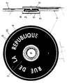
Selon une deuxième caractéristique de l'invention, illustrée par la planche 2/2, l'éclairement issu d'une source lumineuse (2) située au centre de la plaque et constitué ici d'un tube circulaire placé à 4 ou 5 m/m de l'angle de 105 à 120° formé (3) par la tranche de l'évidement circulaire usiné en biseau de 105 à 120°,et la partie externe opposée au fond recouverte par le capot (5), abritant la source lumineuse (2) et ses accessoires de branchement. Le filet réflecteur circulaire (6) usiné de la même manière que dans la première caractéristique cernera la surface réservée aux inscriptions (15).According to a second characteristic of the invention, illustrated by
Selon une troisième caractéristique de l'invention, une gorge (19) de 8 m/m de large et 12 m/m de profondeur, est usinée dans un des 4 bords latéraux. Y sera glissé un petit circuit électrique imprimé (20) constitué de micro lampes (18) soudées entre elles en parallèle, masquées à la vue, du côté transparent, par une plaquette (5) rapportée et collée de 15 m/m de hauteur dans un matériau homogène opaque de préférence, et dans le même matériau que la plaque transparente. Tout au long de cette gorge, les mêmes lampes (18) éclaireront la plaque à fond opaque, qui devra être munie du filet réflecteur toujours usiné de la même manière que selon la 1ère caractéristique, à une distance (D) des trois autres bords latéraux, afin de cerner la surface réservée aux inscriptions (15), pour leur garder le maximum de lumière. Cette solution sera plus particulièrement utilisée dans la fabrication de plaques éclairantes à faible voltage ne nécessitant pas d'accessoires de branchement tel que starter, ou transformateur de tension, avec sortie directe des fils de branchement. Les dessins, les inscriptions ou éléments graphiques (15) disposés du côté du fond opaque (2) de la plaque (1) pour être vus par transparence, seront de préférence gravés (à l'envers et en creux).According to a third characteristic of the invention, a groove (19) 8 m / m wide and 12 m / m deep, is machined in one of the 4 lateral edges. A small printed electrical circuit (20) will be slipped in there made up of micro-lamps (18) welded together in parallel, hidden from view, on the transparent side, by a plate (5) added and glued 15 m / m high preferably a homogeneous opaque material, and in the same material as the transparent plate. Throughout this groove, the same lamps (18) will illuminate the plate with an opaque bottom, which must be provided with the reflective mesh always machined in the same manner as according to the 1st characteristic, at a distance (D) from the three other lateral edges. , in order to identify the area reserved for inscriptions (15), to keep them as much light as possible. This solution will be used more particularly in the manufacture of low-voltage lighting plates that do not require connection accessories such as a choke, or voltage transformer, with direct output from the connection wires. The drawings, inscriptions or graphic elements (15) arranged on the side of the opaque bottom (2) of the plate (1) to be seen by transparency, will preferably be engraved (upside down and recessed).
Comme on pourra l'observer dans les 3 caractéristiques précédentes, le dispositif objet de l'invention constitué par le filet réflecteur (6) peut être appliqué à d'autres types de réalisations, sur tous types de plaques transparentes à fond opaque, dans des matériaux équivalents, avec adjonction d'éléments qui seraient alors sans relation avec un quelconque apport inventif.As will be observed in the 3 preceding characteristics, the device which is the subject of the invention constituted by the reflective net (6) can be applied to other types of embodiments, on all types of transparent plates with opaque background, in equivalent materials, with the addition of elements which would then be unrelated to any inventive contribution.
Par ces exemples de réalisations, l'invention est particulièrement indiquée dans la fabrication de plaques de rue, d'enseignes de tous types, de plaques minéralogiques de tous véhicules.By these examples of embodiments, the invention is particularly indicated in the manufacture of street signs, signs of all types, number plates of all vehicles.
Claims (11)
Applications Claiming Priority (1)
| Application Number | Priority Date | Filing Date | Title |
|---|---|---|---|
| FR8911800A FR2651597B1 (en) | 1989-09-01 | 1989-09-01 | REFLECTORIZING DEVICE FOR LIGHT DISPLAY ON THE OPAQUE BACKGROUND OF A TRANSPARENT PLATE. |
Publications (1)
| Publication Number | Publication Date |
|---|---|
| EP0498134A1 true EP0498134A1 (en) | 1992-08-12 |
Family
ID=9385286
Family Applications (1)
| Application Number | Title | Priority Date | Filing Date |
|---|---|---|---|
| EP91480019A Withdrawn EP0498134A1 (en) | 1989-09-01 | 1991-02-04 | Reflecting device for a luminous display on the opaque bottom of a transparent panel |
Country Status (2)
| Country | Link |
|---|---|
| EP (1) | EP0498134A1 (en) |
| FR (1) | FR2651597B1 (en) |
Cited By (1)
| Publication number | Priority date | Publication date | Assignee | Title |
|---|---|---|---|---|
| FR2773375A1 (en) * | 1998-01-08 | 1999-07-09 | Mecelec Ind | Telephone box for enclosing public payphone |
Families Citing this family (3)
| Publication number | Priority date | Publication date | Assignee | Title |
|---|---|---|---|---|
| FR2651597B1 (en) * | 1989-09-01 | 1992-01-31 | Noerdinger Claude | REFLECTORIZING DEVICE FOR LIGHT DISPLAY ON THE OPAQUE BACKGROUND OF A TRANSPARENT PLATE. |
| FR2712717B1 (en) * | 1993-11-15 | 1996-02-02 | Legrand Sa | Informative luminaire with translucent display panel. |
| FR2953970B1 (en) * | 2009-12-14 | 2012-05-04 | Plastiques Franc Des | SUPPORT DEVICE FOR INFORMATION AND / OR DESIGN, OF PLASTIC MATERIAL, AND PROCESS FOR MANUFACTURING SAME. |
Citations (3)
| Publication number | Priority date | Publication date | Assignee | Title |
|---|---|---|---|---|
| US3780463A (en) * | 1972-05-15 | 1973-12-25 | L Aronoff | Illuminated displays and illuminaries |
| GB2149657A (en) * | 1983-11-15 | 1985-06-19 | Bernard Lovis Henri Romieu | Improved illuminated display |
| FR2651597A1 (en) * | 1989-09-01 | 1991-03-08 | Noerdinger Claude | Device made reflecting, for a luminous display on the opaque background of a transparent plate |
-
1989
- 1989-09-01 FR FR8911800A patent/FR2651597B1/en not_active Expired - Lifetime
-
1991
- 1991-02-04 EP EP91480019A patent/EP0498134A1/en not_active Withdrawn
Patent Citations (3)
| Publication number | Priority date | Publication date | Assignee | Title |
|---|---|---|---|---|
| US3780463A (en) * | 1972-05-15 | 1973-12-25 | L Aronoff | Illuminated displays and illuminaries |
| GB2149657A (en) * | 1983-11-15 | 1985-06-19 | Bernard Lovis Henri Romieu | Improved illuminated display |
| FR2651597A1 (en) * | 1989-09-01 | 1991-03-08 | Noerdinger Claude | Device made reflecting, for a luminous display on the opaque background of a transparent plate |
Cited By (1)
| Publication number | Priority date | Publication date | Assignee | Title |
|---|---|---|---|---|
| FR2773375A1 (en) * | 1998-01-08 | 1999-07-09 | Mecelec Ind | Telephone box for enclosing public payphone |
Also Published As
| Publication number | Publication date |
|---|---|
| FR2651597A1 (en) | 1991-03-08 |
| FR2651597B1 (en) | 1992-01-31 |
Similar Documents
| Publication | Publication Date | Title |
|---|---|---|
| EP1110029B1 (en) | Display backlights | |
| ATE98035T1 (en) | ILLUMINATED DISPLAY UNIT, IN PARTICULAR HOUSE NUMBER, ROAD SIGN, ADVERTISING. | |
| EP0594765A1 (en) | Fluorescent foil. | |
| CA2831181A1 (en) | Lighting module having improved lighting uniformity | |
| KR19990022158A (en) | Reflective signs | |
| EP0498134A1 (en) | Reflecting device for a luminous display on the opaque bottom of a transparent panel | |
| FR2837315A1 (en) | Motor vehicle instrument panel has background with luminous surface covered with colored translucent layer | |
| CH629907A5 (en) | LIGHT PANEL DEVICE. | |
| FR2702296A3 (en) | Device and method for displaying backlit optional messages | |
| BE1008750A3 (en) | Panel display and signal. | |
| EP0609110B1 (en) | Assembly of a scale type support and lightguide | |
| FR2648604A1 (en) | Mobile advertising display means | |
| FR2839578A1 (en) | Display device, comprises display field in a surrounding field formed by a luminous surface element with a translucent layer configured so to form symbols for side display | |
| FR2659472A1 (en) | Improvement to a luminous panel | |
| FR2679363A1 (en) | Method of manufacturing ultra-flat signals and visual display panels with plastic optical fibres | |
| EP1540630B1 (en) | Backlighted shop window display unit | |
| EP0535036A1 (en) | Adhesive, fluorescent foil. | |
| FR2544528A1 (en) | Method and device for indirect lighting of letters or patterns on a transparent or translucent support | |
| BE864070A (en) | LUMINOUS PANEL DEVICE | |
| FR2754329A1 (en) | Illuminated decorative publicity sign | |
| US20040172869A1 (en) | Illuminated sign | |
| RU195186U1 (en) | Advertising mirror | |
| BE395296A (en) | ||
| KR100425238B1 (en) | Self-illuminating sign | |
| BE1005593A5 (en) | Flat, self-adhesive advertising sign for flat surfaces |
Legal Events
| Date | Code | Title | Description |
|---|---|---|---|
| PUAI | Public reference made under article 153(3) epc to a published international application that has entered the european phase |
Free format text: ORIGINAL CODE: 0009012 |
|
| AK | Designated contracting states |
Kind code of ref document: A1 Designated state(s): DE ES IT |
|
| STAA | Information on the status of an ep patent application or granted ep patent |
Free format text: STATUS: THE APPLICATION IS DEEMED TO BE WITHDRAWN |
|
| 18D | Application deemed to be withdrawn |
Effective date: 19930313 |