EP0497134A1 - Gate leaf with aerating openings - Google Patents
Gate leaf with aerating openings Download PDFInfo
- Publication number
- EP0497134A1 EP0497134A1 EP92100497A EP92100497A EP0497134A1 EP 0497134 A1 EP0497134 A1 EP 0497134A1 EP 92100497 A EP92100497 A EP 92100497A EP 92100497 A EP92100497 A EP 92100497A EP 0497134 A1 EP0497134 A1 EP 0497134A1
- Authority
- EP
- European Patent Office
- Prior art keywords
- door leaf
- seal
- ventilation openings
- leaf according
- profile
- Prior art date
- Legal status (The legal status is an assumption and is not a legal conclusion. Google has not performed a legal analysis and makes no representation as to the accuracy of the status listed.)
- Granted
Links
Images
Classifications
-
- E—FIXED CONSTRUCTIONS
- E06—DOORS, WINDOWS, SHUTTERS, OR ROLLER BLINDS IN GENERAL; LADDERS
- E06B—FIXED OR MOVABLE CLOSURES FOR OPENINGS IN BUILDINGS, VEHICLES, FENCES OR LIKE ENCLOSURES IN GENERAL, e.g. DOORS, WINDOWS, BLINDS, GATES
- E06B7/00—Special arrangements or measures in connection with doors or windows
- E06B7/16—Sealing arrangements on wings or parts co-operating with the wings
- E06B7/22—Sealing arrangements on wings or parts co-operating with the wings by means of elastic edgings, e.g. elastic rubber tubes; by means of resilient edgings, e.g. felt or plush strips, resilient metal strips
- E06B7/23—Plastic, sponge rubber, or like strips or tubes
- E06B7/2316—Plastic, sponge rubber, or like strips or tubes used as a seal between the floor and the wing
-
- E—FIXED CONSTRUCTIONS
- E06—DOORS, WINDOWS, SHUTTERS, OR ROLLER BLINDS IN GENERAL; LADDERS
- E06B—FIXED OR MOVABLE CLOSURES FOR OPENINGS IN BUILDINGS, VEHICLES, FENCES OR LIKE ENCLOSURES IN GENERAL, e.g. DOORS, WINDOWS, BLINDS, GATES
- E06B7/00—Special arrangements or measures in connection with doors or windows
- E06B7/02—Special arrangements or measures in connection with doors or windows for providing ventilation, e.g. through double windows; Arrangement of ventilation roses
-
- E—FIXED CONSTRUCTIONS
- E06—DOORS, WINDOWS, SHUTTERS, OR ROLLER BLINDS IN GENERAL; LADDERS
- E06B—FIXED OR MOVABLE CLOSURES FOR OPENINGS IN BUILDINGS, VEHICLES, FENCES OR LIKE ENCLOSURES IN GENERAL, e.g. DOORS, WINDOWS, BLINDS, GATES
- E06B9/00—Screening or protective devices for wall or similar openings, with or without operating or securing mechanisms; Closures of similar construction
- E06B9/02—Shutters, movable grilles, or other safety closing devices, e.g. against burglary
- E06B9/08—Roll-type closures
- E06B9/11—Roller shutters
Definitions
- the invention relates to a door leaf, in particular a one-part or multi-part door leaf which can be moved overhead, preferably made of slats which are made of a plastic, for example polyurethane, which consist of a foamed sheet metal jacket and which have ventilation openings for air passage between the outside of the door leaf on the one hand and the space adjacent to the inside of the door leaf and the door leaf edge pointing downward in the closed position has a seal, in particular including a deformable hollow bead, flap or the like.
- Gates of the type in question here with ventilation openings for the exchange of air, especially in rooms which otherwise have no ventilation, such as garages in particular, can have different structures.
- those gates are addressed here which have a one-part or multi-part door leaf which can be moved overhead.
- those are also addressed which are composed of panels which are successively hinged to one another in the direction of movement, such as roller shutters, but above all overhead sectional doors.
- Such an elastic seal in particular in the form of a rubber profile, which surrounds a hollow-bead-shaped section and / or a hollow profile, can serve to prevent an uncontrolled large air gap between the end wall pointing downwards in the closed position on the lower edge of the door leaf and the floor.
- An accident prevention device can be integrated into such a sealing profile, which, when the moving door leaf hits an obstacle, causes a signal by appropriate application of deformation, which interrupts or reverses the movement of the door leaf.
- Door leaves of the type in question here or their panels are often provided from a double-walled sheet metal shell with foamed plastic filling arranged therebetween.
- Ventilation openings in particular in the form of a series of elongated holes that extends parallel to the bottom edge of the door leaf - in the area of the retaining strip as a connection between the bottom edge of the door leaf or its downward-facing end wall and the elastic sealing profile has the consequence that the retaining strip has a correspondingly large size must have vertical extension in the closed state in order to be able to accommodate the ventilation openings.
- the space remaining in the closed state between the bottom edge of the door leaf or its downward facing end wall and the floor or the frame on the bottom should remain as small as possible except for the distance caused by uneven floors; The same applies with regard to the actuation of a hollow profile of an accident prevention strip in the event of an obstacle being encountered.
- this object is achieved according to the invention in that the ventilation openings in the seal are provided, penetrating them.
- the retaining strip between the lower edge of the door leaf and the seal vertically particularly low in the closed position and with regard to the design of any training free to accommodate the ventilation openings.
- the retaining strip can thus be designed with regard to its design regardless of the ventilation of the space closed by the door leaf solely according to its holding function and its adaptation to the lower end wall of the lower edge of the door leaf or the lower door leaf panel.
- the seal provided with the ventilation openings is in turn only tied to the corresponding design of the retaining strip with regard to the holder and can therefore be used for different types of door leaf, regardless of their end wall configuration pointing downwards in the closed position, which is particularly advantageous if a door leaf is consistently formed from panels of the same design which interlock in a special way, for example in such a way that in no operating position the possibility of fingers engaging in the gap between successive panels is possible.
- ventilation in the area near the floor is particularly favorable, which is optimally achieved by the inventive arrangement of the ventilation openings in the seal.
- Another advantage is that a seal provided according to the invention with ventilation openings can be used without further ado against a seal of the previous type or of the same design on the retaining strip.
- the seal is designed or manufactured as an extruded profile, and the ventilation openings are subsequently introduced, in particular stamped.
- the ventilation openings can be provided within a hollow bead section of the seal, in such a way that both walls of the hollow bead section are broken through accordingly, preferably at opposite points perpendicular to the door leaf plane.
- the seal can also be designed in such a way that a web section, which extends approximately vertically in the closed position and into which the ventilation openings are formed, is formed between a fixing formation and a hollow bead or a hollow profile, which can be provided above all as part of an accident prevention strip design.
- the seal can be designed without a cavity as a flap, which extends from the Festlen training to the floor and receives the ventilation openings.
- the area of the seal that comes into contact with the floor is provided with sealing lips, which also seal against the floor in a windproof manner against dust and the like.
- shields are preferably provided, in particular in conformity with the respective fixing configuration of the seal, which overlap the ventilation openings at a distance such that passage of driving rain and the like is prevented.
- a retaining strip for example made of aluminum, is used to fix the seal on the lower edge of the door leaf, which in turn can be designed as a profile and provides groove-shaped engagement channels for the profile-shaped fixing formation.
- the ventilation openings can be covered against the passage of coarser objects with the help of a sieve or grid-shaped covering.
- the seal is prefabricated such that the or part of the ventilation openings can only be exposed at the place of use.
- the seal can be subjected to a preparatory partial punching with regard to the edges of the ventilation openings and the material sections encompassed by the edges can be left undivided, particularly in the corner regions of the openings. At the place of use, these sections are then broken out of the seal in accordance with the ventilation requirements.
- the seal is preparatively provided with all ventilation openings, which are then covered with the help of one or more adhesive strips or the like. Depending on the ventilation requirements at the place of use, the adhesive strip can be removed in whole or in part with the appropriate opening of ventilation openings.
- the door leaf or the bottom door leaf panel designated overall by 1, has on its lower edge 2 a seal designated overall by 3, which is fixed to the lower end wall 8 of the lower edge 2 of the panel 1 by means of a retaining strip 4 or 5 (FIG. 2/8) .
- the seal has a fixing element 6 or 7 (FIG. 2/8) which engages in the holding strip.
- the retaining bar is C-shaped in cross-section, at least as far as the engagement area with the fixing design of the seal is concerned, namely with the opening gap between the free legs of the C-profile directed below.
- the web of a T- or I-cross-sectional fixing formation 6 of the seal engages, as can be seen from the corresponding figures, in such a way that the free-ending legs of the upper crossbar of the T- or I-shaped Profile cross section of the definition training can be used.
- the retaining strip 5 has two grooves which are laterally open towards the outside and inside of the door leaf and into which engaging beads 7 are pressed, which are formed on side walls 20 of a sealing profile which are open at the top, as can be seen in FIG. 2/8.
- a first embodiment of the seal is shown in Figure 1 and Figures 2/1 and 2/3.
- the seal has one between the fixing formation 6 and a hollow profile 12 directed towards the floor Web portion 10, which extends over a certain vertical height parallel to the lower edge 2 of the door leaf 1.
- the hollow profile 12 can initially be viewed generally as a hollow bead section 9, but in the example of this embodiment it should additionally show the function of a configuration of the seal as an accident prevention strip, such that when the seal encounters an obstacle in the course of the movement of the door leaf by deformation of the hollow profile 12 a corresponding emergency signal is triggered, be it by triggering a pressure wave, disturbance of a physical size that extends along the cavity of the hollow profile 12, whereupon the movement of the door leaf is interrupted or reversed with respect to its direction.
- the ventilation openings 14, preferably in the form of a row of elongated openings extending in the direction parallel to the lower edge 2 of the door leaf 1, are located in the web section 10 of the sealing profile.
- sealing lips 13 are preferably formed on the outside and on the inside in the region of the sealing profile near the floor, as shown in the figures. Due to these sealing lips, the passage of dust, liquid or the like is inhibited.
- shields 15 can be provided, which are preferably designed to protrude downwards from the area of the fixing formation 6 and cover the ventilation openings at a distance from their mouths, so that - as indicated in the figures by means of dotted arrows - the passage of air through the ventilation openings 14 is not hindered in this respect.
- the seal is seen from the fixing formation 6 downwards - here always the closed state of the door leaf - formed as a single-walled tab 11, which merges into sealing lips 13 and in which the ventilation openings 14 are located.
- the seal 3 has a hollow bead section 9 which is formed immediately following the fixing formation 6, so that a region of the upper side of the hollow bead section 9 covers the lower crossbeam of the double-T cross section. shaped or, in other words, I-shaped fixing training available.
- the ventilation openings 14 are provided in the two side walls of the hollow bead section 9, preferably at points opposite one another perpendicularly to the door leaf plane.
- a separate hollow profile 12 can be provided in the region of the hollow bead near the bottom, as is useful for the formation of an accident prevention strip device.
- Figure 2/5 also shows a grid or sieve 17, which is inserted into the hollow bead portion 9 such that the ventilation openings 14 are lattice or sieve-shaped and thus permeable to air, so that coarser particles under the influence of wind and / or insects and depending on Size of the openings Small animals cannot pass the ventilation openings.
- Figure 2/7 shows a seal 3, which, seen from the lower edge 2 of the door leaf 1, has ventilation openings in the form of recesses 16, which are seen at regular intervals as seen over the horizontal extent of the seal 3, with the fixing formation 6 being cut through to the upper one Side wall region of the hollow bead portion 9 are guided.
- recesses can be made in the rubber-elastic seal, especially after the seal has been produced as a profile by extrusion.
- the example according to FIG. 2/8 differs from the other examples according to FIG. 2 in that the holding strip 5 has two outside and is provided on the inside opening grooves 21, into which engaging beads 22 of the rubber-like sealing profile are pressed, which are provided facing each other on the inside of two side walls.
- the side walls of the sealing profile split as seen in the direction of the floor, the gap regions directed in each case outside the door leaf forming sealing lips 13, while the gap regions directed towards one another merge into a hollow profile 12.
- the sealing profile can be designed in such a way that the opening cross-section formed by the ventilation openings can be optionally adjusted.
- this can be done in that the respective affected sealing wall is delivered only partially punched out with respect to the circumferential edge of the ventilation openings, where, for example, the material parts lying within the boundary only relate to the affected sealing wall in corner areas.
- the number of openings that are to serve for ventilation can then be determined by breaking out these parts of the material encompassed by the edge. According to the example according to FIG.
- the ventilation openings 14 provided there in the web section 10 are covered in the factory by one or - on both sides - two adhesive strips 19, which can be removed in any size range at the place of use of the door leaf, so that the total cross section of the exposed ventilation openings is also here is determinable.
- the design of the seal 3 is independent of the cross-sectional contour of the downward end wall 8 of the lower edge 2 of the door leaf 1, in that a corresponding adaptation to this contour is made with the aid of the holding strips 4 and 5.
- FIGS. 1 and 2/1, 2 and 6 show a cross-sectional contour of this lower end wall 8, as occurs in panels which do not allow fingers to engage one another in their articulation region in any position along their path of movement.
- the entire door leaf only panels of the same design are used, so that the end wall 8 assigned to the lower edge is designed in accordance with the shape of the joint between the panels.
- This shape of the end wall 8 in the region of the lower edge of the door leaf 1 is taken into account by correspondingly arching the retaining strip.
- the remaining examples according to FIGS. 2/3, 4, 7 and 8 show a stepped lower end wall 8, as is known in another panel shape.
- the retaining strip captures this different shape through a flatter design - for example C-shaped in cross section - as shown by the figures, to which reference is expressly made overall.
Landscapes
- Engineering & Computer Science (AREA)
- Structural Engineering (AREA)
- Civil Engineering (AREA)
- Architecture (AREA)
- Specific Sealing Or Ventilating Devices For Doors And Windows (AREA)
- Respiratory Apparatuses And Protective Means (AREA)
- Securing Of Glass Panes Or The Like (AREA)
- Catching Or Destruction (AREA)
- Air-Flow Control Members (AREA)
Abstract
Description
Die Erfindung betrifft ein Torblatt, insbesondere ein- oder mehrteiliges, über Kopf bewegbares Torblatt, vorzugsweise aus Lamellen, die aus einem mit Kunststoff, beispielsweise Polyurethan, die aus einem ausgeschäumten Blechmantel bestehen, das mit Belüftungsöffnungen für den Luftübertritt zwischen dem an die Torblatt-Außenseite einerseits und dem an die Torblatt-Innenseite andererseits angrenzenden Raum versehen ist und dessen in Schließstellung nach unten weisende Torblattkante eine Dichtung, insbesondere unter Einschluß eines verformbaren Hohlwulstes, Lappens oder dergleichen, aufweist.The invention relates to a door leaf, in particular a one-part or multi-part door leaf which can be moved overhead, preferably made of slats which are made of a plastic, for example polyurethane, which consist of a foamed sheet metal jacket and which have ventilation openings for air passage between the outside of the door leaf on the one hand and the space adjacent to the inside of the door leaf and the door leaf edge pointing downward in the closed position has a seal, in particular including a deformable hollow bead, flap or the like.
Tore der hier in Rede stehenden Art mit Belüftungsöffnungen für den Luftaustausch vor allem in solchen Räumen, die sonst keine Belüftung aufweisen, wie insbesondere Garagen, können verschiedene Strukturen aufweisen. Insbesondere sind hier solche Tore angesprochen, die ein über Kopf bewegbares ein- oder mehrteiliges Torblatt aufweisen. Neben einteiligen Torblättern sind vor allem auch solche angesprochen, die sich aus in Bewegungsrichtung aufeinanderfolgend aneinander angelenkten Paneelen zusammensetzen, wie Rolltore, vor allem aber Deckengliedertore.Gates of the type in question here with ventilation openings for the exchange of air, especially in rooms which otherwise have no ventilation, such as garages in particular, can have different structures. In particular, those gates are addressed here which have a one-part or multi-part door leaf which can be moved overhead. In addition to one-piece door leaves, those are also addressed which are composed of panels which are successively hinged to one another in the direction of movement, such as roller shutters, but above all overhead sectional doors.
Um das Erscheinungsbild des Torblattes, insbesondere auch bei strukturierten Torblättern in Kasettenform oder dergleichen nicht zu beeinträchtigen, hat man bereits vorgeschlagen - DE-GM 8601985.6 -, Belüftungsöffnungen in einer Halteleiste vorzusehen, die an der Unterkante des in Schließstellung letzten Paneels angeordnet ist und der Aufnahme einer elastischen Dichtung dient, die bei Verfahren des Torblattes in die Schließstellung am Boden der Toröffnung bzw. der bodenseitigen Zarge angreift und verhindert, daß bei entsprechendem Windeinfall Schmutz in die Garage gelangt. Auch kann eine solche elastische Dichtung, insbesondere in Form eines Gummiprofils, das einen hohlwulstförmigen Abschnitt und/oder ein Hohlprofil umgreift, dazu dienen, einen unkontrolliert großen Luftspalt zwischen der in Schließstellung nach unten weisenden Stirnwandung an der Unterkante des Torblattes und dem Boden zu verhindern. In ein solches Dichtungsprofil kann eine Unfallverhütungseinrichtung integriert sein, die bei Auftreffen des bewegten Torblattes auf ein Hindernis durch entsprechende Verformungsbeaufschlagung ein Signal verursacht, das die Bewegung des Torblattes unterbricht bzw. reversiert.In order not to impair the appearance of the door leaf, in particular also in the case of structured door leaves in the form of a cassette or the like, it has already been proposed - DE-GM 8601985.6 - to provide ventilation openings in a holding strip which is arranged on the lower edge of the last panel in the closed position and serves to accommodate an elastic seal which engages when the door leaf is moved into the closed position at the bottom of the door opening or the bottom frame and prevents dirt from entering the garage in the event of a corresponding wind. Such an elastic seal, in particular in the form of a rubber profile, which surrounds a hollow-bead-shaped section and / or a hollow profile, can serve to prevent an uncontrolled large air gap between the end wall pointing downwards in the closed position on the lower edge of the door leaf and the floor. An accident prevention device can be integrated into such a sealing profile, which, when the moving door leaf hits an obstacle, causes a signal by appropriate application of deformation, which interrupts or reverses the movement of the door leaf.
Torblätter der hier in Rede stehenden Art bzw. deren Paneele sind häufig aus einer doppelwandigen Blechschale mit dazwischen angeordneter, ausgeschäumter Kunststoffüllung versehen. Das nachträgliche Einbringen von Öffnungen in ein solches Torblatt bzw. Torblattpaneel, das in einem kontinuierlichen Arbeitsgang hergestellt wird, bereitet darüber hinaus nicht unerhebliche Schwierigkeiten und führt zu Schnittbereichen, die der Korrosion ausgesetzt sind.Door leaves of the type in question here or their panels are often provided from a double-walled sheet metal shell with foamed plastic filling arranged therebetween. The subsequent introduction of openings in such a door leaf or door leaf panel, which is produced in a continuous process, also presents considerable problems and leads to cut areas that are exposed to corrosion.
Die Anordnung von Belüftungsöffnungen - insbesondere in Form einer Reihe von Langlöchern, die sich parallel zur Torblattunterkante erstreckt - im Bereich der Halteleiste als Verbindung zwischen der Torblattunterkante bzw. deren nach unten weisender Stirnwandung und dem elastischen Dichtungsprofil hat zur Folge, daß die Halteleiste eine entsprechend große vertikale Ersteckung im Schließzustand aufweisen muß, um die Belüftungsöffnungen aufnehmen zu können. Der im Schließzustand verbleibende Raum zwischen der Torblattunterkante bzw. deren nach unten gerichteter Stirnwandung und dem Boden bzw. der bodenseitigen Zarge soll jedoch bis auf den durch Bodenunebenheiten bedingten Abstand möglichst klein bleiben; ähnliches gilt hinsichtlich der für die Betätigung eines Hohlprofils einer Unfallverhütungsleiste im Falle des Auftreffens auf ein Hindernis. Kurz, der zwischen Torblattunterkante und Boden in der Schließstellung verbleibende Raum soll durch die elastisch verformbare Dichtung bestimmt und ausgefüllt sein, weshalb eine mit entsprechender vertikaler Abmessung versehene Halteleiste mit Belüftungsöffnungen von daher stört, es sei denn, man hat es mit einer abgestuften Stirnwandausbildung nach dem eingangs erwähnten Gebrauchsmuster zu tun.The arrangement of ventilation openings - in particular in the form of a series of elongated holes that extends parallel to the bottom edge of the door leaf - in the area of the retaining strip as a connection between the bottom edge of the door leaf or its downward-facing end wall and the elastic sealing profile has the consequence that the retaining strip has a correspondingly large size must have vertical extension in the closed state in order to be able to accommodate the ventilation openings. However, the space remaining in the closed state between the bottom edge of the door leaf or its downward facing end wall and the floor or the frame on the bottom should remain as small as possible except for the distance caused by uneven floors; The same applies with regard to the actuation of a hollow profile of an accident prevention strip in the event of an obstacle being encountered. In short, the between The bottom edge of the door leaf and the floor in the closed position should be determined and filled by the elastically deformable seal, which is why a retaining bar with corresponding vertical dimensions with ventilation openings is therefore a problem, unless you have a graduated front wall design according to the utility model mentioned at the beginning to do.
Es ist Augabe der Erfindung, ein Torblatt der eingangs genannten Art zur Verfügung zu stellen, dessen Belüftungsöffnungen unauffällig und fertigungskostengünstig im tiefgelegenen Bereich des in der Schließstellung befindlichen Torblattes angeordnet sind.It is an object of the invention to provide a door leaf of the type mentioned at the beginning, the ventilation openings of which are arranged inconspicuously and economically in the low-lying area of the door leaf located in the closed position.
Ausgehend von einem Torblatt der eingangs genannten Art wird diese Aufgabe erfindungsgemäß dadurch gelöst, daß die Belüftungsöffnungen in der Dichtung, diese durchgreifend, vorgesehen sind.Starting from a door leaf of the type mentioned, this object is achieved according to the invention in that the ventilation openings in the seal are provided, penetrating them.
Durch die erfindungsgemäße Anordnung der Belüftungsöffnungen innerhalb der Dichtung bleibt nicht nur das Torblatt selbst von Belüftungsöffnungen frei und damit hinsichtlich seines äußeren Erscheinungsbildes unbeeinträchtigt, es wird darüber hinaus die Ausbildung der Halteleiste zwischen Torblattunterkante und Dichtung in Schließstellung vertikal besonders niedrig und hinsichtlich der Gestaltung von irgendwelchen Ausbildung zur Aufnahme der Belüftungsöffnungen frei. Die Halteleiste kann somit hinsichtlich ihrer Gestaltung ohne Rücksicht auf die Belüftung des durch das Torblatt abgeschlossenen Raumes allein nach ihrer Haltefunktion und ihrer Anpassung an die untere Stirnwandung der Torblattunterkante bzw. des unteren Torblattpaneels ausgestaltet werden. Die mit den Belüftungsöffnungen versehene Dichtung ist ihrerseits hinsichtlich der Halterung nur an die entsprechende Ausbildung der Halteleiste gebunden und somit für verschiedene Torblattypen unabhängig von deren in Schließstellung nach unten weisender Stirnwandausbildung verwendbar, was von besonderem Vorteil ist, wenn ein Torblatt durchgehend aus übereinstimmend gestalteten Paneelen gebildet ist, die in besonderer Weise ineinandergreifen, beispielsweise derart, daß in keiner Betriebsstellung die Möglichkeit des Eingriffes von Fingern in den Spalt zwischen aufeinanderfolgenden Paneelen möglich ist.Due to the inventive arrangement of the ventilation openings within the seal, not only does the door leaf itself remain free of ventilation openings and thus unaffected in terms of its external appearance, it also makes the design of the retaining strip between the lower edge of the door leaf and the seal vertically particularly low in the closed position and with regard to the design of any training free to accommodate the ventilation openings. The retaining strip can thus be designed with regard to its design regardless of the ventilation of the space closed by the door leaf solely according to its holding function and its adaptation to the lower end wall of the lower edge of the door leaf or the lower door leaf panel. The seal provided with the ventilation openings is in turn only tied to the corresponding design of the retaining strip with regard to the holder and can therefore be used for different types of door leaf, regardless of their end wall configuration pointing downwards in the closed position, which is particularly advantageous if a door leaf is consistently formed from panels of the same design which interlock in a special way, for example in such a way that in no operating position the possibility of fingers engaging in the gap between successive panels is possible.
Da schädliche Gase schwerer als Luft sind, ist die Belüftung im bodennahen Bereich besonders günstig, was durch die erfindungsgemäße Anordnung der Belüftungsöffnungen in der Dichtung in optimaler Weise erreicht wird.Since harmful gases are heavier than air, ventilation in the area near the floor is particularly favorable, which is optimally achieved by the inventive arrangement of the ventilation openings in the seal.
Ein weiterer Vorteil besteht darin, daß eine erfindungsgemäß mit Belüftungsöffnungen versehene Dichtung ohne weiteres gegen eine Dichtung bisheriger Bauart bzw. gleichgestalteter Festlegeausbildung an der Halteleiste eingesetzt werden kann.Another advantage is that a seal provided according to the invention with ventilation openings can be used without further ado against a seal of the previous type or of the same design on the retaining strip.
In bevorzugter Ausführung ist die Dichtung als Strangprofil ausgebildet bzw. hergestellt, und die Belüftungsöffnungen sind nachträglich eingebracht, insbesondere eingestanzt. Die Belüftungsöffnungen können innerhalb eines Hohlwulstabschnittes der Dichtung vorgesehen sein, derart, daß beide Wandungen des Hohlwulstabschnittes entsprechend durchbrochen sind, vorzugsweise an senkrecht zur Torblattebene gesehen gegenüberliegenden Stellen. Die Dichtung kann auch derart ausgestaltet sein, daß zwischen einer Festlegeausbildung und einem Hohlwulst bzw. einem Hohlprofil, das vor allem als Teil einer Unfallverhütungsleistenausbildung vorgesehen sein kann, ein sich in Schließstellung etwa vertikal ersteckender Stegabschnitt ausgebildet ist, in welchen die Belüftungsöffnungen eingebracht sind. Desweiteren kann die Dichtung insoweit ohne Hohlraum als Lappen ausgebildet sein, der von der Festleneausbildung bis zum Boden reicht und die Belüftungsöffnungen aufnimmt.In a preferred embodiment, the seal is designed or manufactured as an extruded profile, and the ventilation openings are subsequently introduced, in particular stamped. The ventilation openings can be provided within a hollow bead section of the seal, in such a way that both walls of the hollow bead section are broken through accordingly, preferably at opposite points perpendicular to the door leaf plane. The seal can also be designed in such a way that a web section, which extends approximately vertically in the closed position and into which the ventilation openings are formed, is formed between a fixing formation and a hollow bead or a hollow profile, which can be provided above all as part of an accident prevention strip design. Furthermore, the seal can be designed without a cavity as a flap, which extends from the Festlen training to the floor and receives the ventilation openings.
In bevorzugter Ausführung ist der mit dem Boden in Kontakt kommende Bereich der Dichtung mit Dichtungslippen versehen, die auch bei Windbefall gegen Staub und dergleichen dichtend auf dem Boden anliegen. Desweiteren sind vorzugsweise Abschirmungen vorgesehen, insbesondere in Anformung an die jeweilige Festlegungsausbildung der Dichtung, die die Belüftungsöffnungen mit Abstand derart übergreifen, daß ein Durchtritt von Schlagregen und dergleichen verhindert ist.In a preferred embodiment, the area of the seal that comes into contact with the floor is provided with sealing lips, which also seal against the floor in a windproof manner against dust and the like. Furthermore, shields are preferably provided, in particular in conformity with the respective fixing configuration of the seal, which overlap the ventilation openings at a distance such that passage of driving rain and the like is prevented.
Zur Festlegung der Dichtung an der Unterkante des Torblattes dient in besonders bevorzugter Ausbildung eine Halteleiste, beispielsweise aus Aluminium, die ihrerseits als Profil ausgebildet sein kann und der profilförmigen Festlegeausbildung nutförmige Eingriffkanäle zur Verfügung stellt.In a particularly preferred embodiment, a retaining strip, for example made of aluminum, is used to fix the seal on the lower edge of the door leaf, which in turn can be designed as a profile and provides groove-shaped engagement channels for the profile-shaped fixing formation.
Die Belüftungsöffnungen können gegen Durchtritt gröberer Gegenstände mit Hilfe einer sieb- oder gitterförmigen Verkleidung abgedeckt sein.The ventilation openings can be covered against the passage of coarser objects with the help of a sieve or grid-shaped covering.
In bevorzugter Ausführung ist die Dichtung derart vorgefertigt, daß die oder ein Teil der Belüftungsöffnungen erst am Einsatzort wahlweise freigelegt werden kann. Hierzu kann man die Dichtung hinsichtlich der Berandung der Belüftungsöffnungen einer vorbereitenden Teilausstanzung unterziehen und die durch die Berandung umgriffenen Werkstoffabschnitte insbesondere in den Eckbereichen der Öffnungen ungetrennt belassen. Am Einsatzort werden dann diese Abschnitte entsprechend den Belüftungsanforderungen aus der Dichtung ausgebrochen. In anderer Ausgestaltung wird die Dichtung vorbereitend mit sämtlichen Belüftungsöffnungen versehen, die dann mit Hilfe eines oder mehrerer Klebestreifen oder dergleichen abgedeckt werden. Der Klebestreifen läßt sich je nach den Belüftungsanforderungen am Einsatzort ganz oder teilweise unter entsprechender Freigabe von Belüftungsöffnungen entfernen.In a preferred embodiment, the seal is prefabricated such that the or part of the ventilation openings can only be exposed at the place of use. For this purpose, the seal can be subjected to a preparatory partial punching with regard to the edges of the ventilation openings and the material sections encompassed by the edges can be left undivided, particularly in the corner regions of the openings. At the place of use, these sections are then broken out of the seal in accordance with the ventilation requirements. In another embodiment, the seal is preparatively provided with all ventilation openings, which are then covered with the help of one or more adhesive strips or the like. Depending on the ventilation requirements at the place of use, the adhesive strip can be removed in whole or in part with the appropriate opening of ventilation openings.
Diese und weitere bevorzugte Ausführungen der Erfindung ergeben sich aus den Unteansprüchen, insbesondere im Zusammenhang mit den in der Zeichnung wiedergegebenen und nachfolgend , erläuternd beschriebenen Ausführungsbeispielen.These and other preferred embodiments of the invention result from the subclaims, in particular in connection with the exemplary embodiments shown in the drawing and described below in an explanatory manner.
Es zeigen
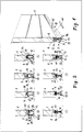
Figur 1 eine perspektivische Ansicht auf die Stirn- bzw. vertikale Querschnittsseite des untersten Paneeles eines über Kopf geführtbewegbaren Sektionaltorblattes 1;Figur 2 eine Teilansicht auf den vertikalen Querschnit eines unteren Bereiches des unteren Paneels gemäßFigur 1 mit acht unterschiedlichen Ausführungen der Dichtung nebst Dichtungsleiste in Anpassung an zwei unterschiedlich gestaltete Stirnwandungen der im Schließzustand unteren Kante des untersten Paneels.
- 1 shows a perspective view of the end or vertical cross-sectional side of the bottom panel of a
sectional door leaf 1 which can be moved overhead; - 2 shows a partial view of the vertical cross section of a lower region of the lower panel according to FIG. 1 with eight different designs of the seal and sealing strip in adaptation to two differently designed end walls of the lower edge of the lower panel when closed.
Das insgesamt mit 1 bezeichnete Torblatt bzw. unterste Torblattpaneel weist an seiner Unterkante 2 eine insgesamt mit 3 bezeichnete Dichtung auf, die mittels einer Halteleiste 4 bzw. 5 (Figur 2/8) an der unteren Stirnwandung 8 der Unterkante 2 des Paneels 1 festbelegt ist. Zu diesem Zwecke weist die Dichtung - eine Festlegeasubildung 6 bzw. 7 (Figur 2/8) auf, die in die Halteleiste eingreift. Sowohl die Dichtung und damit die Festlegeausbildung als auch die Halteleiste sind als Profile hergestellt, und zwar die Dichtung als Gummprofil und die Halteleiste als Metall- insbesondere Aluminiumprofil, so daß sich die Festlegeausbildung in die Halteleiste einschieben bzw. eindrücken läßt. In einer ersten bevorzugten Ausführungsform - Figur 1 und Figur 2/1 bis 7 ist die Halteleiste im Querschnitt C-förmig ausgebildet, jedenfalls was den Eingriffsbereich mit der Festlegeausbildung der Dichtung anbelangt, und zwar mit dem Öffnungsspalt zwischen den freien Schenkeln des C-Profils nach unten gerichtet. In diese Öffnung der Halteleiste greift der Steg einer T- bzw. I-querschnittsförmigen Festlegeausbildung 6 der Dichtung ein, wie dies die entsprechenden Figuren erkennen lassen, derart nämlich, daß die frei endenden Schenkel von dem oberen Querbalken des T- bzw. I-förmigen Profilquerschnittes der Festlegeausbildung hintergriffen werden. In anderer Ausgestaltung weist die Halteleiste 5 zwei zur Außenseite und Innenseite des Torblattes hin seitlich offene Nuten auf, in die Eingreifwulste 7 eingedrückt sind, die an nach oben offen ausgebildeten Seitenwandungen 20 eines Dichtungsprofils ausgebildet sind, wie es aus Figur 2/8 hervorgeht.The door leaf or the bottom door leaf panel, designated overall by 1, has on its lower edge 2 a seal designated overall by 3, which is fixed to the
Eine erste Ausführungsform der Dichtung ist in Figur 1 und den Figuren 2/1 und 2/3 gezeigt. Die Dichtung weist dabei zwischen der Festlegeausbildung 6 und einem dem Boden zu gerichteten Hohlprofil 12 einen Stegabschnitt 10 auf, der sich über eine gewisse vertikale Höhe reichend parallel zur Unterkante 2 des Torblattes 1 erstreckt. Das Hohlprofil 12 kann zunächst allgemein als Hohlwulstabschnitt 9 angesehen werden, soll im nahmen dieses Ausführungsbeispieles jedoch zusätzlich die Funktion einer Ausgestaltung der Dichtung als Unfallverhütungsleiste aufzeigen, dergestalt, daß bei Auftreffen der Dichtung auf ein Hindernis im Zuge der Bewegung des Torblattes durch Verformung des Hohlprofils 12 ein entsprechendes Notsignal ausgelöst wird, sei es durch Auslösen einer Druckwelle, Störung einer pyhsikalischen Größe, die sich entlang des Hohlraumes des Hohlprofils 12 ersteckt, woraufhin die Bewegung des Torblattes unterbrochen bzw. hinsichtlich Ihrer Richtung umgekehrt wird.A first embodiment of the seal is shown in Figure 1 and Figures 2/1 and 2/3. The seal has one between the
In diesem Fall befinden sich die Lüftungsöffnungen 14, vorzugsweise in Gestalt einer sich in Richtung parallel zur Unterkante 2 des Torblattes 1 ersteckenden Reihe von Langlochöffnungen ausgebildet, in dem Stegabschnitt 10 des Dichtungsprofils.In this case, the
Um eine windabweisende dichtende Anlage auf dem Boden bzw. einem bodenseitigen Zargenabschnitt sicherzustellen, wenn sich das Torblatt in der Schließstellung befindet, sind im bodennahen Bereich des Dichtungsprofiles vorzugsweise außen wie innenseitig Dichtungslippen 13 ausgeformt, wie dies die Figuren wiedergeben. Aufgrund dieser Dichtungslippen wird der Übertritt von Staub, Flüssigkeit oder dergleichen gehemmt. Um die Belüftungsöffnungen 14 gegen Feuchtigkeitsübertritt, insbesondere bei entsprechend schräg einfallendem Schlagregen zu schützen, können Abschirmungen 15 vorgesehen sein, die vorzugsweise aus dem Bereich der Festlegeausbildung 6 nach unten hin abragend ausgebildet sind und die Belüftungsöffnungen mit Abstand von deren Mündungen abdecken, so daß - wie in den Figuren mittels punktierter Pfeildarstellung angedeutet - der Luftübertritt durch die Belüftungsöffnungen 14 insoweit nicht behindert ist.In order to ensure a wind-repellent sealing system on the floor or a frame-side frame section when the door leaf is in the closed position, sealing
In den Beispielen gemäß Figur 2/2 und 4 ist die Dichtung von der Festlegeausbildung 6 an abwärts gesehen - hier immer der Schließzustand des Torblattes unterstellt - als einwandiger Lappen 11 ausgebildet, der in Dichtungslippen 13 übergeht und in welchem die Belüftungsöffnungen 14 befinden.In the examples according to FIGS. 2/2 and 4, the seal is seen from the
In den Beispielen nach den Figuren 2/5 bis 7 weist die Dichtung 3 einen Hohlwulstabschnitt 9 auf, der unmittelbar im Anschluß an die Festlegeausbildung 6 ausgeformt ist, so daß ein Bereich der Oberseite des Hohlwulstabschnittes 9 den unteren Querbalken der im Querschnitt doppel-T-förmigen bzw. anders ausgedrückt I-förmigen Festlegeausbildung zur Verfügung stellt. Gemäß Figur 2/5 sind die Belüftungsöffnungen 14 - vorzugsweise an senkrecht zur Torblattebene gesehen gegenüberliegenden Stellen - in den beiden Seitenwandungen des Hohlwulstabschnittes 9 vorgesehen. Dabei kann gemäß Figur 2/6 im bodennahen Bereich des Hohlwulstes ein gesondertes Hohlprofil 12 vorgesehen sein, wie es der Ausbildung einer Unfallverhütungsleisteneinrichtung dienlich ist. Figur 2/5 zeigt darüber hinaus ein Gitter oder Sieb 17, das in den Hohlwulstabschnitt 9 derart eingelegt ist, daß die Belüftungsöffnungen 14 gitter- bzw. siebförmig und damit luftdurchlässig übergriffen sind, so daß gröber Partikel unter Windeinfluß und/oder Insekten und je nach Größenordnung der Öffnungen Kleintiere die Lüftungsöffnungen nicht passieren können.In the examples according to FIGS. 2/5 to 7, the
Figur 2/7 zeigt eine Dichtung 3, die von der Unterkante 2 des Torblattes 1 aus nach unten gesehen Lüftungsöffnungen in Form von Aussparungen 16 aufweist, die in über die horizontale Erstreckung der Dichtung 3 gesehen regelmäßigen Abständen unter Durchtrennung der Festlegeausbildung 6 bis in den oberen Seitenwandungsbereich des Hohlwulstabschnittes 9 geführt sind. Wie die übrigen Belüftungsöffnungen auch lassen sich solche Aussparungen in die gummielastische Eigenschaften aufweisende Dichtung einbringen, insbesondere nachdem die Dichtung als Profil durch extrudieren herpestellt worden ist.Figure 2/7 shows a
Das Beispiel gemäß Figur 2/8 weicht insoweit von den übrigen Beispielen gemäß Figur 2 ab, als die Halteleiste 5 mit zwei sich außen und innenseitig öffnenden Nuten 21 versehen ist, in welche Eingreifwulste 22 des gummiarten Dichtungsprofils eingedrückt sind, die aufeinander zu gerichtet an den Innenseiten zweier Seitenwandungen vorgesehen sind. Die Seitenwandungen des Dichtungsprofils spalten sich in Richtung auf den Boden gesehen, wobei die jeweils nach außerhalb des torblattes gerichteten Spaltbereiche Dichtungslippen 13 bilden, während die nach innen aufeinander zu gerichteten Spaltbereiche in ein Hohlprofil 12 übergehen.The example according to FIG. 2/8 differs from the other examples according to FIG. 2 in that the
Wie die Figuren 1 und 2/1 erkennen lassen, kann das Dichtungsprofil vorbereitend derart ausgebildet sein, daß der durch die Belüftungsöffnungen gebildete Öffnungsquerschnitt wahlweise einstellbar ist. Unter Hinweis auf Figur 1 kann dies dadurch geschehen, daß die jeweils betroffene Dichtungswandung hinsichtlich der Umfangsberandung der Belüftungsöffnungen nur teilausgestanzt angeliefert wird, wo daß beispielsweise die innerhalb der Berandung liegenden Materialteile nur in Eckbereichen mit der betoffenen Dichtungswandung zsuammenhängen. Am Einsatzort kann dann durch Ausbrechen dieser von der Berandung umgriffenen Werkstoffteile die Anzahl der Öffnungen bestimmt werden, die der Belüftung dienen sollen. Nach dem Beispiel gemäß Figur 2/1 sind die dort im Stegabschnitt 10 vorgesehenen Belüftungsöffnungen 14 werksseitig durch einen oder - beidseitig - zwei Klebestreifen 19 abgedeckt, die am Einsatzort des Torblattes in beliebiger Größenordnung entfernt werden können, so daß auch hier der Gesamtquerschnitt der freigelegten Belüftungsöffnungen bestimmbar ist.As can be seen in FIGS. 1 and 2/1, the sealing profile can be designed in such a way that the opening cross-section formed by the ventilation openings can be optionally adjusted. With reference to Figure 1, this can be done in that the respective affected sealing wall is delivered only partially punched out with respect to the circumferential edge of the ventilation openings, where, for example, the material parts lying within the boundary only relate to the affected sealing wall in corner areas. On site, the number of openings that are to serve for ventilation can then be determined by breaking out these parts of the material encompassed by the edge. According to the example according to FIG. 2/1, the
Wie die Figuren erkennen lassen, ist die Gestaltung der Dichtung 3 insoweit unabhängig von der Querschnittskontur der nach unten gerichteten Stirnwandung 8 der Unterkante 2 des Torblattes 1, als eine entsprechende Anpassung an diese Kontur mit Hilfe der Halteleisten 4 bzw. 5 getroffen ist. Die Figuren 1 und 2/1,2 und 6 zeigen eine Querschnittskontur dieser unteren Stirnwandung 8, wie sie bei Paneelen auftritt, die in ihrem Anlenkungsbereich untereinander in keiner Stellung entlang ihrer Bewegungsbahn den Eingriff von Fingern zulassen. Aus Gründen einer billigen Fertigung werden für das gesamte Torblatt nur gleichgestaltete Paneele verwendet, so daß die der Unterkante zugeordnete Stirnwandung 8 entsprechend der Fugengestalt zwischen den Paneelen ausgebildet ist. Durch entsprechende Auswölbung der Halteleiste wird dieser Formgebung der Stirnwandung 8 im Bereich der Unterkante des Torblattes 1 Rechnung getragen. Die übrigen Beispiele nach den Figuren 2/3, 4,7 und 8 zeigen eine gestuft ausgebildete untere Stirnwandung 8, wie sie bei einer anderen Paneelformgebung bekannt ist. Hier fängt die Halteleiste diese unterschiedliche Formgebung durch eine flachere Bauart - beispielsweise im Querschnitt C-förmig - auf, wie dies die Figuren zeigen, auf die im übrigen insgesamt ausdrücklich Bezug genommen wird.As can be seen from the figures, the design of the
Claims (15)
dadurch gekennzeichnet,
daß die Belüftungsöffnungen (14) in der Dichtung (3), diese durchgreifend, vorgesehen sind.Door leaf, in particular one-part or multi-part door leaf that can be moved overhead, preferably made of slats, which consist of a sheet metal jacket foamed with plastic, for example polyurethane, which has ventilation openings for air transfer between the one on the outside of the door leaf and the one on the door leaf. On the other hand, the adjacent space is provided and its door leaf edge, which points downward in the closed position, has a seal, in particular including a deformable hollow bead, flap or the like,
characterized,
that the ventilation openings (14) in the seal (3), these are provided.
dadurch gekennzeichnet,
daß die Dichtung (3) als Strangprofil ausgebildet ist, in welches die Belüftungsöffnungen (14) eingebracht, insbesondere eingestanzt, sind.Door leaf according to claim 1,
characterized by
that the seal (3) is designed as an extruded profile, in which the ventilation openings (14) are introduced, in particular stamped.
dadurch gekennzeichnet,
daß die Dichtung (3) über eine - insbesondere leistenförmige - Festlegeausbildung (6; 7) in eine Halteleiste (4; 5) eingreift, die an der Unterkante (2) des Torblattes (1) befestigt ist.Door leaf according to claim 1 or 2,
characterized by
that the seal (3) engages in a retaining strip (4; 5), which is fastened to the lower edge (2) of the door leaf (1) via a - in particular strip-shaped - fixing formation (6; 7).
dadurch gekennzeichnet,
daß die Dichtung (3) einen Hohlwulstabschnitt (9) mit einem unmittelbar daran ausgebildeten Festlegeprofilabschnitt (6; 7) aufweist.Door leaf according to one of claims 1 to 3,
characterized by
that the seal (3) has a hollow bead section (9) with a fixing profile section (6; 7) formed directly thereon.
dadurch gekennzeichnet,
daß die Dichtung (3) einen zwischen einem Hohlwulst bzw. Hohlprofil (9 und/oder 12) und einer - insbesondere I-förmigen Festlegeausbildung (6) gelegenen Stegabschnitt (10) aufweist.Door leaf according to one of claims 1 to 3,
characterized by
that the seal (3) has a web portion (10) located between a hollow bead or hollow profile (9 and / or 12) and a - in particular I-shaped fixing formation (6).
dadurch gekennzeichnet,
daß die Dichtung (3) einen Lappen (11) umfaßt, der sich von einer Festlegeausbildung (6) in Schließstellung bis zum Boden bzw. einer Bodenzarge erstreckt.Door leaf according to one of claims 1 to 3,
characterized by
that the seal (3) comprises a tab (11) which extends from a fixing formation (6) in the closed position to the bottom or a bottom frame.
dadurch gekennzeichnet,
daß die Dichtung (3) ein - insbesondere im Querschnitt keisringförmiges - Hohlprofil (12) aufweist, das als Teil einer Sicherheitsleisteneinrichtung ausgebildet ist, die die Torblattbewegung bei Auftreffen der Unterkante (2) mit der Dichtung (3) auf ein Hindernis beeinflußt.Door leaf according to one of claims 1 to 5,
characterized by
that the seal (3) has a hollow profile (12), in particular in the form of a circular ring, which is designed as part of a safety strip device which influences the movement of the door leaf when the lower edge (2) meets the seal (3) on an obstacle.
dadurch gekennzeichnet,
daß die Dichtung (3) - vorzugsweise außen- und innenseitig des Torblattes (1) - im Schließzustand an dem Boden angreifende Dichtungslippen (13) aufweist.Door leaf according to one of claims 1 to 7,
characterized by
that the seal (3) - preferably on the outside and inside of the door leaf (1) - has sealing lips (13) engaging on the bottom in the closed state.
dadurch gekennzeichnet,
daß die Belüftungsöffnungen (14) als eine Reihe von Langlöchern ausgebildet sind, die sich parallel zur Unterkante (2) des Torblattes (1) erstreckt und die Wandungen des Hohlwulstes (9), den Stegabschnitt (10) bzw. den Lappen (11) durchgreift.Door leaf according to one of claims 1 to 8,
characterized by
that the ventilation openings (14) are designed as a series of elongated holes which extend parallel to the lower edge (2) of the door leaf (1) and the walls of the hollow bead (9), the web section (10) or the tab (11) passes through.
dadurch gekennzeichnet,
daß die Belüftungsöffnungen (14) von an der Dichtung (3), insbesondere an der Festlegeausbildung (6), aus geformten Abschirmungen (15) gegen Durchtritt von Schlagregen oder dergleichen Beeinflussungen geschützt sind.Door leaf according to one of claims 1 to 9,
characterized by
that the ventilation openings (14) on the seal (3), in particular on the fixing formation (6), of molded shields (15) are protected against the passage of driving rain or the like.
dadurch gekennzeichnet,
daß die Belüftungsöffnungen (14) durch von der Seite der Torunterkante (2) her eingebrachte, über die Festlegeausbildungen (6) hinausreichende Aussparungen (16) gebildet sind, die vorzugsweise mit gleichem Abstand voneinander in Längsrichtung der Dichtung (3) aufeinanderfolgend ausgebildet sind.Door leaf according to one of claims 1 to 8,
characterized by
that the ventilation openings (14) are formed by recesses (16) made from the side of the bottom edge of the door (2) and extending beyond the fixing formations (6), which are preferably formed in succession with the same distance from one another in the longitudinal direction of the seal (3).
dadurch gekennzeichnet,
daß die Belüftungsöffnungen (14) durch ein Gitter oder Sieb (17) luftdurchlässig abgedeckt sind, bei Anordnung der Belüftungsöffnungen (14) in den Wandungen eines Hohlwulstes (9) insbesondere durch ein in dieses eingesetztes netzförmiges Gebilde, beispielsweise aus Draht oder Kunststoff.Door leaf according to one of claims 1 to 11,
characterized by
that the ventilation openings (14) are covered with air through a grid or sieve (17), when the ventilation openings (14) are arranged in the walls of a hollow bead (9), in particular through a net-shaped structure inserted therein, for example made of wire or plastic.
dadurch gekennzeichnet,
daß die Belüftungsöffnungen (14) im fertigen Dichtungsprofil (3) nur teilausgestanzt und wahlweise am Betriebsort entfernbar sind.Door leaf according to one of claims 1 to 12,
characterized by
that the ventilation openings (14) in the finished sealing profile (3) are only partially punched out and can optionally be removed at the operating location.
dadurch gekennzeichnet,
daß die Belüftungsöffnungen (14) im fertigen Dichtungsprofil (3) völlig ausgestanzt und mittels eines wahlweise abziehbaren Klebestreifens (19) abgedeckt sind.Door leaf according to one of claims 1 to 12,
characterized by
that the ventilation openings (14) are completely punched out in the finished sealing profile (3) and by means of an optionally removable adhesive strip (19) are covered.
dadurch gekennzeichnet,
daß die als Profil ausgebildete Halteleiste (4; 5) an die Kontur der Stirnwandung (8) der Unterkante (2) des aus übereinstimmenden Paneelen, die beispielsweise während des gesamten Bewegungsablaufes gegen einen Fingereingriff geschützt insoweit ineinandergreifen, angepaßt ist und eine nach unten geöffnete C-Querschnittsform zur Aufnahme einer T- oder I-förmigen Festlegeausbildung (6) aufweist oder eine zur Torblattinnenseit eund eine zur Torblattaußenseite geöffnete Aufnahmenut (21) aufweist, in die Eingreifwulste (22) der Dichtung (3) eingedrückt sind, die an nach oben offen auslaufenden Seitenwandungen (20) der Dichtung (3) jeweils nach innen vorspringend ausgeformt sind.Door leaf according to one of claims 1 to 14,
characterized by
that the retaining strip (4; 5) designed as a profile is adapted to the contour of the end wall (8) of the lower edge (2) of the matching panels, which, for example, are protected against finger engagement during the entire movement sequence, and is adapted to a downwardly open C - Has a cross-sectional shape for receiving a T-shaped or I-shaped fixing formation (6) or has a receiving groove (21) open to the inside of the door leaf and a receiving groove (21) open to the outside of the door leaf, into which engagement beads (22) of the seal (3) are pressed, which are open at the top running out side walls (20) of the seal (3) are each formed inwardly projecting.
Applications Claiming Priority (2)
| Application Number | Priority Date | Filing Date | Title |
|---|---|---|---|
| DE4101013 | 1991-01-15 | ||
| DE4101013A DE4101013A1 (en) | 1991-01-15 | 1991-01-15 | DOOR LEAF WITH VENTILATION OPENINGS |
Publications (2)
| Publication Number | Publication Date |
|---|---|
| EP0497134A1 true EP0497134A1 (en) | 1992-08-05 |
| EP0497134B1 EP0497134B1 (en) | 1994-06-01 |
Family
ID=6423060
Family Applications (1)
| Application Number | Title | Priority Date | Filing Date |
|---|---|---|---|
| EP92100497A Expired - Lifetime EP0497134B1 (en) | 1991-01-15 | 1992-01-14 | Gate leaf with aerating openings |
Country Status (7)
| Country | Link |
|---|---|
| EP (1) | EP0497134B1 (en) |
| AT (1) | ATE106495T1 (en) |
| DE (2) | DE4101013A1 (en) |
| DK (1) | DK0497134T3 (en) |
| ES (1) | ES2054510T3 (en) |
| FI (1) | FI98752C (en) |
| NO (1) | NO180729C (en) |
Cited By (5)
| Publication number | Priority date | Publication date | Assignee | Title |
|---|---|---|---|---|
| EP0810345A2 (en) * | 1996-05-30 | 1997-12-03 | Hörmann Kg Dissen | Sealing profile for a door leaf |
| EP1498569A1 (en) * | 2003-07-17 | 2005-01-19 | Planet GDZ AG | Door seal |
| DE102005045970A1 (en) * | 2005-09-26 | 2007-03-29 | Hörmann KG Brockhagen | Door for use in e.g. garage, has door leaf, and locking arrangement operable for locking door leaf in ventilation position, which is arranged between closing position and opening position |
| WO2008043859A2 (en) * | 2006-10-13 | 2008-04-17 | Liexco S.A. | Door with closing profile and integrated ventilation |
| US8850747B2 (en) | 2006-10-13 | 2014-10-07 | Liexco, S.A. | Door with closing profile and integrated ventilation |
Families Citing this family (4)
| Publication number | Priority date | Publication date | Assignee | Title |
|---|---|---|---|---|
| CH691188A5 (en) * | 1995-11-20 | 2001-05-15 | Hesco Schweiz Ag | Door with ventilation device. |
| DE19610428C2 (en) * | 1996-03-16 | 2000-07-06 | Huels Troisdorf | Ventilated window |
| DE10021656B4 (en) * | 2000-05-04 | 2017-05-24 | PAN-DUR Holding GmbH & Co. KG | Rollo facility |
| DE102016008308A1 (en) * | 2016-07-06 | 2018-01-11 | Hörmann KG Brockhagen | sectional |
Citations (2)
| Publication number | Priority date | Publication date | Assignee | Title |
|---|---|---|---|---|
| CH429103A (en) * | 1964-08-05 | 1967-01-31 | Hofeto Maschinen Und Stahlbau | Garage door |
| DE8601985U1 (en) * | 1986-01-27 | 1987-05-27 | Hoermann Kg Brockhagen, 4803 Steinhagen, De |
Family Cites Families (3)
| Publication number | Priority date | Publication date | Assignee | Title |
|---|---|---|---|---|
| DE3503314A1 (en) * | 1985-01-31 | 1986-08-07 | Deventer Profile GmbH & Co KG, 1000 Berlin | Strand-shaped profile seal made of elastic material |
| DE8707959U1 (en) * | 1986-06-13 | 1987-10-15 | Exte-Extrudertechnik Gmbh, 5272 Wipperfuerth, De | |
| DE8623864U1 (en) * | 1986-09-05 | 1986-12-18 | Dynamit Nobel Ag, 5210 Troisdorf, De |
-
1991
- 1991-01-15 DE DE4101013A patent/DE4101013A1/en not_active Withdrawn
-
1992
- 1992-01-13 NO NO920150A patent/NO180729C/en unknown
- 1992-01-14 EP EP92100497A patent/EP0497134B1/en not_active Expired - Lifetime
- 1992-01-14 DK DK92100497.4T patent/DK0497134T3/en active
- 1992-01-14 FI FI920163A patent/FI98752C/en active IP Right Grant
- 1992-01-14 ES ES92100497T patent/ES2054510T3/en not_active Expired - Lifetime
- 1992-01-14 DE DE59200185T patent/DE59200185D1/en not_active Expired - Fee Related
- 1992-01-14 AT AT92100497T patent/ATE106495T1/en not_active IP Right Cessation
Patent Citations (2)
| Publication number | Priority date | Publication date | Assignee | Title |
|---|---|---|---|---|
| CH429103A (en) * | 1964-08-05 | 1967-01-31 | Hofeto Maschinen Und Stahlbau | Garage door |
| DE8601985U1 (en) * | 1986-01-27 | 1987-05-27 | Hoermann Kg Brockhagen, 4803 Steinhagen, De |
Cited By (9)
| Publication number | Priority date | Publication date | Assignee | Title |
|---|---|---|---|---|
| EP0810345A2 (en) * | 1996-05-30 | 1997-12-03 | Hörmann Kg Dissen | Sealing profile for a door leaf |
| EP0810345A3 (en) * | 1996-05-30 | 1999-03-17 | Hörmann Kg Dissen | Sealing profile for a door leaf |
| EP1498569A1 (en) * | 2003-07-17 | 2005-01-19 | Planet GDZ AG | Door seal |
| EP2267263A3 (en) * | 2003-07-17 | 2013-02-27 | Planet GDZ AG | Door seal |
| DE102005045970A1 (en) * | 2005-09-26 | 2007-03-29 | Hörmann KG Brockhagen | Door for use in e.g. garage, has door leaf, and locking arrangement operable for locking door leaf in ventilation position, which is arranged between closing position and opening position |
| WO2008043859A2 (en) * | 2006-10-13 | 2008-04-17 | Liexco S.A. | Door with closing profile and integrated ventilation |
| WO2008043859A3 (en) * | 2006-10-13 | 2008-08-21 | Liexco Sa | Door with closing profile and integrated ventilation |
| US8850747B2 (en) | 2006-10-13 | 2014-10-07 | Liexco, S.A. | Door with closing profile and integrated ventilation |
| US9234386B2 (en) | 2006-10-13 | 2016-01-12 | Rudi Dries | Door with closing profile and integrated ventilation |
Also Published As
| Publication number | Publication date |
|---|---|
| NO180729B (en) | 1997-02-24 |
| DE59200185D1 (en) | 1994-07-07 |
| NO920150L (en) | 1992-07-16 |
| NO180729C (en) | 1997-06-04 |
| FI98752C (en) | 1997-08-11 |
| EP0497134B1 (en) | 1994-06-01 |
| DK0497134T3 (en) | 1994-07-18 |
| ES2054510T3 (en) | 1994-08-01 |
| ATE106495T1 (en) | 1994-06-15 |
| NO920150D0 (en) | 1992-01-13 |
| FI98752B (en) | 1997-04-30 |
| FI920163A0 (en) | 1992-01-14 |
| DE4101013A1 (en) | 1992-07-16 |
| FI920163A (en) | 1992-07-16 |
Similar Documents
| Publication | Publication Date | Title |
|---|---|---|
| DE8521854U1 (en) | rolling gate | |
| EP3043017B1 (en) | Drainage system for door and window elements | |
| DE2758824C2 (en) | Door leaf for a folding or roller door | |
| EP0497134B1 (en) | Gate leaf with aerating openings | |
| EP1085162A2 (en) | Floor seal for a door | |
| DE19622796C2 (en) | Installation element for the closure of a building opening | |
| DE102016113085B4 (en) | Watertight sectional door device | |
| EP0647747A1 (en) | Supporting structure for the covering and/or the cladding of buildings | |
| DE4213146C2 (en) | Fan door | |
| EP0230998B1 (en) | Door leaf with ventilation openings | |
| DE2939028C2 (en) | Prefabricated wall element | |
| DE19613043A1 (en) | Post-rung construction | |
| WO1999013192A1 (en) | Plug-in fitting for hollow profiles | |
| DE10054029A1 (en) | Double-glazed door or window has L- or U-section profiles in frame glazing channels to give greater resistance to break-in | |
| EP4060157B1 (en) | Gate comprising a pass door | |
| AT412109B (en) | LOST FORMWORK | |
| EP0138771B1 (en) | Sealing device for a door without a threshold | |
| DE102020103603B4 (en) | Flood-resistant sectional door | |
| AT390300B (en) | ELASTIC SEALING PROFILE FOR WINDOWS OR THE LIKE ROOM LOCKING BODIES | |
| DE19615884A1 (en) | Roller shutter for house window | |
| EP1008700B1 (en) | Device comprising multiple pivotable lamellas | |
| EP1321620A2 (en) | Section for the door leaf of sectional doors | |
| DE4315644C2 (en) | Building window | |
| EP0450265B1 (en) | Edge lining for thin window sills | |
| DE102016115460B4 (en) | End strip for a roller shutter |
Legal Events
| Date | Code | Title | Description |
|---|---|---|---|
| PUAI | Public reference made under article 153(3) epc to a published international application that has entered the european phase |
Free format text: ORIGINAL CODE: 0009012 |
|
| AK | Designated contracting states |
Kind code of ref document: A1 Designated state(s): AT BE CH DE DK ES FR GB IT LI NL SE |
|
| 17P | Request for examination filed |
Effective date: 19930204 |
|
| 17Q | First examination report despatched |
Effective date: 19930816 |
|
| GRAA | (expected) grant |
Free format text: ORIGINAL CODE: 0009210 |
|
| AK | Designated contracting states |
Kind code of ref document: B1 Designated state(s): AT BE CH DE DK ES FR GB IT LI NL SE |
|
| REF | Corresponds to: |
Ref document number: 106495 Country of ref document: AT Date of ref document: 19940615 Kind code of ref document: T |
|
| ET | Fr: translation filed | ||
| REF | Corresponds to: |
Ref document number: 59200185 Country of ref document: DE Date of ref document: 19940707 |
|
| REG | Reference to a national code |
Ref country code: DK Ref legal event code: T3 |
|
| REG | Reference to a national code |
Ref country code: ES Ref legal event code: FG2A Ref document number: 2054510 Country of ref document: ES Kind code of ref document: T3 |
|
| GBT | Gb: translation of ep patent filed (gb section 77(6)(a)/1977) |
Effective date: 19940713 |
|
| ITF | It: translation for a ep patent filed |
Owner name: SOCIETA' ITALIANA BREVETTI S.P.A. |
|
| EAL | Se: european patent in force in sweden |
Ref document number: 92100497.4 |
|
| ITTA | It: last paid annual fee | ||
| PLBE | No opposition filed within time limit |
Free format text: ORIGINAL CODE: 0009261 |
|
| STAA | Information on the status of an ep patent application or granted ep patent |
Free format text: STATUS: NO OPPOSITION FILED WITHIN TIME LIMIT |
|
| 26N | No opposition filed | ||
| REG | Reference to a national code |
Ref country code: GB Ref legal event code: IF02 |
|
| PGFP | Annual fee paid to national office [announced via postgrant information from national office to epo] |
Ref country code: CH Payment date: 20041229 Year of fee payment: 14 |
|
| PGFP | Annual fee paid to national office [announced via postgrant information from national office to epo] |
Ref country code: GB Payment date: 20050113 Year of fee payment: 14 |
|
| PGFP | Annual fee paid to national office [announced via postgrant information from national office to epo] |
Ref country code: AT Payment date: 20050114 Year of fee payment: 14 |
|
| PGFP | Annual fee paid to national office [announced via postgrant information from national office to epo] |
Ref country code: DK Payment date: 20050117 Year of fee payment: 14 |
|
| PGFP | Annual fee paid to national office [announced via postgrant information from national office to epo] |
Ref country code: ES Payment date: 20050125 Year of fee payment: 14 |
|
| PGFP | Annual fee paid to national office [announced via postgrant information from national office to epo] |
Ref country code: BE Payment date: 20050131 Year of fee payment: 14 |
|
| PG25 | Lapsed in a contracting state [announced via postgrant information from national office to epo] |
Ref country code: AT Free format text: LAPSE BECAUSE OF NON-PAYMENT OF DUE FEES Effective date: 20060114 Ref country code: GB Free format text: LAPSE BECAUSE OF NON-PAYMENT OF DUE FEES Effective date: 20060114 |
|
| PG25 | Lapsed in a contracting state [announced via postgrant information from national office to epo] |
Ref country code: ES Free format text: LAPSE BECAUSE OF NON-PAYMENT OF DUE FEES Effective date: 20060116 |
|
| PG25 | Lapsed in a contracting state [announced via postgrant information from national office to epo] |
Ref country code: LI Free format text: LAPSE BECAUSE OF NON-PAYMENT OF DUE FEES Effective date: 20060131 Ref country code: BE Free format text: LAPSE BECAUSE OF NON-PAYMENT OF DUE FEES Effective date: 20060131 Ref country code: CH Free format text: LAPSE BECAUSE OF NON-PAYMENT OF DUE FEES Effective date: 20060131 Ref country code: DK Free format text: LAPSE BECAUSE OF NON-PAYMENT OF DUE FEES Effective date: 20060131 |
|
| REG | Reference to a national code |
Ref country code: DK Ref legal event code: EBP |
|
| REG | Reference to a national code |
Ref country code: CH Ref legal event code: PL |
|
| GBPC | Gb: european patent ceased through non-payment of renewal fee |
Effective date: 20060114 |
|
| REG | Reference to a national code |
Ref country code: ES Ref legal event code: FD2A Effective date: 20060116 |
|
| BERE | Be: lapsed |
Owner name: *HORMANN K.G. BROCKHAGEN Effective date: 20060131 |
|
| PGFP | Annual fee paid to national office [announced via postgrant information from national office to epo] |
Ref country code: NL Payment date: 20090131 Year of fee payment: 18 |
|
| PGFP | Annual fee paid to national office [announced via postgrant information from national office to epo] |
Ref country code: IT Payment date: 20090122 Year of fee payment: 18 Ref country code: DE Payment date: 20090325 Year of fee payment: 18 Ref country code: SE Payment date: 20090115 Year of fee payment: 18 |
|
| PGFP | Annual fee paid to national office [announced via postgrant information from national office to epo] |
Ref country code: FR Payment date: 20090129 Year of fee payment: 18 |
|
| REG | Reference to a national code |
Ref country code: NL Ref legal event code: V1 Effective date: 20100801 |
|
| EUG | Se: european patent has lapsed | ||
| REG | Reference to a national code |
Ref country code: FR Ref legal event code: ST Effective date: 20100930 |
|
| PG25 | Lapsed in a contracting state [announced via postgrant information from national office to epo] |
Ref country code: FR Free format text: LAPSE BECAUSE OF NON-PAYMENT OF DUE FEES Effective date: 20100201 Ref country code: NL Free format text: LAPSE BECAUSE OF NON-PAYMENT OF DUE FEES Effective date: 20100801 |
|
| PG25 | Lapsed in a contracting state [announced via postgrant information from national office to epo] |
Ref country code: DE Free format text: LAPSE BECAUSE OF NON-PAYMENT OF DUE FEES Effective date: 20100803 |
|
| PG25 | Lapsed in a contracting state [announced via postgrant information from national office to epo] |
Ref country code: IT Free format text: LAPSE BECAUSE OF NON-PAYMENT OF DUE FEES Effective date: 20100114 |
|
| PG25 | Lapsed in a contracting state [announced via postgrant information from national office to epo] |
Ref country code: SE Free format text: LAPSE BECAUSE OF NON-PAYMENT OF DUE FEES Effective date: 20100115 |