EP0647747A1 - Supporting structure for the covering and/or the cladding of buildings - Google Patents
Supporting structure for the covering and/or the cladding of buildings Download PDFInfo
- Publication number
- EP0647747A1 EP0647747A1 EP94115314A EP94115314A EP0647747A1 EP 0647747 A1 EP0647747 A1 EP 0647747A1 EP 94115314 A EP94115314 A EP 94115314A EP 94115314 A EP94115314 A EP 94115314A EP 0647747 A1 EP0647747 A1 EP 0647747A1
- Authority
- EP
- European Patent Office
- Prior art keywords
- support
- profile
- structure according
- flange
- rail
- Prior art date
- Legal status (The legal status is an assumption and is not a legal conclusion. Google has not performed a legal analysis and makes no representation as to the accuracy of the status listed.)
- Granted
Links
Images


Classifications
-
- E—FIXED CONSTRUCTIONS
- E04—BUILDING
- E04C—STRUCTURAL ELEMENTS; BUILDING MATERIALS
- E04C3/00—Structural elongated elements designed for load-supporting
- E04C3/02—Joists; Girders, trusses, or trusslike structures, e.g. prefabricated; Lintels; Transoms; Braces
- E04C3/04—Joists; Girders, trusses, or trusslike structures, e.g. prefabricated; Lintels; Transoms; Braces of metal
- E04C3/06—Joists; Girders, trusses, or trusslike structures, e.g. prefabricated; Lintels; Transoms; Braces of metal with substantially solid, i.e. unapertured, web
- E04C3/07—Joists; Girders, trusses, or trusslike structures, e.g. prefabricated; Lintels; Transoms; Braces of metal with substantially solid, i.e. unapertured, web at least partly of bent or otherwise deformed strip- or sheet-like material
-
- E—FIXED CONSTRUCTIONS
- E04—BUILDING
- E04B—GENERAL BUILDING CONSTRUCTIONS; WALLS, e.g. PARTITIONS; ROOFS; FLOORS; CEILINGS; INSULATION OR OTHER PROTECTION OF BUILDINGS
- E04B7/00—Roofs; Roof construction with regard to insulation
- E04B7/02—Roofs; Roof construction with regard to insulation with plane sloping surfaces, e.g. saddle roofs
-
- E—FIXED CONSTRUCTIONS
- E04—BUILDING
- E04D—ROOF COVERINGS; SKY-LIGHTS; GUTTERS; ROOF-WORKING TOOLS
- E04D3/00—Roof covering by making use of flat or curved slabs or stiff sheets
- E04D3/36—Connecting; Fastening
- E04D3/3607—Connecting; Fastening the fastening means comprising spacer means adapted to the shape of the profiled roof covering
-
- E—FIXED CONSTRUCTIONS
- E04—BUILDING
- E04D—ROOF COVERINGS; SKY-LIGHTS; GUTTERS; ROOF-WORKING TOOLS
- E04D3/00—Roof covering by making use of flat or curved slabs or stiff sheets
- E04D3/36—Connecting; Fastening
- E04D3/361—Connecting; Fastening by specially-profiled marginal portions of the slabs or sheets
- E04D3/362—Connecting; Fastening by specially-profiled marginal portions of the slabs or sheets by locking the edge of one slab or sheet within the profiled marginal portion of the adjacent slab or sheet, e.g. using separate connecting elements
-
- E—FIXED CONSTRUCTIONS
- E04—BUILDING
- E04C—STRUCTURAL ELEMENTS; BUILDING MATERIALS
- E04C3/00—Structural elongated elements designed for load-supporting
- E04C3/02—Joists; Girders, trusses, or trusslike structures, e.g. prefabricated; Lintels; Transoms; Braces
- E04C3/04—Joists; Girders, trusses, or trusslike structures, e.g. prefabricated; Lintels; Transoms; Braces of metal
- E04C2003/0404—Joists; Girders, trusses, or trusslike structures, e.g. prefabricated; Lintels; Transoms; Braces of metal beams, girders, or joists characterised by cross-sectional aspects
- E04C2003/0408—Joists; Girders, trusses, or trusslike structures, e.g. prefabricated; Lintels; Transoms; Braces of metal beams, girders, or joists characterised by cross-sectional aspects characterised by assembly or the cross-section
- E04C2003/0421—Joists; Girders, trusses, or trusslike structures, e.g. prefabricated; Lintels; Transoms; Braces of metal beams, girders, or joists characterised by cross-sectional aspects characterised by assembly or the cross-section comprising one single unitary part
-
- E—FIXED CONSTRUCTIONS
- E04—BUILDING
- E04C—STRUCTURAL ELEMENTS; BUILDING MATERIALS
- E04C3/00—Structural elongated elements designed for load-supporting
- E04C3/02—Joists; Girders, trusses, or trusslike structures, e.g. prefabricated; Lintels; Transoms; Braces
- E04C3/04—Joists; Girders, trusses, or trusslike structures, e.g. prefabricated; Lintels; Transoms; Braces of metal
- E04C2003/0404—Joists; Girders, trusses, or trusslike structures, e.g. prefabricated; Lintels; Transoms; Braces of metal beams, girders, or joists characterised by cross-sectional aspects
- E04C2003/0426—Joists; Girders, trusses, or trusslike structures, e.g. prefabricated; Lintels; Transoms; Braces of metal beams, girders, or joists characterised by cross-sectional aspects characterised by material distribution in cross section
- E04C2003/0434—Joists; Girders, trusses, or trusslike structures, e.g. prefabricated; Lintels; Transoms; Braces of metal beams, girders, or joists characterised by cross-sectional aspects characterised by material distribution in cross section the open cross-section free of enclosed cavities
-
- E—FIXED CONSTRUCTIONS
- E04—BUILDING
- E04C—STRUCTURAL ELEMENTS; BUILDING MATERIALS
- E04C3/00—Structural elongated elements designed for load-supporting
- E04C3/02—Joists; Girders, trusses, or trusslike structures, e.g. prefabricated; Lintels; Transoms; Braces
- E04C3/04—Joists; Girders, trusses, or trusslike structures, e.g. prefabricated; Lintels; Transoms; Braces of metal
- E04C2003/0404—Joists; Girders, trusses, or trusslike structures, e.g. prefabricated; Lintels; Transoms; Braces of metal beams, girders, or joists characterised by cross-sectional aspects
- E04C2003/0443—Joists; Girders, trusses, or trusslike structures, e.g. prefabricated; Lintels; Transoms; Braces of metal beams, girders, or joists characterised by cross-sectional aspects characterised by substantial shape of the cross-section
- E04C2003/0452—H- or I-shaped
-
- E—FIXED CONSTRUCTIONS
- E04—BUILDING
- E04C—STRUCTURAL ELEMENTS; BUILDING MATERIALS
- E04C3/00—Structural elongated elements designed for load-supporting
- E04C3/02—Joists; Girders, trusses, or trusslike structures, e.g. prefabricated; Lintels; Transoms; Braces
- E04C3/04—Joists; Girders, trusses, or trusslike structures, e.g. prefabricated; Lintels; Transoms; Braces of metal
- E04C2003/0404—Joists; Girders, trusses, or trusslike structures, e.g. prefabricated; Lintels; Transoms; Braces of metal beams, girders, or joists characterised by cross-sectional aspects
- E04C2003/0443—Joists; Girders, trusses, or trusslike structures, e.g. prefabricated; Lintels; Transoms; Braces of metal beams, girders, or joists characterised by cross-sectional aspects characterised by substantial shape of the cross-section
- E04C2003/046—L- or T-shaped
-
- E—FIXED CONSTRUCTIONS
- E04—BUILDING
- E04C—STRUCTURAL ELEMENTS; BUILDING MATERIALS
- E04C3/00—Structural elongated elements designed for load-supporting
- E04C3/02—Joists; Girders, trusses, or trusslike structures, e.g. prefabricated; Lintels; Transoms; Braces
- E04C3/04—Joists; Girders, trusses, or trusslike structures, e.g. prefabricated; Lintels; Transoms; Braces of metal
- E04C2003/0404—Joists; Girders, trusses, or trusslike structures, e.g. prefabricated; Lintels; Transoms; Braces of metal beams, girders, or joists characterised by cross-sectional aspects
- E04C2003/0443—Joists; Girders, trusses, or trusslike structures, e.g. prefabricated; Lintels; Transoms; Braces of metal beams, girders, or joists characterised by cross-sectional aspects characterised by substantial shape of the cross-section
- E04C2003/0473—U- or C-shaped
-
- E—FIXED CONSTRUCTIONS
- E04—BUILDING
- E04D—ROOF COVERINGS; SKY-LIGHTS; GUTTERS; ROOF-WORKING TOOLS
- E04D3/00—Roof covering by making use of flat or curved slabs or stiff sheets
- E04D3/36—Connecting; Fastening
- E04D3/361—Connecting; Fastening by specially-profiled marginal portions of the slabs or sheets
- E04D2003/3615—Separate fastening elements fixed to the roof structure and consisting of parts permitting relative movement to each other, e.g. for thermal expansion
Definitions
- the invention relates to a supporting structure for roofing and / or outer skin planking of buildings with a support arrangement fastened to the building and supporting and fastening elements attached to it in a projecting manner for connecting, load transfer and fixing the position of preferably metal, profiled planking sheeting with overlap strips on both sides, which act as profile overlaps or are formed as channel-like or bead-like, downwardly open, overlapping folds.
- profiled panels or profile planks are used, which are attached to a structure previously attached to the building.
- These profile sheets or planks have, for example, an essentially U-shaped cross section, the bottom of this U profile being able to be provided with ribs running in the longitudinal direction for reinforcement and the free ends of the side legs being rolled outwards, so that in each case a part-circular bead is formed forms.
- these beads surround each other or in another way trained overlaps of adjacent panels or planks mutually on the one hand and on the other hand also supporting and fastening elements which protrude from a supporting structure attached to the surface to be covered.
- Such profiled sheets or planks are used in very different widths and lengths. This has the advantage that transverse collisions with the risk of leaks can be avoided even on large surfaces; however, it also requires a structure that is as variable as possible and adaptable to the circumstances, in particular the supporting and fastening elements.
- DE 91 04 370.0 U1 shows such a supporting structure, which essentially consists of spaced-apart support rails and sliding elements on which the cladding sheets are supported.
- This displaceability is intended to solve the problem that the support elements can be set up at different distances between the overlap strips or beads of the individual planking sheets.
- the object of the present invention is to provide a structure of the type mentioned which can be varied and easily adapted for different applications and which is simple to manufacture and assemble; weight reduction is also sought.
- the support arrangement contains support rails attached to them by means of spacing supporting flanges and having two support rails which run at a distance from each other and run parallel to one another and are graspable on both sides, flat, continuous or interrupted longitudinal strips, onto which there are upstanding retaining clips provided with support profiles formed on their free ends , by means of profile guides whose longitudinal strips can be put on or pushed on under and around sliding webs.
- Such a sliding web preferably consists of a web plate and of side guide strips attached to it on both sides, for gripping and gripping under the longitudinal strips of the mounting rail, or of edging shaped into U-profile guides, and of at least one upstanding holding clip with a mounting profile directed parallel or transverse to the course of the mounting rail .
- the web plate of the sliding web can be provided in the center area with a reinforcing bead and the retaining clip, which stands up transversely or parallel to the course of the mounting rail, can be provided with a stiffening bead and with lateral guide strips flanged on both sides in a radius of curvature.
- its web plate is provided with one which is parallel to or transverse to the course of the mounting rail and which is angled in the lower region in relation to one another Retaining clip with support flanks and edging on both sides, shaped into profile guides.
- the support flanks also cause stiffening.
- the support profile of the holding clips essentially has the profile of a triangle with rounded corners and its side surfaces are provided with constrictions.
- the overlap bead of a profile panel or profile plank to be mounted can then advantageously overlap or encompass the supporting profile and come to rest on the supporting flanks resulting from the constrictions in the side surfaces. This creates a safe, resilient connection that is watertight against the ingress of moisture between adjacent profile panels or profile planks and the retaining clips.
- a support beam is connected to the web plate of the sliding web, which carries a clamping and support profile, which is designed as a box profile with at least two side faces pointing at an angle to one another and a flat head surface which is directed parallel or transversely to the course of the support rail , has constrictions on both sides merging into the side surfaces.
- the box profile can essentially have the shape of a pentagon standing on the top, the inclined side surfaces being connected upwards by the flat head surface, which has constrictions that run parallel or transversely to the course of the mounting rail and pass into the side surfaces on both sides.
- the transition areas between the constriction surfaces and the top surface on the one hand and the side surfaces on the other hand can be sharp-edged or connected with small radii.
- Such a support profile can be springily overlapped and overlapped by the correspondingly shaped overlap strips of the profile panels or profile planks to be assembled, so that a kind of push-button connection is created between the support profile and adjacent profile panels or planks, which is secure and resilient and tight against the ingress of moisture is and also compensates for temperature fluctuations.
- the sliding web has a double-leaf web plate, of which each of the opposing web plate wings is each provided with a pair of profile guides shaped to embrace and reach under the mounting rail, the directional extension of which pivoted relative to one another by an angle ⁇ between 30 ° and 60 ° and one of the pairs is attached to opposite protruding lugs; the multi-skin panels are connected by a raised clip.
- This last-described embodiment of the sliding bridge has the advantage that it can be pushed onto the carrier in two different, pivoted positions. If one of the opposing profile guides of the multi-skin sheet wings is in engagement with the mounting rail, the retaining clip is at right angles to the mounting rail; if the other opposing profile guides of the multi-skin sheet wings are engaged with the mounting rail, the retaining clip runs diagonally to the mounting rail. So it is possible, if the same parts are used, to run the profiled sheets or planks either at right angles or diagonally on a building surface.
- the sliding bars In practical use, the sliding bars must be fixed in their position on the mounting rail; this can generally be done by screwing, but also by jamming or pressing. In the last-mentioned embodiment of a sliding web, the fixation can also be achieved by hammer blows on the approach of the two multi-wall panel wings projecting above the mounting rail.
- the mounting rail with its longitudinal strips is connected to the carrier arrangement by a mounting flange with at least one floor mounting flange arranged at an angle to this. It can also be connected to a carrier arrangement by two spaced-apart support flanges, each with an associated base fastening flange arranged at an angle thereto.
- a double-T beam can also serve as the carrier arrangement, the upper flange of which acts as a mounting rail and the longitudinal strips on both sides and the lower flange of which forms the floor mounting flange.
- the mounting rail is formed from with its longitudinal strips from a flat, four-fold cut, which consists of a U-profile lying on the back and longitudinal strips spaced on both sides; the back of the U-profile is attached to the upper flange of a double-T beam, the lower flange of which forms the floor mounting flange.
- the support flange or the support flanges and the support rail with their longitudinal strips can also be produced from a flat sheet metal blank by folding.
- the mounting flange and the mounting rail can be folded in at a first right angle the upper region of the vertical support flange to the one horizontal longitudinal strip and by a second folding by 180 ° to the second horizontal longitudinal strip.
- the base mounting flange or flanges can also be formed from the sheet metal blank.
- the two longitudinal strips of the mounting rail formed by folding from a sheet metal blank are preferably provided with constrictions which can be encompassed and grasped on their outer edges by the sliding webs by means of their profile guides.
- transition areas between the constriction surfaces and the head surface forming the mounting rail with longitudinal strips on the one hand and the side surfaces forming the mounting rail on the other hand can be rounded or rounded with small radii.
- the different embodiments of the sliding webs can advantageously be used optionally with the different embodiments of the carrier arrangement, provided only the profile guides of the web plates are adapted to the longitudinal strips of the mounting rails. This results in possible variations according to different external conditions.
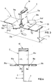
- a first right-angled folding at A1 in the upper area creates the support flange 2 and first the one horizontal longitudinal strip 26a of the mounting rail 26 and a second folding by 180 ° at A2 the second horizontal longitudinal strip 26b of the mounting rail 26.
- a further right-angled folding at A3 in the lower region of the support flange 2 results in the horizontal floor mounting flange 3 at a distance from the support rail 26.
- a sliding web B with holding clip 10 is shown in Fig. 1, which is also integrally formed from a sheet. Both longitudinal edges of the web plate 34 are flanged down to side guide strips 30 which fit onto the longitudinal strips 26a, 26b of the support rail 26 and encompass them when the sliding web B is pushed onto the carrier arrangement A. A reinforcing bead 17 is provided in the middle of the web plate 34.
- the holding clip 10 is bent vertically upward as a tab. The free end of this retaining clip 10 is formed into a support profile 40 which essentially has the profile of a triangle with rounded corners 41, 43 and is provided with constrictions 42 in the side surfaces.
- the support profile 40 is open on one side at the bottom and is springily gripped by the overlapping beads during the assembly of the above-mentioned profile panels or profile planks, so that a secure connection is achieved.
- a stiffening bead 39 is provided to stiffen the retaining clip 10.
- the holding clip 10 with the support profile 40 runs transversely to the carrier arrangement A.
- a sliding web C is shown, in which the holding clip 10a with the support profile 40 runs in the longitudinal direction of the carrier arrangement A.
- the outer edges of the web plate 34 are formed in the illustrated case by folds 35 to form U-profile guides 38, which e.g. fits onto the longitudinal strips 26a, 26b of the mounting rail 26 of a carrier arrangement A according to FIG. 1 or also of a differently designed carrier arrangement.
- the holding clip 10a according to FIG. 2 has two support flanks 29 which are angled relative to one another in its lower region.
- Fig. 3 shows another embodiment of the invention.
- the carrier arrangement A corresponds essentially to that of FIG. 1 with the difference that the support rail 26 is formed by the transverse flange of a T-profile.
- the sliding web E has a two-leaf web plate, on the opposing web plate wings 34a, 34b of which a pair of profile guides 30a, 30b are formed, which embrace the support rail 26 or its longitudinal strips 26a, 26b.
- the profile guides 30a, 30b of each web plate wing 34a, 34b are pivoted to each other at an angle ⁇ between 30 ° and 60 ° (see also FIG. 6).
- One of the profile guide pairs 30b is formed on opposite, protruding, angled projections 34a ', 34b' of the web plate wings 34a, 34b. As will be explained in more detail below, either one pair of profile guides 30a or the other 30b is in engagement with the mounting rail 26.
- the support flanks 29 of the holding clips 10a are drawn up by folding and are connected to one another, for example, by welding are and thus form the retaining clip 10a, the upper end of which is shaped into a support profile 40 according to FIGS. 1 and 2. 3, the support profile 40 can also be closed.
- FIG. 4 shows the end view of the arrangement according to FIG. 3.
- FIG. 3 shows an arrangement which consists of the same parts as that of FIG. 3, but with the difference that the holding clip 10a together with the support profile 40 extends to the support arrangement A at an angle of approximately 45 °.
- FIG. 5 shows an arrangement which consists of the same parts as that of FIG. 3, but with the difference that the holding clip 10a together with the support profile 40 extends to the support arrangement A at an angle of approximately 45 °.
- the sliding webs must be fixed in their position on the mounting rail, ie firmly connected to it; this can be done by screwing, but also by jamming or pressing. In the case of the special design of the sliding web E according to FIGS. 3 to 6, this can also be done by hammer blows on the part of the web plate wings 34a, 34b which projects above the mounting rail 26.
- FIG. 7 shows a carrier arrangement S which is formed by a double-T carrier 60.
- the lower flange of this double-T beam 60 serves as a floor mounting flange 3
- the upper flange 51 can either form the mounting rail 26 with the longitudinal strips 26a, 26b on both sides, as shown in FIG. 9, or it may be a flat one on it, as shown in FIG. 7
- the sheet metal blank can be fastened by four U-shaped sections with longitudinal strips 26a, 26b spaced on both sides, lying on the back 50.
- Fig. 8 shows a special embodiment of a sliding web D.
- a web plate 34 is bent at its two longitudinal edges downwards and inwards 35 or flanged to form the profile guides 38.
- a support beam 28 protrudes vertically upwards from the center line of the web plate 34
- Clamping and support profile 66 carries, which is designed as a box profile with at least two side surfaces 62 facing each other at an angle and a flat head surface 64; the top surface 64 has constrictions 63 which are directed parallel or transversely to the course of the mounting rails 26 and merge on both sides into the side surfaces 62. According to FIGS.
- the box profile essentially follows the shape of a pentagon standing on the top, the inclined side surfaces 62 being connected upwards by the flat head surface 64: this has the parallel or transverse direction of the support rail 26 on both sides constriction surfaces merging into the side surfaces 62.
- the transition regions 63, 65 between the constriction surfaces and the head surface 64 on the one hand and the side surfaces 62 on the other hand can be sharp-edged or rounded with small radii.
- Such a support profile 66 can be assembled Reach around and behind profile sheets or profile planks with their overlapping strips so that a secure pressure connection is given.
- FIG. 9 What can be seen is a carrier arrangement T with a double-T profile, the upper flange 51 of which directly forms the support rail 26.
- a sliding web D according to FIG. 8 is pushed onto the mounting rail 26.
- the connection or overlap area of two adjacent profile panels or profile planks P is also indicated.
- Each profile panel P is bent upward at an obtuse angle on its longitudinal side and then follows the one inwardly inclined side surface 62, of the constrictions 63 in question and the head surface 64 of the support profile 66.
- the side strips of the adjacent profile panels or profile planks P overlap and overlap or underlap one another; at the same time, they grip the supporting profile 66 together in a springy manner.
- FIG. 10 shows a further form of a carrier arrangement R, which is made from a sheet metal blank and has a trapezoidal shape that tapers upwards.
- the support rail 26 with its longitudinal strips 26a, 26b is also connected to the support arrangement R by two spaced-apart, inclined support flanges 52, each with an associated base fastening flange 53 arranged at an angle to it by a bend A3.
- the longitudinal strips 26a, 26b of the mounting rail 26 formed by folding from the sheet metal blank are provided with constrictions 54 on their outer edges, which can be encompassed and gripped by the sliding webs B, C, D or E with their profile guides 30 and 35, 38, respectively.
- the transition areas between the constriction surfaces, the longitudinal strips 26a, 26b of the mounting rail 26 and the mounting flanges 52 can be sharp-edged or rounded with small radii.
Abstract
Description
Die Erfindung betrifft ein Tragwerk für die Bedachung und/oder Aussenhaut-Beplankung von Gebäuden mit einer am Gebäude befestigten Trägeranordnung und an dieser abstehend angebrachten Trag- und Befestigungselementen zur Verbindung, Lastabtragung und Lagefixierung von vorzugsweise metallenen, profilierten Beplankungsbahnen mit beidseitigen Überlappungsstreifen, die als Profilüberlappungen oder als rinnen- oder wulstartige, nach unten offene, sich überlappende Umfalzungen ausgebildet sind.The invention relates to a supporting structure for roofing and / or outer skin planking of buildings with a support arrangement fastened to the building and supporting and fastening elements attached to it in a projecting manner for connecting, load transfer and fixing the position of preferably metal, profiled planking sheeting with overlap strips on both sides, which act as profile overlaps or are formed as channel-like or bead-like, downwardly open, overlapping folds.
Bei der Bedachung und Fassadenverkleidung von Gebäuden und insbesondere bei der Gebäudesanierung kommen Profiltafeln bzw. Profilplanken zur Anwendung, die an einem zuvor am Gebäude angebrachten Tragwerk befestigt werden. Diese Profiltafeln oder -planken haben beispielsweise einen im wesentlichen U-förmigen Querschnitt, wobei der Boden dieses U-Profils zur Versteifung mit in Längsrichtung verlaufenden Rippen versehen sein kann und die freien Enden der Seitenschenkel nach aussen gerollt sind, so dass sich jeweils ein teilkreisförmiger Wulst bildet. Bei der Montage umgreifen sich diese Wulste oder auch in anderer Weise ausgebildete Überlappungen benachbarter Tafeln oder Planken einerseits gegenseitig und andererseits auch Trag- und Befestigungselemente, die von einem auf der abzudeckenden Fläche angebrachten Tragwerk abstehen.In the roofing and facade cladding of buildings and especially in building renovation, profiled panels or profile planks are used, which are attached to a structure previously attached to the building. These profile sheets or planks have, for example, an essentially U-shaped cross section, the bottom of this U profile being able to be provided with ribs running in the longitudinal direction for reinforcement and the free ends of the side legs being rolled outwards, so that in each case a part-circular bead is formed forms. During assembly, these beads surround each other or in another way trained overlaps of adjacent panels or planks mutually on the one hand and on the other hand also supporting and fastening elements which protrude from a supporting structure attached to the surface to be covered.
Solche Profiltafeln oder -planken kommen in sehr unterschiedlichen Breiten und Längen zur Anwendung. Das hat den Vorteil, dass auch bei grossen Flächen Querstösse mit der Gefahr von Undichtigkeit vermieden werden können; es erfordert aber auch ein möglichst variierbares, den Gegebenheiten anpassbares Tragwerk, insbesondere der Trag- und Befestigungselemente.Such profiled sheets or planks are used in very different widths and lengths. This has the advantage that transverse collisions with the risk of leaks can be avoided even on large surfaces; however, it also requires a structure that is as variable as possible and adaptable to the circumstances, in particular the supporting and fastening elements.
Tragwerke der eingangs genannten Art sind bekannt. Beispielsweise zeigt die DE 91 04 370.0 U1 ein derartiges Tragwerk, welches im wesentlichen aus beabstandet angeordneten Trägerschienen und auf diesen verschiebbaren Stützelementen besteht, auf denen sich die Beplankungsbahnen abstützen. Durch diese Verschiebbarkeit soll die Aufgabe gelöst werden, dass die Stützelemente auf unterschiedliche Abstände der Überlappungsstreifen oder -wulste der einzelnen Beplankungsbahnen eingerichtet werden können.Structures of the type mentioned are known. For example, DE 91 04 370.0 U1 shows such a supporting structure, which essentially consists of spaced-apart support rails and sliding elements on which the cladding sheets are supported. This displaceability is intended to solve the problem that the support elements can be set up at different distances between the overlap strips or beads of the individual planking sheets.
Eine andere Lösung offenbart die DE 91 07 439.8 U1, bei der das Tragwerk weitgehend werkstattmässig herzustellen sein soll, so dass es unter geringem handwerklichen Einsatz auf der Baustelle fertigmontiert werden kann. Da die handelsüblichen Beplankungsbahnen in ihrer Dimensionierung weitestgehend standardisiert sind, können auch die Abstände der Trag- und Befestigungselemente bereits vor der Montage werkstattmässig festgelegt werden. Für solche Anwendungen kann daher auf eine Konstruktion verzichtet werden, bei welcher die Trag- und Befestigungselemente auf der Baustelle noch verschiebbar sind und erst bei der Montage in ihren Abständen festgelegt werden.Another solution is disclosed in DE 91 07 439.8 U1, in which the supporting structure is to be largely manufactured in a workshop, so that it can be fully assembled on site with little manual work. Since the commercial cladding sheets are largely standardized in their dimensions, the spacing of the support and fastening elements can also be determined in the workshop before installation. For such applications it is therefore possible to dispense with a construction in which the carrying and fastening elements can still be moved on the construction site and their spacing is only determined during assembly.
Aufgabe der vorliegenden Erfindung ist es, ein für unterschiedliche Anwendungen variierbares und leicht anpassbares Tragwerk der genannten Art zu schaffen, das einfach herzustellen und montierbar ist; ausserdem wird eine Gewichtseinsparung angestrebt.The object of the present invention is to provide a structure of the type mentioned which can be varied and easily adapted for different applications and which is simple to manufacture and assemble; weight reduction is also sought.
Dies wird erfindungsgemäss dadurch erreicht, dass die Trägeranordnung mittels abstandshaltender Tragflansche an diesen befestigte, zwei voneinander beabstandet parallel-laufende, beidseitig untergreifbare, ebene, durchgehende oder unterbrochene Längsstreifen aufweisende Tragschienen enthält, auf welche mit an ihren freien Enden angeformte Tragprofilen versehene, hochstehende Halteklippse aufweisende, mittels Profilführungen deren Längsstreifen beidseitig umfassende und untergreifende Schiebestege aufsetz- oder aufschiebbar sind.This is achieved according to the invention in that the support arrangement contains support rails attached to them by means of spacing supporting flanges and having two support rails which run at a distance from each other and run parallel to one another and are graspable on both sides, flat, continuous or interrupted longitudinal strips, onto which there are upstanding retaining clips provided with support profiles formed on their free ends , by means of profile guides whose longitudinal strips can be put on or pushed on under and around sliding webs.
Ein solcher Schiebesteg besteht vorzugsweise aus einer Stegplatte und aus an dieser beidseits angebrachten, zum Umfassen und Untergreifen der Längsstreifen der Tragschiene geformten Seitenführungsstreifen bzw. zu U-Profilführungen geformten Umkantungen sowie aus wenigstens einem hochstehenden Halteklipp mit einem parallel oder quer zum Verlauf der Tragschiene gerichteten Tragprofil.Such a sliding web preferably consists of a web plate and of side guide strips attached to it on both sides, for gripping and gripping under the longitudinal strips of the mounting rail, or of edging shaped into U-profile guides, and of at least one upstanding holding clip with a mounting profile directed parallel or transverse to the course of the mounting rail .
Die Stegplatte des Schiebestegs kann im Mittenbereich mit einer Verstärkungssicke und der quer oder parallel zum Verlauf der Tragschiene hochstehende Halteklipp mit einem Versteifungswulst sowie mit beidseitigen, in einem Rundungsradius umgebördelten Seitenführungsstreifen versehen sein.The web plate of the sliding web can be provided in the center area with a reinforcing bead and the retaining clip, which stands up transversely or parallel to the course of the mounting rail, can be provided with a stiffening bead and with lateral guide strips flanged on both sides in a radius of curvature.
Nach einer anderen Ausführungsform des Schiebestegs ist dessen Stegplatte mit einem parallel oder quer zum Verlauf der Tragschiene hochstehenden, im unteren Bereich zwei gegeneinander abgewinkelte Stützflanken aufweisenden Halteklipp sowie mit beidseitigen, zu Profilführungen geformten Umkantungen versehen. Die Stützflanken bewirken ebenfalls eine Versteifung.According to another embodiment of the sliding web, its web plate is provided with one which is parallel to or transverse to the course of the mounting rail and which is angled in the lower region in relation to one another Retaining clip with support flanks and edging on both sides, shaped into profile guides. The support flanks also cause stiffening.
Das Tragprofil der Halteklippse weist nach einer erfindungsgemässen Ausführungsform im wesentlichen das Profil eines Dreiecks mit abgerundeten Ecken auf und seine Seitenflächen sind mit Einschnürungen versehen. Der Überlappungswulst einer zur montierenden Profiltafel oder Profilplanke kann dann in vorteilhafterweise das Tragprofil federnd über- bzw. umgreifen und auf der durch die Einschnürungen in den Seitenflächen entstehenden Tragflanken zur Auflage kommen. So entsteht eine sichere, belastbare und gegen das Eindringen von Feuchtigkeit dichte Verbindung zwischen benachbarten Profiltafeln oder Profilplanken und den Halteklippsen.According to an embodiment according to the invention, the support profile of the holding clips essentially has the profile of a triangle with rounded corners and its side surfaces are provided with constrictions. The overlap bead of a profile panel or profile plank to be mounted can then advantageously overlap or encompass the supporting profile and come to rest on the supporting flanks resulting from the constrictions in the side surfaces. This creates a safe, resilient connection that is watertight against the ingress of moisture between adjacent profile panels or profile planks and the retaining clips.
In einer anderen Ausführungsform der Erfindung ist mit der Stegplatte des Schiebestegs ein Tragholm verbunden, der ein Klemm- und Tragprofil trägt, welches als Kastenprofil mit wenigstens zwei winklig aufeinander zuweisenden Seitenflächen und einer ebenen Kopffläche ausgebildet ist, die parallel oder quer zum Verlauf der Tragschiene gerichtete, beidseitige in die Seitenflächen übergehende Einschnürungen aufweist.In another embodiment of the invention, a support beam is connected to the web plate of the sliding web, which carries a clamping and support profile, which is designed as a box profile with at least two side faces pointing at an angle to one another and a flat head surface which is directed parallel or transversely to the course of the support rail , has constrictions on both sides merging into the side surfaces.
Das Kastenprofil kann im wesentlichen die Form eines auf der Spitze stehenden Fünfecks haben, wobei die einander zugeneigten Seitenflächen nach oben durch die ebene Kopffläche verbunden sind, welche parallel oder quer zum Verlauf der Tragschiene gerichtete, beidseitge in die Seitenflächen übergehende Einschnürungen aufweist. Die Übergangsbereiche zwischen den Einschnürungsflächen und der Kopffläche einerseits und den Seitenflächen andererseits können scharfkantig oder mit geringen Radien verbunden sein.The box profile can essentially have the shape of a pentagon standing on the top, the inclined side surfaces being connected upwards by the flat head surface, which has constrictions that run parallel or transversely to the course of the mounting rail and pass into the side surfaces on both sides. The transition areas between the constriction surfaces and the top surface on the one hand and the side surfaces on the other hand can be sharp-edged or connected with small radii.
Ein solches Tragprofil kann von den entsprechend ausgeformten Überlappungsstreifen der zu montierenden Profiltafeln oder Profilplanken federnd über- und hintergriffen werden, so dass eine Art Druckknopfverbindung zwischen dem Tragprofil und einander benachbarten Profiltafeln oder -planken entsteht, die sicher und belastbar und gegen das Eindringen von Feuchtigkeit dicht ist und auch Temperaturschwankungen ausgleicht.Such a support profile can be springily overlapped and overlapped by the correspondingly shaped overlap strips of the profile panels or profile planks to be assembled, so that a kind of push-button connection is created between the support profile and adjacent profile panels or planks, which is secure and resilient and tight against the ingress of moisture is and also compensates for temperature fluctuations.
Nach einer besonderen Ausführungsform der Erfindung weist der Schiebesteg eine zweiflügelige Stegplatte auf, von denen jeder der einander gegenüberliegenden Stegplattenflügel mit je einem Paar zum Umfassen und Untergreifen der Tragschiene geformten Profilführungen versehen ist, deren Richtungserstreckung gegeneinander um einen Winkel α zwischen 30° und 60° verschwenkt ist und von denen eines der Paare an gegenüberliegenden, überstehenden Ansätzen angebracht ist; die Stegplattenflügel sind dabei durch einen hochstehenden Halteklipp verbunden.According to a particular embodiment of the invention, the sliding web has a double-leaf web plate, of which each of the opposing web plate wings is each provided with a pair of profile guides shaped to embrace and reach under the mounting rail, the directional extension of which pivoted relative to one another by an angle α between 30 ° and 60 ° and one of the pairs is attached to opposite protruding lugs; the multi-skin panels are connected by a raised clip.
Diese zuletzt beschriebene Ausführungsform des Schiebestegs hat den Vorteil, dass er in zwei unterschiedlichen, zueinander verschwenkten Stellungen auf den Träger aufgeschoben werden kann. Stehen die einen einander gegenüberliegenden Profilführungen der Stegplattenflügel mit der Tragschiene in Eingriff, so steht der Halteklipp im rechten Winkel zur Trageschiene, stehen die anderen einander gegenüberliegenden Profilführungen der Stegplattenflügel mit der Tragschiene in Eingriff, so verläuft der Halteklipp diagonal zur Tragschiene. So besteht die Möglichkeit, bei Verwendung der gleichen Teile die Profiltafeln oder Profilplanken wahlweise im rechten Winkel oder diagonal an einer Gebäudefläche verlaufen zu lassen.This last-described embodiment of the sliding bridge has the advantage that it can be pushed onto the carrier in two different, pivoted positions. If one of the opposing profile guides of the multi-skin sheet wings is in engagement with the mounting rail, the retaining clip is at right angles to the mounting rail; if the other opposing profile guides of the multi-skin sheet wings are engaged with the mounting rail, the retaining clip runs diagonally to the mounting rail. So it is possible, if the same parts are used, to run the profiled sheets or planks either at right angles or diagonally on a building surface.
In der praktischen Anwendung müssen die Schiebestege in ihrer Stellung auf der Tragschiene fixiert werden; dies kann allgemein durch Verschrauben, aber auch durch Verklemmen oder Verpressen geschehen. Bei der zuletzt genannten Ausführungsform eines Schiebestegs kann die Fixierung auch durch Hammerschläge auf den jeweils über die Tragschiene ragenden Ansatz der beiden Stegplattenflügel erreicht werden.In practical use, the sliding bars must be fixed in their position on the mounting rail; this can generally be done by screwing, but also by jamming or pressing. In the last-mentioned embodiment of a sliding web, the fixation can also be achieved by hammer blows on the approach of the two multi-wall panel wings projecting above the mounting rail.
Die Tragschiene mit ihren Längsstreifen ist durch einen Tragflansch mit wenigstens einem zu diesem winklig angeordneten Boden-Befestigungsflansch zu der Trägeranordnung verbunden. Sie kann auch durch zwei beabstandete Tragflansche mit jeweils einem zugehörigen, zu diesem winklig angeordneten Boden-Befestigungsflansch zu einer Trägeranordnung verbunden sein.The mounting rail with its longitudinal strips is connected to the carrier arrangement by a mounting flange with at least one floor mounting flange arranged at an angle to this. It can also be connected to a carrier arrangement by two spaced-apart support flanges, each with an associated base fastening flange arranged at an angle thereto.
Als Trägeranordnung kann auch ein Doppel-T-Träger dienen, dessen Oberflansch als Tragschiene die beidseitigen Längsstreifen und dessen Unterflansch den Boden-Befestigungsflansch bildet.A double-T beam can also serve as the carrier arrangement, the upper flange of which acts as a mounting rail and the longitudinal strips on both sides and the lower flange of which forms the floor mounting flange.
Bei einer weiteren Ausbildungsform der Trägeranordnung ist die Tragschiene aus mit ihren Längsstreifen aus einem ebenen, viermal abgekanteten Zuschnitt gebildet, der aus einem auf dem Rücken liegenden U-Profil und beidseitig beabstandeten Längsstreifen besteht; dabei ist der Rücken des U-Profils auf dem Oberflansch eines Doppel-T-Trägers befestigt, dessen Unterflansch den Boden-Befestigungsflansch bildet.In a further embodiment of the carrier arrangement, the mounting rail is formed from with its longitudinal strips from a flat, four-fold cut, which consists of a U-profile lying on the back and longitudinal strips spaced on both sides; the back of the U-profile is attached to the upper flange of a double-T beam, the lower flange of which forms the floor mounting flange.
Der Tragflansch oder die Tragflansche und die Tragschiene mit ihren Längsstreifen können auch aus einem ebenen Blechzuschnitt durch Abkanten hergestellt werden. So können der Tragflansch und die Tragschiene durch ein erstes rechtwinkliges Abkanten im oberen Bereich des vertikalen Tragflansches zu dem einen waagrechten Längsstreifen und durch ein zweites Abkanten um 180° zu dem zweiten waagrechten Längsstreifen gebildet sein.The support flange or the support flanges and the support rail with their longitudinal strips can also be produced from a flat sheet metal blank by folding. For example, the mounting flange and the mounting rail can be folded in at a first right angle the upper region of the vertical support flange to the one horizontal longitudinal strip and by a second folding by 180 ° to the second horizontal longitudinal strip.
Durch weiteres Abkanten des oder der Tragflansche kann oder können auch der oder die Boden-Befestigungsflansche aus dem Blechzuschnitt geformt sein.By further bending the support flange or flanges, the base mounting flange or flanges can also be formed from the sheet metal blank.
Die durch Abkanten aus einem Blechzuschnitt gebildeten beiden Längsstreifen der Tragschiene sind vorzugsweise mit an ihren Aussenkanten von den Schiebestegen mittels deren Profilführungen umfass- und untergreifbaren Einschnürungen versehen.The two longitudinal strips of the mounting rail formed by folding from a sheet metal blank are preferably provided with constrictions which can be encompassed and grasped on their outer edges by the sliding webs by means of their profile guides.
Die Übergangsbereiche zwischen den Einschnürungsflächen und der die Tragschiene mit Längsstreifen bildenden Kopffläche einerseits und den die Tragschiene bildenden Seitenflächen andererseits können scharfkantig oder mit geringen Radien gerundet sein.The transition areas between the constriction surfaces and the head surface forming the mounting rail with longitudinal strips on the one hand and the side surfaces forming the mounting rail on the other hand can be rounded or rounded with small radii.
In vorteilhafter Weise können die unterschiedlichen Ausführungsformen der Schiebestege wahlweise mit den unterschiedlichen Ausführungsformen der Trägeranordnung verwendet werden, sofern nur die Profilführungen der Stegplatten an die Längsstreifen der Tragschienen angepasst sind. Es ergeben sich so Variationsmöglichkeiten nach verschiedenen äusseren Gegebenheiten.The different embodiments of the sliding webs can advantageously be used optionally with the different embodiments of the carrier arrangement, provided only the profile guides of the web plates are adapted to the longitudinal strips of the mounting rails. This results in possible variations according to different external conditions.
Die Erfindung wird im folgenden anhand der anhängenden Zeichnungen genauer beschrieben. Es zeigen
- Fig. 1
- in perspektivischer Darstellung eine erste Ausführungsform einer Trägeranordnung sowie eines darauf aufschiebbaren und verschiebbaren Schiebestegs mit Halteklipp,
- Fig. 2
- in perspektivischer Darstellung eine zweite Ausführungsform eines Schiebestegs mit Halteklipp,
- Fig. 3
- in perspektivischer Darstellung eine zweite Ausführungsform einer Trägeranordnung zusammen mit einer dritten Ausführungsform eines erfindungsgemässen auf der Trägeranordnung verschiebbaren Schiebestegs mit Haltklipp,
- Fig. 4
- die Stirnansicht einer Trägeranordnung mit aufgeschobenem Schiebesteg nach Fig. 3,
- Fig. 5
- in perspektivischer Darstellung die Trägeranordnung und den Schiebesteg gemäss Fig. 3, wobei der Schiebesteg in seiner Stellung auf dem Träger erfindungsgemäss varriert ist,
- Fig. 6
- die Draufsicht auf die Trägeranordnung mit aufgeschobenen Schiebesteg nach Fig. 5,
- Fig. 7
- in perspektivischer Darstellung eine weitere Ausführungsform einer Trägeranordnung,
- Fig. 8
- in perspektivischer Darstellung eine weitere Ausführungsform eines erfindungsgemässen Schiebestegs mit Halteklipp,
- Fig. 9
- in perspektivischer Darstellung den Schiebesteg gemäss Fig. 8 aufgeschoben auf eine Trägeranordnung wobei auch die am Halteklipp des Schiebestegs zum Eingriff kommenden Profiltafeln oder Profilplanken angedeutet sind,
- Fig. 10
- in perspektivischer Darstellung eine weitere Ausführungform einer Trägeranordnung gemäss der Erfindung.
- Fig. 1
- a perspective view of a first embodiment of a carrier arrangement as well as a sliding web with sliding clip that can be slid onto and slid onto it,
- Fig. 2
- a perspective view of a second embodiment of a sliding bridge with retaining clip,
- Fig. 3
- a perspective view of a second embodiment of a carrier arrangement together with a third embodiment of a sliding web according to the invention which can be displaced on the carrier arrangement and has a holding clip,
- Fig. 4
- 3 shows the end view of a carrier arrangement with a sliding web pushed on according to FIG. 3,
- Fig. 5
- 3, in a perspective representation, the carrier arrangement and the sliding bridge according to the invention, the position of the sliding bridge on the carrier being varied according to the invention,
- Fig. 6
- 5 shows the top view of the carrier arrangement with the sliding web pushed on according to FIG. 5,
- Fig. 7
- a perspective view of another embodiment of a carrier arrangement,
- Fig. 8
- a perspective view of a further embodiment of a sliding bridge according to the invention with a holding clip,
- Fig. 9
- 8 pushed onto a carrier arrangement in a perspective view, the profile plates or profile planks which come into engagement on the holding clip of the sliding web are also indicated,
- Fig. 10
- a perspective view of another embodiment of a carrier arrangement according to the invention.
Die Trägeranordnung A gemäss Fig. 1 kann aus einem ebenen Blechzuschnitt einstückig geformt werden. Durch ein erstes rechtwinkliges Abkanten bei A1 im oberen Bereich entsteht der Tragflansch 2 und zunächst der eine waagrechte Längsstreifen 26a der Tragschiene 26 und durch ein zweites Abkanten um 180° bei A2 der zweite waagrechte Längsstreifen 26b der Tragschiene 26. Um der Tragschiene 26 eine höhere Steifigkeit zu verleihen, kann sie jeweils zwischen dem Tragflansch 2 und den beiden waagrechten Längsstreifen 26a, 26b nochmals stumpfwinklig abgekantet sein. Durch ein weiteres rechtwinkliges Abkanten bei A3 im unteren Bereich des Tragflansches 2 ergibt sich im Abstand zur Tragschiene 26 der waagrechte Boden-Befestigungsflansch 3.1 can be formed in one piece from a flat sheet metal blank. A first right-angled folding at A1 in the upper area creates the
Ausserdem ist in Fig. 1 ein Schiebesteg B mit Halteklipp 10 dargestellt, der ebenfalls einstückig aus einem Blech geformt ist. Beide Längskanten der Stegplatte 34 sind nach unten zu Seitenführungsstreifen 30 umgebördelt, die auf die Längsstreifen 26a, 26b der Tragschiene 26 passen und diese umgreifen, wenn der Schiebesteg B auf die Trägeranordnung A aufgeschoben wird. In der Mitte der Stegplatte 34 ist eine Verstärkungssicke 17 vorgesehen. An der einen Querseite des Schiebestegs B ist als Lasche der Halteklipp 10 senkrecht nach oben abgekantet. Das freie Ende dieses Halteklipps 10 ist zu einem Tragprofil 40 geformt, das im wesentlichen das Profil eines Dreiecks mit abgerundeten Ecken 41, 43 aufweist und mit Einschnürungen 42 in den Seitenflächen versehen ist. Das Tragprofil 40 ist nach unten einseitig offen und wird bei der Montage der oben erwähnten Profiltafeln oder Profilplanken von deren Überlappungswulste federnd umgriffen, so dass eine sichere Verbindung zustande kommt. Zur Versteifung des Halteklipps 10 ist ein Versteifungswulst 39 vorgesehen.In addition, a sliding web B with holding
Bei der Ausführungsform nach Fig. 1 verläuft der Halteklipp 10 mit Tragprofil 40 quer zur Trägeranordnung A. In Fig. 2 ist ein Schiebesteg C dargestellt, bei dem der Halteklipp 10a mit Tragprofil 40 in Längsrichtung der Trägeranordnung A verläuft. Die Aussenkanten der Stegplatte 34 sind im dargestellten Fall durch Umkantungen 35 zu U-Profilführungen 38 geformt, die z.B. auf die Längsstreifen 26a, 26b der Tragschiene 26 einer Trägeranordnung A gemäss Fig. 1 oder auch einer anders gestalteten Trägeranordnung passt. Der Halteklipp 10a gemäss Fig. 2 weist in seinem unteren Bereich zwei gegeneinander abgewinkelte Stützflanken 29 auf.In the embodiment according to FIG. 1, the holding
Fig. 3 zeigt eine andere Ausführungform der Erfindung. Die Trägeranordnung A entspricht im wesentlichen der nach Fig. 1 mit dem Unterschied, dass die Tragschiene 26 durch den Querflansch eines T-Profils gebildet wird. Der Schiebesteg E weist eine zweiflügelige Stegplatte auf, an deren einander gegenüberliegenden Stegplattenflügeln 34a, 34b je ein Paar Profilführungen 30a, 30b angeformt sind, die die Tragschiene 26 bzw. deren Längsstreifen 26a, 26b umfassen und untergreifen können. Die Profilführungen 30a, 30b jedes Stegplattenflügels 34a, 34b stehen dabei zueinander in einem Winkel α zwischen 30° und 60° verschwenkt (siehe dazu auch Fig. 6). Eines der Profilführungspaare 30b ist dabei an sich jeweils gegenüberliegenden, überstehenden, abgewinkelten Ansätzen 34a', 34b' der Stegplattenflügel 34a, 34b ausgebildet. Wie weiter unten noch genauer erläutert wird, steht entweder das eine Profilführungspaar 30a oder das andere 30b mit der Tragschiene 26 in Eingriff.Fig. 3 shows another embodiment of the invention. The carrier arrangement A corresponds essentially to that of FIG. 1 with the difference that the
An den einander zugewandten Querseiten der Stegplattenflügel 34a, 34b sind durch Abkanten die Stützflanken 29 des Halteklipps 10a hochgezogen, die z.B. durch Schweissen miteinander verbunden sind und so den Halteklipp 10a bilden, dessen oberes Ende zu einem Tragprofil 40 gemäss Fig. 1 und 2 geformt ist. Wie aus Fig. 3 ersichtlich kann das Tragprofil 40 auch geschlossen sein.On the mutually facing transverse sides of the
Fig. 4 zeigt die Stirnansicht der Anordnung gemäss Fig. 3.FIG. 4 shows the end view of the arrangement according to FIG. 3.
In Fig. 3 steht der Halteklipp 10a mit Tragprofil 40 im rechten Winkel zur Trägeranordnung A, in dieser Richtung verlaufen dann auch die zu montierenden Profiltafeln oder Profilplanken. Fig. 5 zeigt eine Anordnung, die aus den gleichen Teilen besteht, wie die nach Fig. 3, jedoch mit dem Unterschied, dass der Halteklipp 10a samt Tragprofil 40 zur Trägeranordnung A in einem Winkel von etwa 45° verläuft. Wie auch aus der Draufsicht auf die Anordnung gemäss Fig. 6 deutlich wird, wurde dies erreicht, indem der Schiebesteg E beim Aufschieben auf die Tragschiene 26 um eben diese 45° gedreht wurde, wobei nun infolge der erfindungsgemässen Ausgestaltung des Schiebestegs E und insbesondere seiner zweiflügeligen Stegplatte 34a, 34b jeweils die Profilführung 30b der abgewinkelten Ansätze 34a', 34b' der Stegplatte 34a, 34b die Längsstreifen 26a, 26b der Tragschiene 26 umgreift und ein Teil der Stegplattenflügel 34a, 34b mit dem zuvor gemäss Fig. 3 mit der Tragschiene 26 in Eingriff stehenden Profilführungen 30a zunächst über die Tragschiene 26 hinausragt. Diese Anordnung erlaubt so die diagonale Verlegung der Profiltafeln oder Profilplanken an einer Gebäudefläche.In Fig. 3, the holding
In der praktischen Anwendung müssen die Schiebestege auf der Tragschiene in ihrer Stellung fixiert, d.h. mit ihr fest verbunden werden; dies kann durch Verschrauben, aber auch durch Verklemmen oder Verpressen geschehen. Im Falle der besonderen Ausgestaltung des Schiebestegs E nach Fig. 3 bis 6 kann dies auch durch Hammerschläge auf den jeweils über die Tragschiene 26 hinausragenden Teil der Stegplattenflügel 34a, 34b geschehen.In practical use, the sliding webs must be fixed in their position on the mounting rail, ie firmly connected to it; this can be done by screwing, but also by jamming or pressing. In the case of the special design of the sliding web E according to FIGS. 3 to 6, this can also be done by hammer blows on the part of the
In Fig. 7 bis 9 ist eine weitere Ausführungsform der Erfindung dargestellt. Fig. 7 zeigt eine Trägeranordnung S, die durch einen Doppel-T-Träger 60 gebildet wird. Der Unterflansch dieses Doppel-T-Trägers 60 dient als Boden-Befestigungsflansch 3, der Oberflansch 51 kann entweder gemäss Fig. 9 selbst die Tragschiene 26 mit den beidseitigen Längsstreifen 26a, 26b bilden oder es kann auf ihm gemäss Fig. 7 ein aus einem ebenen Blechzuschnitt durch viermaliges Abkanten geformtes U-Profil mit beidseitig beabstandeten Längsstreifen 26a, 26b auf dem Rücken 50 liegend befestigt sein.7 to 9 show a further embodiment of the invention. FIG. 7 shows a carrier arrangement S which is formed by a double-
Fig. 8 zeigt eine besondere Ausführungsform eines Schiebestegs D. Eine Stegplatte 34 ist an ihren beiden Längskanten nach unten und innen abgekantet 35 oder umgebördelt zur Bildung der Profilführungen 38. Von der Mittellinie der Stegplatte 34 ragt senkrecht nach oben ein Tragholm 28 ab, der ein Klemm- und Tragprofil 66 trägt, welches als Kastenprofil mit wenigstens zwei winklig aufeinander zuweisenden Seitenflächen 62 und einer ebenen Kopffläche 64 ausgebildet ist; dabei weist die Kopffläche 64 parallel oder quer zum Verlauf der Tragschienen 26 gerichtete, beidseitige in die Seitenflächen 62 übergehende Einschnürungen 63 auf. Gemäss Fig. 8 und 9 folgt das Kastenprofil im wesentlichen der Form eines auf der Spitze stehenden Fünfecks, wobei die einander zugeneigten Seitenflächen 62 nach oben durch die ebene Kopffläche 64 verbunden sind: diese weist die parallel oder quer zum Verlauf der Tragschiene 26 gerichteten, beidseitig in die Seitenflächen 62 übergehenden Einschnürungsflächen auf. Die Übergangsbereiche 63, 65 zwischen den Einschnürungsflächen und der Kopffläche 64 einerseits und den Seitenflächen 62 andererseits können scharfkantig oder mit geringen Radien gerundet sein. Ein solches Tragprofil 66 können die zu montierenden Profiltafeln oder Profilplanken mit ihren Überlappungsstreifen federnd um- und hintergreifen, so dass eine sichere Druckverbindung gegeben ist.Fig. 8 shows a special embodiment of a sliding web D.
Letzteres ist in Fig. 9 nochmals verdeutlicht. Zu sehen ist eine Trägeranordnung T mit Doppel-T-Profil, dessen Oberflansch 51 unmittelbar die Tragschiene 26 bildet. Auf die Tragschiene 26 aufgeschoben ist ein Schiebesteg D gemäss Fig. 8. Angedeutet ist ausserdem der Verbindungs- oder Überlappungsbereich zweier benachbarter Profiltafeln oder Profilplanken P. Jede Profiltafel P ist an ihrer Längsseite stumpfwinklig nach oben abgekantet und folgt danach der einen einwärts geneigten Seitenfläche 62, der betreffenden Einschnürungen 63 und der Kopffläche 64 des Tragprofils 66. So überlappen sich nach der Montage die Seitenstreifen der benachbarten Profiltafeln oder Profilplanken P und über- bzw. untergreifen sich gegenseitig; gleichzeitig umgreifen sie gemeinsam federnd das Tragprofil 66.The latter is illustrated again in FIG. 9. What can be seen is a carrier arrangement T with a double-T profile, the
Fig. 10 zeigt eine weitere Form einer Trägeranordnung R, die aus einem Blechzuschnitt gefertigt ist und eine sich nach oben verjüngende Trapezform aufweist. Die Tragschiene 26 mit ihren Längsstreifen 26a, 26b ist dabei auch durch zwei beabstandete, einander zugeneigte Tragflansche 52 mit jeweils einem zugehörigen, zu diesem durch eine Abkantung A3 winklig angeordneten Boden-Befestigungsflansch 53 zu der Trägeranordnung R verbunden. Die durch Abkanten aus dem Blechzuschnitt gebildeten Längsstreifen 26a, 26b der Tragschiene 26 sind an ihren Aussenkanten mit Einschnürungen 54 versehen, die von den Schiebestegen B, C, D oder E mit ihren Profilführungen 30 bzw. 35, 38 umfass- und untergreifbar sind. Die Übergangsbereiche zwischen den Einschnürungsflächen, den Längsstreifen 26a, 26b der Tragschiene 26 und den Tragflanschen 52 können scharfkantig oder mit geringen Radien gerundet sein.10 shows a further form of a carrier arrangement R, which is made from a sheet metal blank and has a trapezoidal shape that tapers upwards. The
Claims (18)
dadurch gekennzeichnet,
dass die Trägeranordnung mittels abstandhaltender Tragflansche (2) an diesen befestigte, zwei voneinander beabstandet parallellaufende, beidseitig untergreifbare, ebene, durchgehende oder unterbrochene Längsstreifen (26a, 26b) aufweisende Tragschienen (26) enthält, auf welche mit an ihren freien Enden angeformten Tragprofilen (40, 66) versehene, hochstehende Halteklippse (10, 10a) aufweisende, mittels Profilführungen (30, 35, 38) deren Längsstreifen (26a, 26b) beidseitig umfassende und untergreifende Schiebestege (B, C, D, E) aufsetz- oder aufschiebbar sind.Supporting structure for the roofing and / or outer skin cladding of buildings with a support arrangement attached to the building and supporting and fastening elements attached to it for the connection, load transfer and position fixing of preferably metal, profiled cladding sheets with overlap strips on both sides, which are used as profile overlaps or as gutter or bead-like, overlapping folds open at the bottom,
characterized,
that the support arrangement contains, by means of spacing support flanges (2), support rails (26) which are fastened to them and have two spaced-apart parallel, flat, continuous or interrupted longitudinal strips (26a, 26b) that can be gripped under on both sides, onto which support rails (40 , 66) provided, upright holding clips (10, 10a), by means of profile guides (30, 35, 38) whose longitudinal strips (26a, 26b) encompassing and engaging sliding bars (B, C, D, E) on both sides can be put on or pushed on.
Applications Claiming Priority (4)
| Application Number | Priority Date | Filing Date | Title |
|---|---|---|---|
| DE19939315037 DE9315037U1 (en) | 1993-10-05 | 1993-10-05 | Supporting structure for a flat or pent roof |
| DE9315037U | 1993-10-05 | ||
| DE4422423 | 1994-06-28 | ||
| DE4422423A DE4422423A1 (en) | 1993-10-05 | 1994-06-28 | Supporting structure for a flat or pent roof |
Publications (2)
| Publication Number | Publication Date |
|---|---|
| EP0647747A1 true EP0647747A1 (en) | 1995-04-12 |
| EP0647747B1 EP0647747B1 (en) | 1998-12-16 |
Family
ID=25937758
Family Applications (1)
| Application Number | Title | Priority Date | Filing Date |
|---|---|---|---|
| EP94115314A Expired - Lifetime EP0647747B1 (en) | 1993-10-05 | 1994-09-29 | Supporting structure for the covering and/or the cladding of buildings |
Country Status (3)
| Country | Link |
|---|---|
| EP (1) | EP0647747B1 (en) |
| AT (1) | ATE174649T1 (en) |
| DE (2) | DE4422423A1 (en) |
Cited By (5)
| Publication number | Priority date | Publication date | Assignee | Title |
|---|---|---|---|---|
| EP1069256A1 (en) * | 1999-07-13 | 2001-01-17 | Schneider & Co. Leichtbausysteme | Sliding retainer and double skin roof construction comprising such a retainer |
| EP1489245A1 (en) * | 2003-06-19 | 2004-12-22 | Megadar S.r.l. | Sheet metal covering system for roofs and the like |
| GB2414249A (en) * | 2004-05-20 | 2005-11-23 | Speeddeck Building Systems Ltd | Attachment of roof panels to roof support members |
| CN106592909A (en) * | 2015-10-15 | 2017-04-26 | 亨特道格拉斯建筑产品(中国)有限公司 | Installation system for sheet material, and fastening part for installation system |
| CN113107142A (en) * | 2021-03-08 | 2021-07-13 | 中铁建工集团有限公司 | Wind-resistant metal roof structure and construction method thereof |
Families Citing this family (4)
| Publication number | Priority date | Publication date | Assignee | Title |
|---|---|---|---|---|
| DE19610450B4 (en) * | 1996-03-16 | 2005-12-22 | Siebau Siegener Stahlbauten Gmbh | Method for rehabilitating the flat roof of a prefabricated reinforced concrete garage with a rectangular plan and set of components for carrying out the method |
| NL1006110C2 (en) * | 1997-05-22 | 1998-11-25 | Hoogovens Aluminium Bausysteme | Movable holding element for plate-shaped building elements. |
| US20190100920A1 (en) * | 2017-10-03 | 2019-04-04 | Advanced Architectural Products, Llc | Roof Construction |
| US11180919B1 (en) * | 2018-03-13 | 2021-11-23 | G. Paul Nelson, Jr. | Metal roof/wall apparatus including sliding clips |
Citations (9)
| Publication number | Priority date | Publication date | Assignee | Title |
|---|---|---|---|---|
| BE389451A (en) * | ||||
| GB708794A (en) * | 1952-09-17 | 1954-05-12 | William Octavius Atkinson | Improved device for fixing corrugated and like sheets to their supports |
| FR1452957A (en) * | 1965-09-24 | 1966-04-15 | Improvements in fixing plates to supports | |
| FR87956E (en) * | 1962-09-14 | 1966-11-18 | Fixing device for parts whose bearing face has a concave part, such as corrugated sheets or the like for roofs | |
| FR2220645A1 (en) * | 1973-03-09 | 1974-10-04 | Prost Georges | Fixture for attaching cladding to metal frame - consists of shaped metal sections with a lengthwise hollow fillet |
| FR2404078A1 (en) * | 1977-01-11 | 1979-04-20 | Prost Georges | Clip=on cladding fasteners for industrial frame shed - are of C=section in sheet metal and slime along flanges of I=section members |
| US4425747A (en) * | 1981-06-22 | 1984-01-17 | Howmet Aluminum Corp. | Twin-vee ceiling hanger clip |
| DE9104370U1 (en) * | 1991-04-10 | 1991-06-06 | G + H Montage Gmbh, 6700 Ludwigshafen, De | |
| WO1991012392A2 (en) * | 1990-02-09 | 1991-08-22 | Stramit Industries Limited | Fastening clips |
Family Cites Families (6)
| Publication number | Priority date | Publication date | Assignee | Title |
|---|---|---|---|---|
| DE6609989U (en) * | 1968-06-15 | 1973-01-11 | Wuppermann Gmbh Theodor | FATS FOR AN INCLINED SKIN. |
| DE6932799U (en) * | 1969-08-19 | 1969-11-20 | Vaw Ver Aluminium Werke Ag | SHEET METAL PROFILE FOR ROOFING, WALL CLADDING OR THE LIKE |
| DE2139624A1 (en) * | 1970-10-15 | 1973-02-15 | Thomas Dipl Ing Funk | COLD ROOF |
| ATE36888T1 (en) * | 1985-12-12 | 1988-09-15 | Bemo Elementbau Ag | FIXING SYSTEM FOR A ROOF COVERING OR WALL COVERING. |
| DE9107439U1 (en) * | 1991-06-17 | 1991-09-12 | Wittenauer, Roman, 7591 Sasbach, De | |
| DE9207404U1 (en) * | 1992-06-02 | 1992-11-12 | Zambelli, Franz, 8352 Grafenau, De |
-
1994
- 1994-06-28 DE DE4422423A patent/DE4422423A1/en not_active Withdrawn
- 1994-09-29 EP EP94115314A patent/EP0647747B1/en not_active Expired - Lifetime
- 1994-09-29 AT AT94115314T patent/ATE174649T1/en not_active IP Right Cessation
- 1994-09-29 DE DE59407488T patent/DE59407488D1/en not_active Expired - Fee Related
Patent Citations (9)
| Publication number | Priority date | Publication date | Assignee | Title |
|---|---|---|---|---|
| BE389451A (en) * | ||||
| GB708794A (en) * | 1952-09-17 | 1954-05-12 | William Octavius Atkinson | Improved device for fixing corrugated and like sheets to their supports |
| FR87956E (en) * | 1962-09-14 | 1966-11-18 | Fixing device for parts whose bearing face has a concave part, such as corrugated sheets or the like for roofs | |
| FR1452957A (en) * | 1965-09-24 | 1966-04-15 | Improvements in fixing plates to supports | |
| FR2220645A1 (en) * | 1973-03-09 | 1974-10-04 | Prost Georges | Fixture for attaching cladding to metal frame - consists of shaped metal sections with a lengthwise hollow fillet |
| FR2404078A1 (en) * | 1977-01-11 | 1979-04-20 | Prost Georges | Clip=on cladding fasteners for industrial frame shed - are of C=section in sheet metal and slime along flanges of I=section members |
| US4425747A (en) * | 1981-06-22 | 1984-01-17 | Howmet Aluminum Corp. | Twin-vee ceiling hanger clip |
| WO1991012392A2 (en) * | 1990-02-09 | 1991-08-22 | Stramit Industries Limited | Fastening clips |
| DE9104370U1 (en) * | 1991-04-10 | 1991-06-06 | G + H Montage Gmbh, 6700 Ludwigshafen, De |
Cited By (6)
| Publication number | Priority date | Publication date | Assignee | Title |
|---|---|---|---|---|
| EP1069256A1 (en) * | 1999-07-13 | 2001-01-17 | Schneider & Co. Leichtbausysteme | Sliding retainer and double skin roof construction comprising such a retainer |
| EP1489245A1 (en) * | 2003-06-19 | 2004-12-22 | Megadar S.r.l. | Sheet metal covering system for roofs and the like |
| GB2414249A (en) * | 2004-05-20 | 2005-11-23 | Speeddeck Building Systems Ltd | Attachment of roof panels to roof support members |
| CN106592909A (en) * | 2015-10-15 | 2017-04-26 | 亨特道格拉斯建筑产品(中国)有限公司 | Installation system for sheet material, and fastening part for installation system |
| CN113107142A (en) * | 2021-03-08 | 2021-07-13 | 中铁建工集团有限公司 | Wind-resistant metal roof structure and construction method thereof |
| CN113107142B (en) * | 2021-03-08 | 2022-04-01 | 中铁建工集团有限公司 | Construction method of wind-resistant metal roof structure |
Also Published As
| Publication number | Publication date |
|---|---|
| DE4422423A1 (en) | 1995-04-06 |
| EP0647747B1 (en) | 1998-12-16 |
| ATE174649T1 (en) | 1999-01-15 |
| DE59407488D1 (en) | 1999-01-28 |
Similar Documents
| Publication | Publication Date | Title |
|---|---|---|
| DE2219597B2 (en) | Support structure for ceiling formwork | |
| DE2338879A1 (en) | RAILING ELEMENT | |
| WO1988004348A1 (en) | Roof window with mounting bracket | |
| EP0735209B1 (en) | Cross or longitudinal supporting section for a ceiling covering | |
| EP0633367B1 (en) | Shuttering with forming boards and connecting means | |
| EP0647747A1 (en) | Supporting structure for the covering and/or the cladding of buildings | |
| DE4125900A1 (en) | ROOF COVERING COMPOSED BY SHEET PANELS | |
| EP3049593B1 (en) | Support device for concrete formwork | |
| DE102005005745C5 (en) | Profile plate for covering a building roof and building roof | |
| EP0298328B1 (en) | Façade wall | |
| WO2008092699A1 (en) | Inspection device, in particular inspection cover | |
| EP1703036B1 (en) | Construction element for shear and punching reinforcement | |
| EP0143150B1 (en) | Flange coupling | |
| EP4208613A1 (en) | Frame formwork element and frame formwork system, and use of a strip in a frame formwork system | |
| DE3519519A1 (en) | Structure having at least one floor, on which it is possible to walk and/or drive, and load-bearing element for the structure | |
| DE19613043A1 (en) | Post-rung construction | |
| DE4429471C2 (en) | Wall or roof surface made of panels | |
| DE19744832A1 (en) | Window frame installation system | |
| EP0438046B1 (en) | Corner joining piece for fixed frames | |
| AT393859B (en) | REINFORCEMENT OR SUPPORT PLATE | |
| DE4040215A1 (en) | Sheet metal roof cladding - incorporates interlocking panels clipped on shaped ribbing, with overlapping edges | |
| DE2843457C2 (en) | Wallcovering | |
| EP0863271A2 (en) | Roof valley covering | |
| EP0943753B1 (en) | Covering device for scaffold structures | |
| DE19912134A1 (en) | Covering for groove channel between two abutting inclined surfaces of roof which in area of groove has sub-structure comprising roof rafter in which is groove |
Legal Events
| Date | Code | Title | Description |
|---|---|---|---|
| PUAI | Public reference made under article 153(3) epc to a published international application that has entered the european phase |
Free format text: ORIGINAL CODE: 0009012 |
|
| AK | Designated contracting states |
Kind code of ref document: A1 Designated state(s): AT CH DE FR GB IT LI NL |
|
| 17P | Request for examination filed |
Effective date: 19950311 |
|
| 17Q | First examination report despatched |
Effective date: 19970711 |
|
| APAB | Appeal dossier modified |
Free format text: ORIGINAL CODE: EPIDOS NOAPE |
|
| APAB | Appeal dossier modified |
Free format text: ORIGINAL CODE: EPIDOS NOAPE |
|
| APBJ | Interlocutory revision of appeal recorded |
Free format text: ORIGINAL CODE: EPIDOS IRAPE |
|
| GRAG | Despatch of communication of intention to grant |
Free format text: ORIGINAL CODE: EPIDOS AGRA |
|
| GRAG | Despatch of communication of intention to grant |
Free format text: ORIGINAL CODE: EPIDOS AGRA |
|
| GRAH | Despatch of communication of intention to grant a patent |
Free format text: ORIGINAL CODE: EPIDOS IGRA |
|
| GRAH | Despatch of communication of intention to grant a patent |
Free format text: ORIGINAL CODE: EPIDOS IGRA |
|
| GRAA | (expected) grant |
Free format text: ORIGINAL CODE: 0009210 |
|
| AK | Designated contracting states |
Kind code of ref document: B1 Designated state(s): AT CH DE FR GB IT LI NL |
|
| PG25 | Lapsed in a contracting state [announced via postgrant information from national office to epo] |
Ref country code: NL Free format text: LAPSE BECAUSE OF FAILURE TO SUBMIT A TRANSLATION OF THE DESCRIPTION OR TO PAY THE FEE WITHIN THE PRESCRIBED TIME-LIMIT Effective date: 19981216 Ref country code: IT Free format text: LAPSE BECAUSE OF FAILURE TO SUBMIT A TRANSLATION OF THE DESCRIPTION OR TO PAY THE FEE WITHIN THE PRE;WARNING: LAPSES OF ITALIAN PATENTS WITH EFFECTIVE DATE BEFORE 2007 MAY HAVE OCCURRED AT ANY TIME BEFORE 2007. THE CORRECT EFFECTIVE DATE MAY BE DIFFERENT FROM THE ONE RECORDED.SCRIBED TIME-LIMIT Effective date: 19981216 Ref country code: GB Free format text: LAPSE BECAUSE OF NON-PAYMENT OF DUE FEES Effective date: 19981216 Ref country code: FR Free format text: LAPSE BECAUSE OF FAILURE TO SUBMIT A TRANSLATION OF THE DESCRIPTION OR TO PAY THE FEE WITHIN THE PRESCRIBED TIME-LIMIT Effective date: 19981216 |
|
| REF | Corresponds to: |
Ref document number: 174649 Country of ref document: AT Date of ref document: 19990115 Kind code of ref document: T |
|
| REG | Reference to a national code |
Ref country code: CH Ref legal event code: EP |
|
| REF | Corresponds to: |
Ref document number: 59407488 Country of ref document: DE Date of ref document: 19990128 |
|
| EN | Fr: translation not filed | ||
| NLV1 | Nl: lapsed or annulled due to failure to fulfill the requirements of art. 29p and 29m of the patents act | ||
| GBV | Gb: ep patent (uk) treated as always having been void in accordance with gb section 77(7)/1977 [no translation filed] |
Effective date: 19981216 |
|
| PG25 | Lapsed in a contracting state [announced via postgrant information from national office to epo] |
Ref country code: AT Free format text: LAPSE BECAUSE OF NON-PAYMENT OF DUE FEES Effective date: 19990929 |
|
| PG25 | Lapsed in a contracting state [announced via postgrant information from national office to epo] |
Ref country code: LI Free format text: LAPSE BECAUSE OF NON-PAYMENT OF DUE FEES Effective date: 19990930 Ref country code: CH Free format text: LAPSE BECAUSE OF NON-PAYMENT OF DUE FEES Effective date: 19990930 |
|
| PLBE | No opposition filed within time limit |
Free format text: ORIGINAL CODE: 0009261 |
|
| STAA | Information on the status of an ep patent application or granted ep patent |
Free format text: STATUS: NO OPPOSITION FILED WITHIN TIME LIMIT |
|
| 26N | No opposition filed | ||
| REG | Reference to a national code |
Ref country code: CH Ref legal event code: PL |
|
| PG25 | Lapsed in a contracting state [announced via postgrant information from national office to epo] |
Ref country code: DE Free format text: LAPSE BECAUSE OF NON-PAYMENT OF DUE FEES Effective date: 20000701 |