EP0496107A1 - Durch Schrauben mit einem Profilstab verbundener Tragstab - Google Patents
Durch Schrauben mit einem Profilstab verbundener Tragstab Download PDFInfo
- Publication number
- EP0496107A1 EP0496107A1 EP19910122161 EP91122161A EP0496107A1 EP 0496107 A1 EP0496107 A1 EP 0496107A1 EP 19910122161 EP19910122161 EP 19910122161 EP 91122161 A EP91122161 A EP 91122161A EP 0496107 A1 EP0496107 A1 EP 0496107A1
- Authority
- EP
- European Patent Office
- Prior art keywords
- support rod
- rod
- screw
- profile
- bar
- Prior art date
- Legal status (The legal status is an assumption and is not a legal conclusion. Google has not performed a legal analysis and makes no representation as to the accuracy of the status listed.)
- Granted
Links
- 238000005553 drilling Methods 0.000 description 2
- 238000003780 insertion Methods 0.000 description 2
- 230000037431 insertion Effects 0.000 description 2
- 238000009434 installation Methods 0.000 description 2
- 238000010521 absorption reaction Methods 0.000 description 1
- 238000010276 construction Methods 0.000 description 1
- 230000001419 dependent effect Effects 0.000 description 1
- 238000004519 manufacturing process Methods 0.000 description 1
- 230000003068 static effect Effects 0.000 description 1
Images

Classifications
-
- F—MECHANICAL ENGINEERING; LIGHTING; HEATING; WEAPONS; BLASTING
- F16—ENGINEERING ELEMENTS AND UNITS; GENERAL MEASURES FOR PRODUCING AND MAINTAINING EFFECTIVE FUNCTIONING OF MACHINES OR INSTALLATIONS; THERMAL INSULATION IN GENERAL
- F16B—DEVICES FOR FASTENING OR SECURING CONSTRUCTIONAL ELEMENTS OR MACHINE PARTS TOGETHER, e.g. NAILS, BOLTS, CIRCLIPS, CLAMPS, CLIPS OR WEDGES; JOINTS OR JOINTING
- F16B12/00—Jointing of furniture or the like, e.g. hidden from exterior
- F16B12/44—Leg joints; Corner joints
- F16B12/50—Metal corner connections
-
- F—MECHANICAL ENGINEERING; LIGHTING; HEATING; WEAPONS; BLASTING
- F16—ENGINEERING ELEMENTS AND UNITS; GENERAL MEASURES FOR PRODUCING AND MAINTAINING EFFECTIVE FUNCTIONING OF MACHINES OR INSTALLATIONS; THERMAL INSULATION IN GENERAL
- F16B—DEVICES FOR FASTENING OR SECURING CONSTRUCTIONAL ELEMENTS OR MACHINE PARTS TOGETHER, e.g. NAILS, BOLTS, CIRCLIPS, CLAMPS, CLIPS OR WEDGES; JOINTS OR JOINTING
- F16B12/00—Jointing of furniture or the like, e.g. hidden from exterior
- F16B12/10—Jointing of furniture or the like, e.g. hidden from exterior using pegs, bolts, tenons, clamps, clips, or the like
- F16B12/28—Jointing of furniture or the like, e.g. hidden from exterior using pegs, bolts, tenons, clamps, clips, or the like for metal furniture parts
- F16B12/30—Jointing of furniture or the like, e.g. hidden from exterior using pegs, bolts, tenons, clamps, clips, or the like for metal furniture parts using threaded bolts
-
- F—MECHANICAL ENGINEERING; LIGHTING; HEATING; WEAPONS; BLASTING
- F16—ENGINEERING ELEMENTS AND UNITS; GENERAL MEASURES FOR PRODUCING AND MAINTAINING EFFECTIVE FUNCTIONING OF MACHINES OR INSTALLATIONS; THERMAL INSULATION IN GENERAL
- F16B—DEVICES FOR FASTENING OR SECURING CONSTRUCTIONAL ELEMENTS OR MACHINE PARTS TOGETHER, e.g. NAILS, BOLTS, CIRCLIPS, CLAMPS, CLIPS OR WEDGES; JOINTS OR JOINTING
- F16B7/00—Connections of rods or tubes, e.g. of non-circular section, mutually, including resilient connections
- F16B7/18—Connections of rods or tubes, e.g. of non-circular section, mutually, including resilient connections using screw-thread elements
- F16B7/187—Connections of rods or tubes, e.g. of non-circular section, mutually, including resilient connections using screw-thread elements with sliding nuts or other additional connecting members for joining profiles provided with grooves or channels
-
- F—MECHANICAL ENGINEERING; LIGHTING; HEATING; WEAPONS; BLASTING
- F16—ENGINEERING ELEMENTS AND UNITS; GENERAL MEASURES FOR PRODUCING AND MAINTAINING EFFECTIVE FUNCTIONING OF MACHINES OR INSTALLATIONS; THERMAL INSULATION IN GENERAL
- F16B—DEVICES FOR FASTENING OR SECURING CONSTRUCTIONAL ELEMENTS OR MACHINE PARTS TOGETHER, e.g. NAILS, BOLTS, CIRCLIPS, CLAMPS, CLIPS OR WEDGES; JOINTS OR JOINTING
- F16B2200/00—Constructional details of connections not covered for in other groups of this subclass
- F16B2200/20—Connections with hook-like parts gripping behind a blind side of an element to be connected
-
- F—MECHANICAL ENGINEERING; LIGHTING; HEATING; WEAPONS; BLASTING
- F16—ENGINEERING ELEMENTS AND UNITS; GENERAL MEASURES FOR PRODUCING AND MAINTAINING EFFECTIVE FUNCTIONING OF MACHINES OR INSTALLATIONS; THERMAL INSULATION IN GENERAL
- F16B—DEVICES FOR FASTENING OR SECURING CONSTRUCTIONAL ELEMENTS OR MACHINE PARTS TOGETHER, e.g. NAILS, BOLTS, CIRCLIPS, CLAMPS, CLIPS OR WEDGES; JOINTS OR JOINTING
- F16B2200/00—Constructional details of connections not covered for in other groups of this subclass
- F16B2200/40—Clamping arrangements where clamping parts are received in recesses of elements to be connected
- F16B2200/403—Threaded clamping parts
-
- F—MECHANICAL ENGINEERING; LIGHTING; HEATING; WEAPONS; BLASTING
- F16—ENGINEERING ELEMENTS AND UNITS; GENERAL MEASURES FOR PRODUCING AND MAINTAINING EFFECTIVE FUNCTIONING OF MACHINES OR INSTALLATIONS; THERMAL INSULATION IN GENERAL
- F16B—DEVICES FOR FASTENING OR SECURING CONSTRUCTIONAL ELEMENTS OR MACHINE PARTS TOGETHER, e.g. NAILS, BOLTS, CIRCLIPS, CLAMPS, CLIPS OR WEDGES; JOINTS OR JOINTING
- F16B2200/00—Constructional details of connections not covered for in other groups of this subclass
- F16B2200/67—Rigid angle couplings
-
- Y—GENERAL TAGGING OF NEW TECHNOLOGICAL DEVELOPMENTS; GENERAL TAGGING OF CROSS-SECTIONAL TECHNOLOGIES SPANNING OVER SEVERAL SECTIONS OF THE IPC; TECHNICAL SUBJECTS COVERED BY FORMER USPC CROSS-REFERENCE ART COLLECTIONS [XRACs] AND DIGESTS
- Y10—TECHNICAL SUBJECTS COVERED BY FORMER USPC
- Y10T—TECHNICAL SUBJECTS COVERED BY FORMER US CLASSIFICATION
- Y10T403/00—Joints and connections
- Y10T403/46—Rod end to transverse side of member
Definitions
- the present invention relates to a support rod connected by screws to a profile rod, on one longitudinal side of which the profile rod bears with an end face, the support rod being provided on its longitudinal sides with central longitudinal grooves and the screw being guided transversely through the support rod, in this is supported with her head and is screwed into an inner chamber of the profile rod which extends in the longitudinal axis direction.
- Profile bars connected in this way to a supporting bar are widely known.
- a profile bar is connected to a support bar by holding the screw in the support bar in such a way that the screw head is supported on a support washer or a slot nut that lies in the undercut longitudinal groove facing the profile bar.
- the screw is screwed into an inner chamber arranged concentrically to the central axis of the profile bar, while a corresponding transverse bore in the support rod enables a tool, for example a screwdriver, to be operated in order to actuate the screw.
- a disadvantage of this type of connection is that due to the precisely central attachment, only a relatively low load capacity is possible, with in particular hardly any torsional forces being able to be assumed, that is to say there is virtually no anti-twist protection between the support rod and the profile rod.
- the present invention is therefore based on the object of designing a profiled rod in such a way that it is connected to the supporting rod in a more load-bearing manner and simpler and more cost-effective assembly is possible.
- This object is achieved in that two parallel and spaced inner chambers are provided in the profiled rod, the common transverse axis of which is identical with the longitudinal axis of the supporting rod, and in that a screw is screwed into each inner chamber, at least one of which is guided through the supporting rod .
- the step in the bore 7 is expediently provided in the area facing the profile bar.
- suitable tools such as drilling templates or the like.
- an exact drilling of the holes 7 is then possible when the profile bar 2 is positioned exactly on the support rod.
- the use of two off-center screws 4 results in a considerably improved load capacity, in particular with regard to the absorption of torsional forces.
- profiled bars 2 are attached to two adjacent longitudinal sides of the supporting bar 1, that is to say at right angles to one another. These lie in a common cross-sectional plane of the support rod 1.
Landscapes
- Engineering & Computer Science (AREA)
- General Engineering & Computer Science (AREA)
- Mechanical Engineering (AREA)
- Mutual Connection Of Rods And Tubes (AREA)
- Electron Beam Exposure (AREA)
- Discharge Heating (AREA)
- Load-Engaging Elements For Cranes (AREA)
- Pivots And Pivotal Connections (AREA)
- Surgical Instruments (AREA)
- Paper (AREA)
Abstract
Description
- Die vorliegende Erfindung betrifft einen durch Schrauben mit einem Profilstab verbundenen Tragstab, an dessen einer Längsseite der Profilstab mit einer Stirnseite anliegt, wobei der Tragstab auf seinen Längsseiten mit mittig verlaufenden Längsnuten versehen ist und wobei die Schraube quer durch den Tragstab geführt ist, sich in diesem mit ihrem Kopf abstützt und in eine sich in Längsachsrichtung erstreckende Innenkammer des Profilstabes eingeschraubt ist.
- Solcherart mit einem Tragstab verbundene Profilstäbe sind vielfach bekannt.
So wird beispielsweise ein Profilstab mit einem Tragstab verbunden, indem die Schraube im Tragstab derart gehalten wird, daß sich der Schraubenkopf auf einer Stützscheibe oder einem Nutstein abstützt, die oder der in der dem Profilstab zugewandten, hinterschnittenen Längsnut einliegt. - Die Schraube ist dabei in eine konzentrisch zur Mittenachse des Profilstabes angeordnete Innenkammer eingeschraubt, während eine entsprechende Querbohrung im Tragstab die Durchführung eines Werkzeuges, zum Beispiel eines Schraubendrehers ermöglicht, um die Schraube zu betätigen.
- Ein Nachteil dieser Verbindungsart liegt darin, daß aufgrund der exakt zentrischen Befestigung eine nur relativ geringe Belastbarkeit möglich ist, wobei insbesondere kaum Torsionskräfte angenommen werden können, das heißt eine Verdrehsicherung zwischen dem Tragstab und dem Profilstab ist so gut wie nicht vorhanden.
- Weiter ist als nachteilig anzusehen, daß die Schraube zusammen mit der Stützscheibe in jedem Fall vom offenen Ende des Tragstabes her eingeführt werden muß, wobei sich zwangsläufig Handhabungsschwierigkeiten bei der genauen Positionierung ergeben.
- Besonders problematisch gestaltet sich der nachträgliche Einbau eines Profilstabes zwischen zwei bereits montierte.
Praktisch ist dazu eine komplette Demontage zumindest eines Profilstabes erforderlich, um die Schraube zusammen mit der Stützscheibe des neu zu montierenden Profilstabes vom Ende des freien Tragstabes her einzuführen. - Naturgemäß ist diese Verbindungsart umständlich herzustellen und zu handhaben, so daß ein wirtschaftlich sinnvoller Einsatz nicht möglich ist.
- Der vorliegenden Erfindung liegt daher die Aufgabe zugrunde, einen Profilstab so zu gestalten, daß er belastungsfähiger mit dem Tragstab verbunden und eine einfachere und kostengünstigere Montage möglich ist.
- Diese Aufgabe wird dadurch gelöst, daß im Profilstab zwei parallel und mit Abstand zueinander verlaufende Innenkammern vorgesehen sidn, deren gemeinsame Querachse dekkungsgleich mit der Längsachse des Tragstabes verläuft, und daß in jede Innenkammer eine Schraube eingedreht ist, von denen mindestens eine durch den Tragstab geführt ist.
- Durch diese konstruktive Ausgestaltung ist zunächst einmal eine wesentlich einfachere Montage möglich, da die Bohrung zur Durchführung der Schrauben unmittelbar an Ort und Stelle in den Tragstab eingebracht und die Schrauben durch den schon positionierten Tragstab geführt und in den Profilstab eingeschraubt werden können.
- Dadurch, daß nun in den Profilstab zwei Schrauben eingedreht sind, von denen mindestens eine dazu dient, den Tragstab am Profilstab zu befestigen, während dann, nach einem weiteren Gedanken der Erfindung, der zylindrische Kopf der zweiten Schraube in die zugeordnete Längsnut des Tragstabes ragt, wobei vorteilhafterweise der Durchmesser des Kopfes etwa der Breite der Längsnut entspricht, wird eine Verdrehsicherung des Tragstabes zum Profilstab erreicht.
- Diese Möglichkeit der Festlegung bietet sich in besonderer Weise dort an, wo zwei Profilstäbe in gleicher Querschnittsebene des Tragstabes an diesem an benachbarten Längsseiten, also bei einem rechteckigen oder quadratischen Querschnitt des Tragstabes rechtwinklig zueinander stehend, befestigt sind.
- Für den Fall, daß lediglich ein Profilstab mit dem Tragstab verbunden wird, werden zweckmäßigerweise beide Schrauben durch den Tragstab geführt, die sich in diesem mit ihrem jeweiligen Kopf in der entsprechend abgesetzten Bohrung abstützen.
Wie sich gezeigt hat, ist die statische Belastbarkeit dieser Verbindung gegenüber den bekannten Verbindungen erheblich verbessert.
Weitere vorteilhafte Ausgestaltungen der Erfindung sind Gegenstand der Unteransprüche.
Ausführungsbeispiele der Erfindung werden im folgenden anhand der beigefügten Zeichnungen beschrieben.
Es zeigen: - Figur 1
- einen Querschnitt durch einen Tragstab mit angeschlossenem Profilstab
- Figur 2
- eine Vorderansicht der Profilstab-/Tragstab-Verbindung, teilweise geschnitten
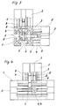
- Figur 3
- ein weiteres Ausführungsbeispiel der Erfindung in einer Querschnittsdarstellung des Tragstabes
- Figur 4
- das in der Figur 3 gezeigte Ausführungsbeispiel einer teilweise geschnittenen Vorderansicht.
- Im Innern des Profilstabes 2 und des Tragstabes 1 sind konzentrisch verteilt, vier Innenkammern 5 vorgesehen, die sich parallel zu den Längsnuten 3 erstrecken. Die gemeinsame Querachse zweier dieser Innenkammern 5 verläuft deckungsgleich mit der Längsachse des Tragstabes 1, so daß ihre öffnungen mittengenau auf der zugeordneten Längsnut des Tragstabes 1 liegen.
In Verlängerung der Längsachsen der Innenkammern 5 des Profilstabes 2 sind im Tragstab 1 Bohrungen 7 vorgesehen, durch die die Schrauben geführt sind.
Diese Bohrungen 7 sind abgesetzt, das heißt, ihre dem Profilstab 2 abgewandte Einführöffnung ist in ihrem Durchmesser größer als die gegenüberliegende Austrittsöffnung, wobei der Durchmesser der Einführöffnung geringfügig größer ist als der Schaftdurchmesser der Schraube 4. Dadurch kann sich der Schraubenkopf 6 im Innern des Tragstabes abstützen. Zweckmäßigerweise ist der Absatz in der Bohrung 7 in dem dem Profilstab zugewandten Bereich vorgesehen.
Mit geeigneten Hilfsmitteln, wie Bohrschablonen o.dgl. ist ein exaktes Bohren der Bohrungen 7 dann möglich, wenn der Profilstab 2 positionionsgenau am Tragstab anliegt. Weiter ist durch Einsatz von zwei außermittig angreifenden Schrauben 4 eine erhebliche verbesserte Belastungsfähigkeit, insbesondere hinsichtlich der Aufnahme von Torsionskräften gegeben.
Bei dem in den Figuren 3 und 4 dargestellten Ausführungsbeispiel sind an zwei benachbarten Längsseiten des Tragstabes 1, also rechtwinkelig zueinander, Profilstäbe 2 angebracht. Dabei liegen diese in einer gemeinsamen Querschnittsebene des Tragstabes 1.
Um auch bei dieser Konstuktion eine Verdrehsicherung zu erreichen, ist pro Profilstab 2 lediglich eine sich im Tragstab 1 abstützende Schraube 4 vorgesehen, während eine andere, in die entsprechende Innenkammer 5 des Profilstabes 2 eingeschraubte Schraube 8, sich an der Stirnseite des Profilstabes 2 abstützt und dabei mit ihrem zylindrischen Kopf 6 in die zugeordnete Längsnut 3 des Tragstabes 1 ragt. Sinnvollerweise ist der Schraubenkopf 6 dieser Schraube 8 in seinem Durchmesser etwa so groß wie die Breite der Längsnut 3.
Die jeweils zu der sich im Tragstab 1 abstützenden Schraube 4 fluchtende, in den anderen Profilstab 2 eingeschraubte Schraube 8, ist diejenige, die sich an der Stirnseite des Profilstabes abstützt, so daß ohne Probleme die Schraube 4 eingeschraubt werden kann, die jeweils den Profilstab 2 mit dem Tragstab verbindet.
Der Tragstab 1 und der Profilstab 2 sind im Querschnitt gleich gestaltet, wobei ihre Querschnittsfläche quadratisch ist und die Längsseiten mit jeweils einer mittig verlaufenden sich in Längsrichtung erstreckenden hinterschnittenen Längsnut 3 versehen sind.
Claims (6)
- Durch Schrauben mit einem Profilstab verbundener Tragstab, an dessen einer Längsseite der Profilstab mit einer Stirnseite anliegt, wobei der Tragstab auf seinen Längsseiten mit mittig verlaufenden Längsnuten versehen ist und wobei die Schraube quer durch den Tragstab geführt ist, sich in diesem mit ihrem Kopf abstützt und in eine sich in Längsachsrichtung erstreckende Innenkammer des Profilstabes eingeschraubt ist, dadurch gekennzeichnet, daß im Profilstab (2) zwei parallel und mit Abstand zueinander verlaufende Innenkammern (5) vorgesehen sind, deren gemeinsame Querachse deckungsgleich mit der Längsachse des Tragstabes (1) verläuft, und daß in jede Innenkammer (5) eine Schraube (4,8) eingedreht ist, von denen mindestens eine durch den Tragstab geführt ist.
- Tragstab nach Anspruch 1, dadurch gekennzeichnet, daß jede der in die Innenkammern (5) eingedrehten Schrauben (4) durch den Tragstab (1) geführt ist.
- Tragstab nach Anspruch 1 bei dem an zwei benachbarten Längsseiten jeweils ein Profilstab angeschlossen ist, dadurch gekennzeichnet, daß jeder Profilstab (2) mit einer Schraube (4) am Tragstab (1) festgelegt ist, während die andere Schraube (8) mit ihrem zylindrischen Kopf (6) in die zugeordnete Längsnut (3) des Tragstabes ragt.
- Tragstab nach Anspruch 1 oder 3, dadurch gekennzeichnet, daß der Kopfdurchmesser der Schrauben (4,8) etwa der Breite der Längsnut (3) entspricht.
- Tragstab nach Anspruch 3, dadurch gekennzeichnet, daß die mit ihrem Kopf in die Längsnut (3) ragende Schraube (8) mit der sich im Tragstab (1) abstützenden, in den anderen Profilstab (2) eingedrehten Schraube (4) fluchtet.
- Tragstab nach Anspruch 1, dadurch gekennzeichnet, daß die durch den Tragstab geführte Bohrung (7) abgesetzt ist, wobei der Absatz in dem dem Profilstab (2) zugewandten Bereich vorgesehen ist.
Applications Claiming Priority (2)
| Application Number | Priority Date | Filing Date | Title |
|---|---|---|---|
| DE9100099U DE9100099U1 (de) | 1991-01-07 | 1991-01-07 | |
| DE9100099U | 1991-01-07 |
Publications (2)
| Publication Number | Publication Date |
|---|---|
| EP0496107A1 true EP0496107A1 (de) | 1992-07-29 |
| EP0496107B1 EP0496107B1 (de) | 1994-05-18 |
Family
ID=6863122
Family Applications (1)
| Application Number | Title | Priority Date | Filing Date |
|---|---|---|---|
| EP91122161A Expired - Lifetime EP0496107B1 (de) | 1991-01-07 | 1991-12-23 | Durch Schrauben mit einem Profilstab verbundener Tragstab |
Country Status (6)
| Country | Link |
|---|---|
| US (1) | US5265972A (de) |
| EP (1) | EP0496107B1 (de) |
| AT (1) | ATE105920T1 (de) |
| DE (2) | DE9100099U1 (de) |
| DK (1) | DK0496107T3 (de) |
| ES (1) | ES2053266T3 (de) |
Cited By (3)
| Publication number | Priority date | Publication date | Assignee | Title |
|---|---|---|---|---|
| EP0616134A2 (de) * | 1993-03-19 | 1994-09-21 | Festo KG | Verbindungseinrichtung für Profilteile |
| DE19614084A1 (de) * | 1995-10-24 | 1997-04-30 | Helmut Kahl | Vorrichtung zum Verbinden von mit hinterschnittenen Längsnuten versehenen Profilstäben |
| DE102013005212A1 (de) | 2013-03-27 | 2014-10-16 | Vitalis Jung | Einrichtung zum Verbinden von mindestens zwei Bauteilen |
Families Citing this family (23)
| Publication number | Priority date | Publication date | Assignee | Title |
|---|---|---|---|---|
| DE9100099U1 (de) * | 1991-01-07 | 1991-06-13 | Bahr, Frank, 4952 Porta Westfalica, De | |
| US5439310A (en) * | 1993-05-25 | 1995-08-08 | The United States Of America As Represented By United States National Aeronautics And Space Administration | Connector systems for structures |
| US5799543A (en) * | 1993-09-02 | 1998-09-01 | Smc Kabushiki Kaisha | Actuator structural body |
| US5516225A (en) * | 1994-05-04 | 1996-05-14 | Kvols; Kevin | Corner connector and molding therefor |
| KR960011309B1 (ko) * | 1994-06-14 | 1996-08-22 | 이연희 | 조립식 책상의 조임장치 |
| JPH08159119A (ja) * | 1994-12-07 | 1996-06-18 | N I Shi Auto Tec Kk | 連結材 |
| US5657597A (en) | 1995-04-11 | 1997-08-19 | Environmental Building Technology, Ltd. | Building construction method |
| US5647650A (en) * | 1995-04-21 | 1997-07-15 | Metro Industries, Inc. | Modular storage and support assembly |
| DE19708198C2 (de) * | 1997-02-28 | 1999-02-04 | Thyssen Polymer Gmbh | Profilverbindung |
| KR200184811Y1 (ko) | 1997-09-18 | 2000-06-01 | 이연희 | 모서리지주의 연결조립장치 |
| DE19751167C1 (de) * | 1997-11-19 | 1999-06-24 | Bosch Gmbh Robert | Profilstab |
| DE10016608B4 (de) * | 2000-04-04 | 2013-02-07 | Helmuth Kahl | Spannglied zum stirnseitigen Verbinden von Profilstäben |
| US6742311B2 (en) * | 2002-09-17 | 2004-06-01 | Expo Design International | Modular transportable floor decking system |
| US8100600B2 (en) * | 2008-10-23 | 2012-01-24 | Robert Bosch Gmbh | Pivoting connector assembly for connecting two members |
| US20110225778A1 (en) * | 2010-03-18 | 2011-09-22 | Newfrey Llc | Interior trim sealing fastener |
| US9185974B2 (en) | 2010-06-02 | 2015-11-17 | Steelcase Inc. | Frame type workstation configurations |
| BG66739B1 (bg) * | 2012-05-22 | 2018-09-28 | "Стоа" Оод | Строителен профил, строителен набор, строителен комплект и закрепваща система за вентилируеми фасади |
| US9578772B2 (en) * | 2014-09-05 | 2017-02-21 | Emerson Network Power, Energy Systems, North America, Inc. | Cabinet frame enclosures, frame members and corresponding methods |
| USD773553S1 (en) | 2015-02-18 | 2016-12-06 | Stewart-Macdonald Manufacturing Company | Stringed instrument work station |
| US10517392B2 (en) | 2016-05-13 | 2019-12-31 | Steelcase Inc. | Multi-tiered workstation assembly |
| US10039374B2 (en) | 2016-05-13 | 2018-08-07 | Steelcase Inc. | Multi-tiered workstation assembly |
| US10662650B2 (en) * | 2017-10-31 | 2020-05-26 | Vention Inc. | T-slot extrusion structure |
| IT201900000127A1 (it) * | 2019-01-07 | 2020-07-07 | Cerloj Ema | Profilo estruso |
Citations (4)
| Publication number | Priority date | Publication date | Assignee | Title |
|---|---|---|---|---|
| EP0010475A2 (de) * | 1978-10-05 | 1980-04-30 | Jean Stoltz | Satz von Profilen und Zusatzteilen zur Herstellung von Möbeln |
| DE8529284U1 (de) * | 1985-10-15 | 1986-04-17 | Hans Bertschinger KG, 7209 Aldingen | Montagetisch |
| DE9006344U1 (de) * | 1990-06-05 | 1990-09-06 | Bahr, Frank, 4952 Porta Westfalica, De | |
| DE9100099U1 (de) * | 1991-01-07 | 1991-06-13 | Bahr, Frank, 4952 Porta Westfalica, De |
Family Cites Families (7)
| Publication number | Priority date | Publication date | Assignee | Title |
|---|---|---|---|---|
| US2972495A (en) * | 1959-06-08 | 1961-02-21 | Yalen Abraham | Spring metal u-shaped anchor |
| US3349538A (en) * | 1965-09-07 | 1967-10-31 | Crossman A Virginia | Tubular structure |
| US3816011A (en) * | 1970-04-03 | 1974-06-11 | American Metal Climax Inc | Entrance structure |
| DE3328142A1 (de) * | 1983-08-04 | 1985-02-21 | Item Industrietechnik und Maschinenbau GmbH, 5650 Solingen | Konstruktion aus profilstaeben |
| DE3438773A1 (de) * | 1984-10-23 | 1986-04-24 | Item Industrietechnik und Maschinenbau GmbH, 5650 Solingen | Querverbindung von profilstaeben |
| US4775259A (en) * | 1986-11-04 | 1988-10-04 | Benada Aluminum Of Florida, Inc. | Connector arrangement |
| US4747248A (en) * | 1987-05-14 | 1988-05-31 | Philips Industries Inc. | Corner construction for extruded frame components |
-
1991
- 1991-01-07 DE DE9100099U patent/DE9100099U1/de not_active Expired - Lifetime
- 1991-12-23 EP EP91122161A patent/EP0496107B1/de not_active Expired - Lifetime
- 1991-12-23 DE DE59101676T patent/DE59101676D1/de not_active Expired - Lifetime
- 1991-12-23 ES ES91122161T patent/ES2053266T3/es not_active Expired - Lifetime
- 1991-12-23 AT AT91122161T patent/ATE105920T1/de not_active IP Right Cessation
- 1991-12-23 DK DK91122161.2T patent/DK0496107T3/da active
-
1992
- 1992-01-06 US US07/816,979 patent/US5265972A/en not_active Expired - Lifetime
Patent Citations (4)
| Publication number | Priority date | Publication date | Assignee | Title |
|---|---|---|---|---|
| EP0010475A2 (de) * | 1978-10-05 | 1980-04-30 | Jean Stoltz | Satz von Profilen und Zusatzteilen zur Herstellung von Möbeln |
| DE8529284U1 (de) * | 1985-10-15 | 1986-04-17 | Hans Bertschinger KG, 7209 Aldingen | Montagetisch |
| DE9006344U1 (de) * | 1990-06-05 | 1990-09-06 | Bahr, Frank, 4952 Porta Westfalica, De | |
| DE9100099U1 (de) * | 1991-01-07 | 1991-06-13 | Bahr, Frank, 4952 Porta Westfalica, De |
Cited By (5)
| Publication number | Priority date | Publication date | Assignee | Title |
|---|---|---|---|---|
| EP0616134A2 (de) * | 1993-03-19 | 1994-09-21 | Festo KG | Verbindungseinrichtung für Profilteile |
| EP0616134A3 (de) * | 1993-03-19 | 1996-08-14 | Festo Kg | Verbindungseinrichtung für Profilteile. |
| DE19614084A1 (de) * | 1995-10-24 | 1997-04-30 | Helmut Kahl | Vorrichtung zum Verbinden von mit hinterschnittenen Längsnuten versehenen Profilstäben |
| DE19614084C2 (de) * | 1995-10-24 | 1999-02-04 | Helmut Kahl | Vorrichtung zum Verbinden von mit hinterschnittenen Längsnuten versehenen Profilstäben |
| DE102013005212A1 (de) | 2013-03-27 | 2014-10-16 | Vitalis Jung | Einrichtung zum Verbinden von mindestens zwei Bauteilen |
Also Published As
| Publication number | Publication date |
|---|---|
| ES2053266T3 (es) | 1994-07-16 |
| US5265972A (en) | 1993-11-30 |
| ATE105920T1 (de) | 1994-06-15 |
| DE59101676D1 (de) | 1994-06-23 |
| DK0496107T3 (da) | 1994-07-18 |
| EP0496107B1 (de) | 1994-05-18 |
| DE9100099U1 (de) | 1991-06-13 |
Similar Documents
| Publication | Publication Date | Title |
|---|---|---|
| EP0496107B1 (de) | Durch Schrauben mit einem Profilstab verbundener Tragstab | |
| EP1956250B1 (de) | Schienenartiges Profil | |
| AT405757B (de) | Verbindungsstück für die lösbare verbindung zweier profilstäbe, vorzugsweise aus leichtmetall | |
| EP0458069A1 (de) | Querverbindung von Profilstäben | |
| DE112018007572T5 (de) | Befestigungsstruktur und Energieumwandlungsvorrichtung, welches die Befestigungsstruktur verwendet | |
| EP0478877A1 (de) | Vorrichtung zum lösbaren Verbinden zweier Profilstäbe | |
| EP1853827B1 (de) | Profilverbinder | |
| DE2246478C3 (de) | Knotenpunktverbindung von räumlichen Fachwerkskonstruktionen | |
| EP0406801B1 (de) | Befestigungselement | |
| EP0541918A1 (de) | Querverbindung von Profilstäben | |
| DE3438773A1 (de) | Querverbindung von profilstaeben | |
| DE60004112T2 (de) | Schliesseinrichtung für eine Tür, insbesondere für eine Glastür | |
| DE102018206849B4 (de) | Vorrichtung zur klemmenden Befestigung | |
| EP1710452B1 (de) | System | |
| EP0423474B1 (de) | Vorrichtung zum lösbaren Verbinden von zwei Profilstäben | |
| EP0205733B1 (de) | Schraubverbindung | |
| DE19614084C2 (de) | Vorrichtung zum Verbinden von mit hinterschnittenen Längsnuten versehenen Profilstäben | |
| DE3418845C2 (de) | ||
| EP0511237B1 (de) | Mittelverbinder für insbesondere metallische webeschäfte | |
| DE3139701A1 (de) | Schalter mit einem mit einer befestigungsvorrichtung versehenen gehaeuse | |
| DE19604665A1 (de) | Querverbinder für Profilstäbe | |
| DE19717119C1 (de) | Zapfenverbinder zur Stirnverbindung wenigstens eines an einer Verbindungsstelle stirnseitig endenden Holzbalkens mit einem durchlaufenden Holzbalken | |
| EP3848543A1 (de) | Bandlappen eines bandes zur scharniergelenkigen verbindung eines flügelprofils mit einem rahmenprofil und ein solches band | |
| EP3546767A1 (de) | Verbinder für profile eines baukastensystems und baukastensystem | |
| EP3828426A1 (de) | Verbindungselement für mehrkantrohre |
Legal Events
| Date | Code | Title | Description |
|---|---|---|---|
| PUAI | Public reference made under article 153(3) epc to a published international application that has entered the european phase |
Free format text: ORIGINAL CODE: 0009012 |
|
| AK | Designated contracting states |
Kind code of ref document: A1 Designated state(s): AT BE CH DE DK ES FR GB GR IT LI NL SE |
|
| 17P | Request for examination filed |
Effective date: 19930109 |
|
| RAP1 | Party data changed (applicant data changed or rights of an application transferred) |
Owner name: PHOENIX-MECANO HOLDING AG |
|
| RIN1 | Information on inventor provided before grant (corrected) |
Inventor name: BAHR, FRANK |
|
| 17Q | First examination report despatched |
Effective date: 19930927 |
|
| ITF | It: translation for a ep patent filed |
Owner name: STUDIO INGG. FISCHETTI & WEBER |
|
| GRAA | (expected) grant |
Free format text: ORIGINAL CODE: 0009210 |
|
| AK | Designated contracting states |
Kind code of ref document: B1 Designated state(s): AT BE CH DE DK ES FR GB GR IT LI NL SE |
|
| REF | Corresponds to: |
Ref document number: 105920 Country of ref document: AT Date of ref document: 19940615 Kind code of ref document: T |
|
| GBT | Gb: translation of ep patent filed (gb section 77(6)(a)/1977) |
Effective date: 19940518 |
|
| REF | Corresponds to: |
Ref document number: 59101676 Country of ref document: DE Date of ref document: 19940623 |
|
| ET | Fr: translation filed | ||
| REG | Reference to a national code |
Ref country code: ES Ref legal event code: FG2A Ref document number: 2053266 Country of ref document: ES Kind code of ref document: T3 |
|
| REG | Reference to a national code |
Ref country code: DK Ref legal event code: T3 |
|
| REG | Reference to a national code |
Ref country code: GR Ref legal event code: FG4A Free format text: 3012539 |
|
| EAL | Se: european patent in force in sweden |
Ref document number: 91122161.2 |
|
| PLBE | No opposition filed within time limit |
Free format text: ORIGINAL CODE: 0009261 |
|
| STAA | Information on the status of an ep patent application or granted ep patent |
Free format text: STATUS: NO OPPOSITION FILED WITHIN TIME LIMIT |
|
| 26N | No opposition filed | ||
| REG | Reference to a national code |
Ref country code: GB Ref legal event code: IF02 |
|
| REG | Reference to a national code |
Ref country code: CH Ref legal event code: PCAR Free format text: ISLER & PEDRAZZINI AG;POSTFACH 1772;8027 ZUERICH (CH) |
|
| PGFP | Annual fee paid to national office [announced via postgrant information from national office to epo] |
Ref country code: DK Payment date: 20101223 Year of fee payment: 20 Ref country code: AT Payment date: 20101220 Year of fee payment: 20 Ref country code: FR Payment date: 20110107 Year of fee payment: 20 |
|
| PGFP | Annual fee paid to national office [announced via postgrant information from national office to epo] |
Ref country code: CH Payment date: 20101223 Year of fee payment: 20 |
|
| PGFP | Annual fee paid to national office [announced via postgrant information from national office to epo] |
Ref country code: GR Payment date: 20101224 Year of fee payment: 20 Ref country code: GB Payment date: 20101221 Year of fee payment: 20 Ref country code: SE Payment date: 20101221 Year of fee payment: 20 |
|
| PGFP | Annual fee paid to national office [announced via postgrant information from national office to epo] |
Ref country code: NL Payment date: 20110208 Year of fee payment: 20 Ref country code: DE Payment date: 20101215 Year of fee payment: 20 Ref country code: IT Payment date: 20101229 Year of fee payment: 20 |
|
| PGFP | Annual fee paid to national office [announced via postgrant information from national office to epo] |
Ref country code: ES Payment date: 20101222 Year of fee payment: 20 Ref country code: BE Payment date: 20101223 Year of fee payment: 20 |
|
| REG | Reference to a national code |
Ref country code: DE Ref legal event code: R071 Ref document number: 59101676 Country of ref document: DE |
|
| REG | Reference to a national code |
Ref country code: DE Ref legal event code: R071 Ref document number: 59101676 Country of ref document: DE |
|
| REG | Reference to a national code |
Ref country code: CH Ref legal event code: PL |
|
| BE20 | Be: patent expired |
Owner name: *PHOENIX-MECANO HOLDING A.G. Effective date: 20111223 |
|
| REG | Reference to a national code |
Ref country code: NL Ref legal event code: V4 Effective date: 20111223 |
|
| REG | Reference to a national code |
Ref country code: GB Ref legal event code: PE20 Expiry date: 20111222 |
|
| REG | Reference to a national code |
Ref country code: DK Ref legal event code: EUP |
|
| PG25 | Lapsed in a contracting state [announced via postgrant information from national office to epo] |
Ref country code: NL Free format text: LAPSE BECAUSE OF EXPIRATION OF PROTECTION Effective date: 20111223 |
|
| REG | Reference to a national code |
Ref country code: SE Ref legal event code: EUG |
|
| PG25 | Lapsed in a contracting state [announced via postgrant information from national office to epo] |
Ref country code: GB Free format text: LAPSE BECAUSE OF EXPIRATION OF PROTECTION Effective date: 20111222 |
|
| REG | Reference to a national code |
Ref country code: GR Ref legal event code: MA Ref document number: 940401873 Country of ref document: GR Effective date: 20111224 |
|
| REG | Reference to a national code |
Ref country code: AT Ref legal event code: MK07 Ref document number: 105920 Country of ref document: AT Kind code of ref document: T Effective date: 20111223 |
|
| REG | Reference to a national code |
Ref country code: ES Ref legal event code: FD2A Effective date: 20120411 |
|
| PG25 | Lapsed in a contracting state [announced via postgrant information from national office to epo] |
Ref country code: ES Free format text: LAPSE BECAUSE OF EXPIRATION OF PROTECTION Effective date: 20111224 |
|
| PG25 | Lapsed in a contracting state [announced via postgrant information from national office to epo] |
Ref country code: DE Free format text: LAPSE BECAUSE OF EXPIRATION OF PROTECTION Effective date: 20111224 |