EP0496003A1 - Détecteur de gaz à l'électrolyte solide et méthode pour mesurer la concentration du gaz à détecter dans un mélange de gaz - Google Patents
Détecteur de gaz à l'électrolyte solide et méthode pour mesurer la concentration du gaz à détecter dans un mélange de gaz Download PDFInfo
- Publication number
- EP0496003A1 EP0496003A1 EP90314239A EP90314239A EP0496003A1 EP 0496003 A1 EP0496003 A1 EP 0496003A1 EP 90314239 A EP90314239 A EP 90314239A EP 90314239 A EP90314239 A EP 90314239A EP 0496003 A1 EP0496003 A1 EP 0496003A1
- Authority
- EP
- European Patent Office
- Prior art keywords
- gas
- detected
- solid electrolytic
- electrolytic membrane
- screen
- Prior art date
- Legal status (The legal status is an assumption and is not a legal conclusion. Google has not performed a legal analysis and makes no representation as to the accuracy of the status listed.)
- Granted
Links
Images


Classifications
-
- G—PHYSICS
- G01—MEASURING; TESTING
- G01N—INVESTIGATING OR ANALYSING MATERIALS BY DETERMINING THEIR CHEMICAL OR PHYSICAL PROPERTIES
- G01N27/00—Investigating or analysing materials by the use of electric, electrochemical, or magnetic means
- G01N27/26—Investigating or analysing materials by the use of electric, electrochemical, or magnetic means by investigating electrochemical variables; by using electrolysis or electrophoresis
- G01N27/416—Systems
- G01N27/417—Systems using cells, i.e. more than one cell and probes with solid electrolytes
Definitions
- This invention relates to a solid electrolyte gas sensor and a method of measuring a concentration of a gas in a gas mixture. More specifically, it relates to a solid electrolyte gas sensor having such a structure that an electrode reaction rate of a gas to be detected (hereinafter sometimes referred to as a gas G) in a detection portion of the solid electrolyte gas sensor and a rate of discharging a generated molecular gas from said detection portion are greater than a rate of feeding the gas to said detection portion, and a method of measuring a concentration of a gas G in a gas mixture on the basis of the principle of said solid electrolyte gas sensor.
- a gas G an electrode reaction rate of a gas to be detected
- a solid electrolyte gas sensor of a limiting current type is conventionally known. It is known that the advantages of the solid electrolyte gas sensor of a limiting current type are that it can measure oxygen gas in a wider concentration range than an oxygen gas sensor of a concentration cell type, that it can be decreased in size, and that it requires no reference gas.
- the solid electrolyte gas sensor of a limiting current type has a basic structure in which an electrode of the detection portion thereof is covered with a cap having a capillary or a porous ceramic such that an electrode reaction rate of a gas G in the detection portion and a discharge rate of a generated molecular gas from said detection portion are controlled to be greater than a rate of feeding the gas G to said detection portion.
- a mixture gas which contains the gas to be detected reaches an electrode of the detection portion through the capillary or pores of the porous ceramic in the above structure. It is therefore made possible to control the rate of feeding the mixture gas to be measured and, consequently, the gas G to the detection portion by suitably changing the size of the capillary or the diameter of the pores.
- the detection portion generally has a structure in which there are disposed an ionically conductive solid electrolyte and two electrodes sandwiching said electrolyte.
- the gas G reaches one electrode (with which to generate ions derived from the gas G) of the above two to form ions under an electrode reaction.
- the ions formed reach the other electrode through the ionically conductive solid electrolyte.
- the ions are converted to a molecular gas under an electrode reaction which proceeds on this "other" electrode reversely to the above ionization reaction, and discharged from this electrode to a space surrounding this electrode.
- the solid electrolyte gas sensor of a limiting current type uses the above structure, in which the electrode of the detection portion is covered with a cap having a capillary or a porous ceramic, in order to control the rate of feeding a gas to the detection portion and, consequently, control a diffusion rate. Therefore, when the gas mixture containing a gas G, which passes through the capillary or the pores of the porous ceramic, contains contaminants, e.g. suspended solids or mist, such suspended solids and the like gradually adhere to the interior of the capillary or the pores and prevent the gas G from reaching the detection portion by diffusion.
- contaminants e.g. suspended solids or mist, such suspended solids and the like gradually adhere to the interior of the capillary or the pores and prevent the gas G from reaching the detection portion by diffusion.
- a solid electrolyte gas sensor of a limiting current type which has a structure in which a gas G contained in a mixture gas to be measured is fed to a detection portion of the sensor through a gas control screen structured such that a solid electrolytic membrane is sandwiched with two porous conductors.
- a solid electrolyte gas sensor for the measurement of a concentration of a gas to be detected in a gas mixture, the sensor comprising:
- ions derived from the gas G means the following two types of ions: ions formed by ionization of a gas itself to be detected such as oxygen ion (O2 ⁇ ) when the gas to be detected is an oxygen gas, and ions formed by an electrode reaction of a gas to be detected on the porous conductor such as hydrogen ion when the gas to be detected is carbon monoxide.
- ions formed by ionization of a gas itself to be detected such as oxygen ion (O2 ⁇ ) when the gas to be detected is an oxygen gas
- ions formed by an electrode reaction of a gas to be detected on the porous conductor such as hydrogen ion when the gas to be detected is carbon monoxide.
- the solid electrolyte gas sensor of this invention basically has (A) a screen with which to control a permeation rate of a gas G, and (B) a detection portion in which to detect an amount of the gas G which has permeated.
- the major characteristic structural feature of the solid electrolyte gas sensor of this invention is the above screen (A). Since the solid electrolyte gas sensor of this invention is provided with the screen (A), (C) the amount of ions which permeate the first solid electrolytic membrane of the above screen (A) per unit time is made smaller than the amount of ions which permeate the second solid electrolytic membrane of the above detection portion (B) per unit time under conditions that the sensor is in operation. In other words, the amount of ions derived from the gas G, which reach the detection portion (B), is controlled due to the presence of the screen (A).
- a conventional solid electrolyte gas sensor of a limiting current type has a structure in which a detection portion is formed of a solid electrolyte 1 and electrodes 3 and 4 which are disposed to sandwich the solid electrolyte 1, and a cap 2 having a capillary (in Fig. 4) or a porous ceramic 20 (in Fig. 3) is placed on one of the two electrodes so that an amount of a gas for a reaction is limited on said electrode.
- sensors of the above type have been developed to measure oxygen gas as a gas to be detected.
- such sensors can be applied to carbon dioxide gas and other various gases such as halogen gases, SO2, SO3, CO, NO, NO2, NH3, H2S, and the like.
- the sensor of this invention too, can be used to measure concentrations of a variety of gases.
- a voltage equivalent to or higher than a voltage required for reduction of oxygen is applied between two electrodes 3 and 4 with a power source 5 such that the electrode 3 provided with a cap or a porous ceramic constitutes a cathode and the other electrode 4 constitutes an anode.
- molecular oxygen (O2) is reduced to an oxygen ion (O2 ⁇ ), and the oxygen ion migrates to the anode side through an ion permeation layer 1 comprising a solid electrolyte.
- the oxygen ion is then oxidized on the anode to form an oxygen gas, which is then discharged.
- An electric current occurs due to this migration of oxygen ion. This current is measurable with an ampere meter 6 connected to the power source 5 in series via a lead wire 15.
- molecular oxygen fed to the cathode side is converted to an oxygen ion and drawn to the anode side. Therefore, when the amount of oxygen to be fed to the cathode is controlled by means of a diffusion resistance of a capillary of the cap 2 or pores of the porous ceramic 20, a limiting current occurs which has a constant relationship with an oxygen concentration in a gas mixture to be measured. This limiting current is measured with the above ampere meter 6.
- An oxygen concentration can be found on the basis of the measured limiting current and a calibration curve preliminarily prepared with regard to the relationship between an oxygen content and a limiting current value. In a standardized device, it is possible to allow such a device to directly display an oxygen concentration on the basis of a limiting current value by reference to the above calibration curve.
- this invention does not use a method of controlling the diffusion amount and diffusion rate of a gas G by means of a cap with a capillary or a porous ceramic, but employs a method of controlling the supply amount and supply rate of a gas G contained in a gas mixture to be measured by means of a gas control screen which will be detailed later.
- the gas to be detected in a gas mixture measured can reach the detection portion of the sensor without any migration through pores by diffusion. Therefore, there can be obtained a sensor which is almost free from problems in variability depending upon products, variability in measurement value due to clogging, etc. in use for a long period of time, and the like.
- the screen (A) to control the permeation rate of a gas to be detected comprises (a1) a first solid electrolytic membrane selectively permeable to an ion derived from a specific gas to be detected and (a2) a plurality of first porous conductors being present on both front and reverse surfaces of said first solid electrolytic membrane and electrically connected to each other so as to give a potential required for oxidation and reduction of said gas to be detected.
- the ion derived from a gas to be detected means an ion which the gas to be detected forms by an electrode reaction.
- the ion which the gas to be detected forms by an electrode reaction differs depending upon what kind of gas is to be detected.
- the electrode reaction which generates an ion derived from a gas to be detected takes place under a potential applied to a plurality of the first porous conductors electrically connected to each other.
- the first solid electrolytic membrane (a1) selectively permeable to an ion derived from a gas to be detected is different in material depending upon said ion. Materials therefor are known, and such materials are usable in this invention as well.
- a gas to be detected is oxygen
- usable as this material is a solid electrolyte prepared from a solid solution of at least one CaO, Y2O3, Gd2O3, Sm2O3, MgO, etc., in at least one of oxides such as CeO2, ZrO2, HfO2, ThO2, Bi2O3, etc.
- a CeO2-containing solid electrolyte is particularly preferred, since it exhibits high ionic conductivity at a low temperature and an oxygen sensor using it can be operated at a low temperature.
- the amount of the above dissolved solid differs depending upon a combination with the oxide which dissolves the solid. This amount is, however, in the range of 2 to 40 %.
- known proton-conductive solid electrolytes can be used without any limitation.
- proton-conductive electrolytes examples include antimonic acid (Sb2O5 ⁇ nH2O), zirconium phosphate (Zr(HPO4)2 ⁇ H2O), phosphorus molybdate (H3Mo12O40 ⁇ nH2O), phosphorus wolframate (H3W12O40 ⁇ nH2O), uranyl phosphate (HUO2PO4 ⁇ nH2O), inorganic ion exchangers of which the typical example is H-type zeolite, polystyrene sulfonate and organic polymer ion exchangers of which the typical example is Nafion (trade name, supplied by du Pont de Nemours & Co.).
- the above proton-conductive solid electrolytes may be used alone or in combination.
- the gas to be detected is a halogen gas
- known halogen ion-conductive solid electrolytes can be used without any limitation.
- fluorine gas ⁇ -PbF2, CaF2, SrF2, LaF2 and TlSn2F3 can be used alone or in combination.
- KAg4I5, PbCl2, PbBr, etc. may be used.
- the gas to be detected is SO2, SO3, CO, CO2, NO2, or the like, K2SO4, K2CO3, Ba(NO3)2, etc., can be used.
- the ion permeation layer formed of a solid electrolyte and used in the gas G control screen is basically required to have such a constitution that, in the detection portion, it feeds a gas (to be detected) at a lower rate than a rate of discharging the gas detected.
- the solid electrolyte for use in said screen layer may be (i) a solid electrolyte having a smaller transport number than a solid electrolyte used in the detection portion, (ii) a solid electrolyte which is the same as that used in the detection position but whose effective area is decreased (e.g. to about 10 to 90 %), or (iii) a solid electrolyte which is the same as that used in the detection position but whose thickness is increased.
- the transport number can be decreased by decreasing the ion exchange capacity of the solid electrolyte, by incorporating a metal powder having high electrical conductivity, or by some other method.
- the ion permeation layer constitutes a gas barrier and has a practical function of enduring industrial use. Therefore, the ion permeation layer has a thickness of 0.1 to 5,000 ⁇ m.
- the ion permeation layer is made from an inorganic material, its thickness is preferably 0.5 to 1,000 ⁇ m, and when it is an organic material, its thickness is preferably 1 to 2,000 ⁇ m.
- the ion permeation layer is produced, e.g. by a method of molding a fine powder of the above solid electrolyte, a method of molding it and sintering the molded product, a sputtering method, an ion plating method, an evaporation method, or the like.
- a commercially available material such as Nafion may be used as such.
- Examples of the material for the porous conductors which are present on both surfaces of the ion permeation layer comprising the solid electrolyte are preferably noble metals such as platinum, palladium, rhodium, silver, etc., and oxides of these, oxides consisting of a perovskite oxides having a general formula of La 1-x Sr x BO3 (in which B is an element such as Co, Cu, Fe, Ni, etc., and x is a numeral of 0.01 to 0.5), and composite compositions prepared by mixing the above noble metals with metal oxides.
- the porous conductors have a thickness of 0.1 to 50 ⁇ m, preferably 0.2 to 30 ⁇ m. A molecular gas or a formed ion can be efficiently diffused into the ion permeation layer since the conductors are porous.
- the porous conductors can be formed on the solid electrolytic membrane by a known method, e.g. a screen printing, vacuum evaporation, chemical plating, ion plating or sputtering method.
- a known method e.g. a screen printing, vacuum evaporation, chemical plating, ion plating or sputtering method.
- the gas sensor can be heated as required.
- the gas sensor may be heated by heat radiation from an external heat source or by thermal conduction or heat radiation from a heater provided to the gas sensor.
- the place where the heater is provided is not speicially limited as far as the heater does not prevent operation of the gas sensor.
- the detection portion (B) for detecting a permeation amount of ions of a gas to be detected comprises (b1) a second solid electrolytic membrane selectively permeable to an ion derived from a specific gas to be detected, (b2) a plurality of porous conductors being present on both front and reverse surfaces of the second solid electrolytic membrane and electrically connected with each other so as to give a potential required for oxidation and reduction of said gas G to be detected, and (b3) means of electrically measuring an amount of an ion derived from the gas G which permeates the second solid electrolytic membrane.
- first solid electrolytic membrane (a1) and the first porous conductors (a2) in the screen (A) apply directly to the second solid electrolytic membrane (b1) and the second porous conductors (b2) in the detection portion (B).
- Figs. 1 and 2 show basic structures of the gas sensor of this invention.
- the gas sensor of this invention has a detection portion comprising electrodes 10 and 11 and an ion permeation layer 9 formed of a solid electrolyte and placed between the electrodes 10 and 11, and a gas G control screen comprising porous conductors 12 and 18 and an ion permeation layer 8 formed of a solid electrolyte and placed between the porous conductors 12 and 18.
- the porous conductors 12 and 18 are electrically connected with each other.
- the detection portion of the sensor has the same mechanism as that of a conventional solid electrolyte gas sensor of a limiting current type. That is, the detection portion comprises porous electrodes 10 and 11 and an ion permeation layer 9 placed between the porous electrodes 10 and 11, and these two electrodes 10 and 11 are connected with each other through a power source 5 and an ampere meter 6 in series via a lead wire 15 to form a circuit.
- the gas G control screen and the detection portion are gastightly sealed with a sealing member 7 in their peripheries.
- the material for the sealing member 7 is not specially limited if it is impermeable to a gas to be detected, e.g. oxygen.
- glass As a sealing member, glass, inorganic cement, a ceramic having a low melting point, etc., are usable. Of these materials, it is preferred to use those which have a thermal expansion coefficient equivalent to or slightly lower than that of the ion permeation layer. Further, in view of junction, it is preferred to use those which are fine particles having a diameter of not more than 10 ⁇ m, preferably not more than 5 ⁇ m. Furthermore, it is industrially advantageous to form a casing 14 by coating outer side surfaces of the gas control screen and the detection portion with a sealing material in order to improve gastightness and protect the outer surfaces.
- This invention has its characteristic features in use of two ion permeation layers 8 and 9 which are formed of a solid electrolyte, and known solid electrolytes can be used, as described above, if they are permeable to intended ions.
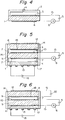
- Fig. 5 shows a specific embodiment of the gas sensor of this invention, in which porous conductors 12 and 18 of a gas G control screen are connected at one end, and an electromotive force in said screen portion is produced by a difference between a concentration of a gas G in contact with the conductor 12 and a concentration of a gas G in contact with the conductor 18.
- Said screen and a detection portion are sealed in their peripheries with a sealing member 7 to form a space b.
- the detection portion of the sensor is provided with a space c in its lower portion, and further provided with an electrically insulating porous element 17, a heater 13 and a power source 16 for said heater.
- the electrically insulating porous element 17 has pores whose diameter and number are sufficient to discharge a gas, drawn into the space c, without any resistance.
- Fig. 6 shows another embodiment, in which a voltage equivalent to or higher than a voltage required to produce an electrode reaction of a gas G contained in a gas mixture measured on a surface of a conductor 12 is charged between the conductor 12 and a conductor 18 in a gas G control screen with an external power source 22. Further, this embodiment has a constitution in which a porous element 17 and an electrode 11 are brought into intimate contact for heating efficiency.
- Fig. 7 shows another embodiment in which a spacer 19 formed of a porous substance is placed in a space b existent between a gas G control screen and a detection portion.
- the material for the spacer is not specially limited as far as it does not limit permeation of a gas to be detected.
- porous ceramics such as SiO2 ⁇ MgO, SiO2 ⁇ Al2O3, zeolite and SiO2. These porous ceramics may be freely selected as far as they does not limit permeation of a gas to be detected.
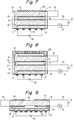
- Fig. 8 shows an embodiment in which a cover 23 formed of a wire net, a ceramic having a high opening ratio or other porous substance is provided in order to protect a conductor 12 which is to be in contact with a gas mixture to be measured.
- Fig. 9 shows another embodiment in which a gas G control screen covers a detection portion, and a solid electrolytic membrane 8 of the gas G control screen and a solid electrolytic membrane 9 of a detection portion are formed as a unitary structure.
- a gas fed through said screen is retained in a space b formed with a cover 21, and then fed to the detection portion. That is, an ion formed by an electrode reaction on a conductor 12 of the gas G control screen is converted to a molecular gas with a conductor 18 and fed to the space b.
- This molecular gas in the space b is then drawn in the detection portion, and discharged through an electrode 11.
- This embodiment has characteristic features in that due to a heater 13 positioned on a lower surface, the gas G control screen and the detection portion of the sensor can be uniformly heated.
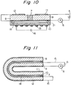
- Fig. 10 shows a variant of the embodiment shown in Fig. 9.
- a solid electrolytic membrane 8 and a solid electrolytic membrane 9 are isolated with an insulating sealing member 7, and a conductor 18 of a gas G control screen and an electrode 10 of a detection portion are integrally constituted.
- the conductor 18 and the electrode 10 have the same potential.
- the measurement is possible without any problem by retaining a potential difference between a conductor 12 and the conductor 18 and a potential difference between the electrode 10 and an electrode 11 in a range required for an electrode reaction of a gas formed from the ion which is derived from the gas G.
- Fig. 11 shows a variant which is basically the same as the embodiment shown in Fig. 1.
- the structure of the sensor of this invention shall not be limited to a plate-form, and for example, it can be cylindrical as shown in Fig. 11.
- this invention shall not be limited to the above embodiments, but includes any embodiment which is a solid electrolyte gas sensor of a limiting current type and employs a process in which a gas to be fed to the detection portion permeates the ion permeation layer formed of the solid electrolytic membrane as an ion and then fed again.
- a method of measuring a concentration of a gas to be detected in a gas mixture which comprises:
- a gas sensor was placed in a gas mixture containing a different concentration of a gas to be detected, and a D.C. voltage was applied to electrodes of a detection portion.
- the applied voltage was continuously changed at a rate of 0.04 V/min., and currents occurred were measured with an ampere meter and recorded in a recorder.
- voltages at which a limiting current was commonly obtained in the concentration of a gas to be detected were regarded an optimum applied voltage.
- an oxygen sensor was constituted of an oxygen detection portion in which electrodes (of a porous conductor) 10 and 11 were formed on both the surfaces of an ion-permeable layer (solid electrolytic membrane) 9, an oxygen control screen in which porous conductors 12 and 18 formed on both surfaces of an ion-permeable layer (solid electrolytic membrane) 8 were electrically connected to each other, and a heater portion in which a heater 13 was formed on a porous ceramic 17.
- the oxygen detection portion, the oxygen control screen and the heater portion were bonded with a glass 7, and externally sealed with a glass 14.
- a direct current voltage 16 was applied to the heater 13 of the heater portion to heat an oxygen sensor element to 450 ° C.
- a direct current voltage 5 was applied so that in the oxygen detection portion the electrode 10 on the side of the oxygen control screen constituted a cathode and the electrode 11 on the heater portion side constituted an anode. Further, an ampere meter 6 was connected to a power source in series to measure an occurring current.
- the ion-permeable layers 8 and 9 there were used dense disk-formed solid electrolyte sintered members having a diameter of 4 mm and a thickness of about 0.3 mm, which were prepared by molding a (CeO2) 0.7 (CaO) 0.3 powder of a solid solution of 30 mol% of calcium oxide in oxygen ion-conducting cerium oxide and sintering the resultant molded material.
- the electrodes 10 and 11 were those which were prepared by screen-printing a platinum paste and baking the resultant printed plates at 800 ° C. And a platinum wire was used as a lead wire 15. Further, the porous conductors 12 and 18 of the oxygen control screen were those which were prepared by screen-printing a platinum paste on both surfaces of the ion-permeable layer 8, partly connecting the resultant printed layers along an end surface of the ion-permeable layer 8 with a platinum paste, and baking the resultant plate at 800 ° C.
- the porous ceramic 17 used in the heater portion was a disk-formed sintered material having a diameter of 4 mm and a thickness of about 0.6 mm, which was a heat-resistant inorganic material having sufficient pores to prevent oxygen diffusion from rate-controlling and a thermal expansion coefficient nearly equivalent to that of the ion-permeable layer, and which was prepared by molding an MgO ⁇ SiO2 powder into a disk and sintering it.
- known materials are suitably usable.
- the heater 13 used in this Example is that which was prepared by screen-printing a platinum paste on the above porous ceramic to form a corrugated layer and baking it at 900 ° C.
- the bonding glass 7 preferably usable are those having a thermal expansion coefficient equivalent to or slightly smaller than that of the ion-permeable layer and a particle diameter of not more than 10 ⁇ m, preferably not more than 5 ⁇ .
- a glass powder having an average diameter of 6 ⁇ m was milled with a ball mill for 3 hours, and the milled glass powder was formed into a paste by adding terepineol and ethyl cellulose. Then, the oxygen detection portion, the heater portion and the oxygen control screen were bonded by screen-printing the paste on those portions of the ion-permeable layer 9 on which the electrodes were not formed.
- the glass 14 used for the sealing was formed by applying the same glass paste as above to the outer surface of the oxygen sensor element twice. These glass members 7 and 14 were densified by sintering them at 620 ° C so that oxygen did not permeate therethrough.
- (2) The above sensor was placed in a gas mixture to be measured which contains a different oxygen concentration, and a current was measured by changing voltages to be applied between the electrodes 10 and 11.
- Fig. 12 shows the results, in which the ordinate axis indicates currents ( ⁇ A) and the abscissa axis indicates voltages (V). In Fig. 12, with regard to all of oxygen concentrations, there are observed portions showing no change in current while the voltage was changed, i.e.
- Fig. 12 shows that 800 mV is a voltage with which the limiting current values are obtained commonly with regard to all of the oxygen contents.
- Table 1 shows the relationship between the limiting current value and the oxygen concentration at the 800 mV.
- Table 1 Oxygen concentration 5 10 21 30 50 70 80 90 Limiting current ( ⁇ A) 8.3 9.5 13.4 17.5 29.2 45.8 58.5 79.3
- the relationship shown in Table 1 is illustrated in Fig 13, in which the ordinate axis indicates limiting current values ( ⁇ A), the abscissa axis on the bottom indicates a function of oxygen concentration -ln(1-PO2/P) in which P is a total pressure of a gas measured and PO2 is an oxygen partial pressure, and the abscissa axis on the top indicates oxygen concentrations (%).
- Fig. 13 is used as a calibration curve to determine an oxygen concentration in a gas mixture of which the oxygen concentration is unknown. That is, a gas mixture is measured with an oxygen sensor shown in Fig.
- the oxygen concentration in the gas mixture is determined on the basis of the limiting current value by reference to the above calibration curve.
- thirty oxygen sensors were prepared in the same way as in the preparation of the above oxygen sensor, and a degree of variability of outputted current among these oxygen sensors were determined. That is, an optimum voltage obtained by measurement of limiting current characteristics was applied to each of the oxygen sensors, and output currents in atmosphere were measured.
- Table 2 shows a maximum value, average value and variability coefficient of outputted currents. Table 2 shows that the oxygen sensor of this invention exhibits a smaller variability in outputted current than a conventional oxygen sensor having pores or a porous ceramic, and can be produced with good reproductiveness.
- An oxygen sensor element as shown in Fig. 11 was produced.
- This sensor was produced by preparing an oxygen control screen, which was formed of a cylindrical ion permeable layer 8 and porous conductor layers 12 and 18 formed on surfaces of the ion permeable layer 8, and bonding an oxygen sensor portion, which was formed of an ion permeation layer 9 having the same form as, and being smaller than, the ion permeable layer 8 and an electrode 11 formed on surfaces of the ion permeable layer 9, to the oxygen control screen with a glass 7 such that the oxygen sensor portion was positioned within the oxygen control screen.
- the oxygen control screen was positioned outside and the oxygen sensor portion was positioned inside.
- Table 3 shows that the oxygen sensor of this Example 6 is almost free from a decrease in output current caused by the clogging differently from a conventional oxygen sensor having pores or a porous ceramic, and that the oxygen sensor of this invention exhibits a stable output for a long period of time.
- Table 2 Current ( ⁇ A) Variation coefficient Average Minimum Maximum Example 1 13.8 12.4 15.1 5.4
- Example 2 14.6 11.7 16.0 6.1
- Example 3 23.4 20.1 25.7 5.7
- Example 4 30.5 25.4 36.1 5.8
- Example 5 25.3 20.6 32.6 6.0
- Example 6 56.2 43.8 68.3 6.3
- Sensor with pores 220 138 293 24.8 Sensor with porous ceramic 128 45 240 43.6
- An oxygen sensor element having a structure as shown in Fig. 5 was produced in the same way as in Example 1 except for the following: A sintered body of a solid solution of 7 mol% of yttrium oxide in oxygen ion-conducting zirconium oxide (ZrO2) 0.93 (Y2O3) 0.07 was used as ion permeable layers 8 and 9. Platinum was used as porous electrodes 10 and 11 and porous conductor layers 12 and 18. The same heater and the same glass as those in Example 1 were used as a heater 13 and glass members 7 and 14. A direct current voltage was applied to the heater 13 to heat the element to 500 ° C.
- An oxygen sensor element having a structure as shown in Fig. 5 was produced in the same way as in Example 1 except for the following: A composite material of La 0.6 Sr 0.4 CoO3, which was perovskite-type oxide, with platinum was used as porous electrodes 10 and 11 and porous conductor layers 12 and 18, a sintered material of (CeO2) 0.7 (CaO) 0.3 was used as ion permeable layers 8 and 9, and the same heater and the same glass as those in Example 1 were used as a heater 13 and glass members 7 and 14.
- the composite material used for the electrodes 10 and 11 and the conductor layers 12 and 18 was a paste prepared by mixing lanthanum carbonate, strontium carbonate and cobalt acetate in a predetermined ratio, firing the resultant mixture, milling the resultant fired product to form a powder of perovskite-type oxide La 0.6 Sr 0.4 CoO3, and mixing this powder with a platinum paste at a weight ratio of 2:8, and the electrodes 10 and 11 and the conductor layers 12 and 18 were formed by screen-printing the above paste.
- a direct current voltage was applied to the heater 13 to heat the element to 400 ° C.
- a hydrogen sensor having a structure shown in Fig. 1 was produced.
- a mixture of proton-conducting antimonic acid (Sb2O5 ⁇ H2O) with a Teflon powder was used as ion permeable layers 8 and 9.
- Porous electrodes 10 and 11 and porous conductor layers 12 and 18 were formed by molding platinum black concurrently with molding the proton conductor into disks having a diameter of 5 mm.
- the ion permeable layers 8 and 9 formed in such a manner that the ion permeable layer 8 had a greater thickness than the ion permeable layer 9 in order to differentiate an ion permeation amount per unit time.
- a detection portion and an ion permeable layer were bonded with a glass 7 and the end portion thereof was sealed with a glass 14 in the same way as in Example 1.
- the glass members 7 and 14 were so densified as to prevent gas permeation by sintering them at 250 ° C.
- the above sensor had sensitivity not only to hydrogen but also to combustible gases such as carbon monoxide, ethanol, etc.
- a fluorine gas sensor having a structure as shown in Fig. 6 was produced.
- Ion permeable layers 8 and 9 were formed by doping fluorine ion conducting CaF2 with NaF, molding the doped material into disks having a diameter of 5 mm and thickness of 0.4 mm and sintering the disks.
- the ion permeable layer 8 was required to show a smaller ion permeation amount per unit time than the ion permeable layer 9. Therefore, the transport numbers thereof were changed by changing the NaF amount for the doping as follows.
- the ion permeable layer 8 had been formed by doping the ion conducting CaF2 with 0.5 % of NaF, and the ion permeable layer 9 had been formed by doping CaF2 with 1 % of NaF.
- Porous electrodes 10 and 11 and porous conductor layers 12 and 18 were formed by screen-printing platinum and baking the printed material at 800 ° C.
- a detection portion and an ion permeable layer were bonded with a glass 7, and the end portion thereof was sealed with a glass 14. These glass members were so densified by sintering them at 620 ° C as to prevent gas permeation.
- a direct current voltage 16 was applied to a heater 13 to heat the sensor element to 450 ° C. And in order to promote ionization on the conductor layer 12, 1 V of a direct voltage 22 was applied between the conductor layers 12 and 18 which were formed on surfaces of a gas G control screen.
- a direct current voltage 5 was applied such that the electrode 10 constituted an anode and the electrode 11 constituted a cathode, and limiting current characteristics were measured in the same way as in Example 1 to give limiting current values having a constant relationship with a fluorine gas concentration in a gas measured.
- Table 7 shows the relationship between the fluorine gas concentration and the limiting current value.
- Table 7 Fluorine concentration (ppm) 500 1,000 5,000 8,000 Limiting current ( ⁇ A) 4.2 7.5 43.2 70.5
- the gas sensor of this invention electrochemically limits inflow of a gas with the ion permeable layer instead of using pores or a porous ceramic to limit gas diffusion, variability in characteristics depending upon production conditions is small, and no degradation in characteristics due to clogging of pores, etc., is observed.
- the gas sensor of this invention makes it possible to accurately measure a gas concentration in a wide range for a long period of time.
Priority Applications (4)
| Application Number | Priority Date | Filing Date | Title |
|---|---|---|---|
| JP1268029A JPH03130657A (ja) | 1989-10-17 | 1989-10-17 | 酸素センサ |
| DE69030098T DE69030098T2 (de) | 1989-10-17 | 1990-12-24 | Gassensor mit festem Elektrolyt und Verfahren zum Messen der Konzentration des zu detektierenden Gases in einer Gasmischung |
| EP90314239A EP0496003B1 (fr) | 1989-10-17 | 1990-12-24 | Détecteur de gaz à l'électrolyte solide et méthode pour mesurer la concentration du gaz à détecter dans un mélange de gaz |
| US07/634,738 US5124021A (en) | 1989-10-17 | 1990-12-27 | Solid electrolyte gas sensor and method of measuring concentration of gas to be detected in gas mixture |
Applications Claiming Priority (2)
| Application Number | Priority Date | Filing Date | Title |
|---|---|---|---|
| JP1268029A JPH03130657A (ja) | 1989-10-17 | 1989-10-17 | 酸素センサ |
| EP90314239A EP0496003B1 (fr) | 1989-10-17 | 1990-12-24 | Détecteur de gaz à l'électrolyte solide et méthode pour mesurer la concentration du gaz à détecter dans un mélange de gaz |
Publications (2)
| Publication Number | Publication Date |
|---|---|
| EP0496003A1 true EP0496003A1 (fr) | 1992-07-29 |
| EP0496003B1 EP0496003B1 (fr) | 1997-03-05 |
Family
ID=40184979
Family Applications (1)
| Application Number | Title | Priority Date | Filing Date |
|---|---|---|---|
| EP90314239A Expired - Lifetime EP0496003B1 (fr) | 1989-10-17 | 1990-12-24 | Détecteur de gaz à l'électrolyte solide et méthode pour mesurer la concentration du gaz à détecter dans un mélange de gaz |
Country Status (4)
| Country | Link |
|---|---|
| US (1) | US5124021A (fr) |
| EP (1) | EP0496003B1 (fr) |
| JP (1) | JPH03130657A (fr) |
| DE (1) | DE69030098T2 (fr) |
Cited By (4)
| Publication number | Priority date | Publication date | Assignee | Title |
|---|---|---|---|---|
| WO1997013147A1 (fr) * | 1995-09-29 | 1997-04-10 | Matsushita Electric Industrial Co., Ltd. | Detecteur de gaz et son procede de fabrication |
| EP0810433A2 (fr) * | 1996-05-30 | 1997-12-03 | Ngk Insulators, Ltd. | Analyseur de gaz et procédé d'étalonnage dudit analyseur |
| EP0994346A2 (fr) * | 1998-10-09 | 2000-04-19 | Basf Aktiengesellschaft | Sonde pour la détection des concentrations actuelles de plusieurs composants gazeux dans un gaz |
| WO2009062813A1 (fr) * | 2007-11-14 | 2009-05-22 | Robert Bosch Gmbh | Capteur de gaz à potentiel de référence variant dans le temps |
Families Citing this family (24)
| Publication number | Priority date | Publication date | Assignee | Title |
|---|---|---|---|---|
| US5360528A (en) * | 1992-07-20 | 1994-11-01 | General Motors Corporation | Wide range oxygen sensor |
| JP3314426B2 (ja) * | 1992-12-25 | 2002-08-12 | 株式会社デンソー | 酸素センサ |
| US5413691A (en) * | 1992-12-25 | 1995-05-09 | Tokyuama Corporation | Solid electrolyte gas-sensing device |
| US5409591A (en) * | 1993-09-24 | 1995-04-25 | Baker; Charles K. | Selective electrochemical detector for nitric oxide and method |
| US5857250A (en) * | 1994-10-25 | 1999-01-12 | Texas Instruments Incorporated | Method of forming a capacitance type gaseous sensing device and apparatus thereof |
| JPH09127051A (ja) * | 1995-11-02 | 1997-05-16 | Mitsubishi Heavy Ind Ltd | 固体電解質型酸素ポンプ |
| KR100345233B1 (ko) * | 1999-11-08 | 2002-07-25 | 한국전기연구원 | 배기가스를 측정하기 위한 세라믹 가스 센서 및 그를 이용한 차량의 연료량 제어 장치 |
| DE10020082B4 (de) * | 2000-04-22 | 2012-04-05 | Robert Bosch Gmbh | Elektrochemischer Meßfühler |
| JP2002116182A (ja) * | 2000-10-05 | 2002-04-19 | Horiba Ltd | 残留塩素計 |
| US6710743B2 (en) * | 2001-05-04 | 2004-03-23 | Lockheed Martin Corporation | System and method for central association and tracking in passive coherent location applications |
| DE10259523A1 (de) * | 2002-12-19 | 2004-07-08 | Robert Bosch Gmbh | Sensorelement |
| US7628907B2 (en) * | 2005-08-26 | 2009-12-08 | Honeywell International Inc. | Gas sensor |
| DE102009001249A1 (de) * | 2009-02-27 | 2010-09-02 | Robert Bosch Gmbh | Festelektrolytgassensor für die Messung diverser Gasspezies (I) |
| EP2791257B1 (fr) | 2011-12-15 | 2016-04-13 | 3M Innovative Properties Company | Revêtement antibuée comprenant une dispersion aqueuse polymère, un agent de réticulation et un acide ou sel de poly(oxyde d'alkylène) |
| JP6184419B2 (ja) | 2011-12-15 | 2017-08-23 | スリーエム イノベイティブ プロパティズ カンパニー | 水性ポリマー分散液、架橋剤、及び界面活性剤を含む防曇性コーティング |
| DE102014226810A1 (de) * | 2014-12-22 | 2016-06-23 | Robert Bosch Gmbh | Sensor zur Messung der Kohlenstoffdioxidkonzentration in einem Gasgemisch und Verfahren zu seiner Herstellung |
| US10876994B2 (en) * | 2015-03-27 | 2020-12-29 | Ngk Insulators, Ltd. | Sensor element and gas sensor |
| US10267762B2 (en) * | 2015-03-27 | 2019-04-23 | Ngk Insulators, Ltd. | Sensor element and gas sensor |
| US10852270B2 (en) * | 2015-03-27 | 2020-12-01 | Ngk Insulators, Ltd. | Sensor element and gas sensor |
| US10866206B2 (en) * | 2015-03-27 | 2020-12-15 | Ngk Insulators, Ltd. | Sensor element and gas sensor |
| US11209384B2 (en) * | 2016-10-18 | 2021-12-28 | Carrier Corporation | Electrochemical sensor containing an internal reference cell |
| JP6761774B2 (ja) * | 2017-03-30 | 2020-09-30 | 日本碍子株式会社 | センサ素子及びガスセンサ |
| JP7181811B2 (ja) * | 2019-02-26 | 2022-12-01 | 日本碍子株式会社 | ガスセンサ素子及びガスセンサ |
| JP7281993B2 (ja) * | 2019-07-30 | 2023-05-26 | 三井金属鉱業株式会社 | 固体電解質接合体及び電気化学素子 |
Citations (5)
| Publication number | Priority date | Publication date | Assignee | Title |
|---|---|---|---|---|
| US4487680A (en) * | 1983-04-18 | 1984-12-11 | Ford Motor Company | Planar ZrO2 oxygen pumping sensor |
| US4505804A (en) * | 1981-06-04 | 1985-03-19 | Ngk Insulators, Ltd. | Oxygen concentration detector |
| DE3437442A1 (de) * | 1984-10-12 | 1986-04-17 | Brown, Boveri & Cie Ag, 6800 Mannheim | Messvorrichtung zur kontrolle und regelung von verbrennungsprozessen |
| GB2187842A (en) * | 1986-03-13 | 1987-09-16 | Imperial College | Gas analysis apparatus |
| DE3742014A1 (de) * | 1987-12-11 | 1989-06-22 | Hartmann & Braun Ag | Verfahren zur gleichzeitigen bestimmung des gehaltes an oxidierbaren gasbestandteilen und des gehaltes an sauerstoff in gasen mit einem festelektrolyt-sensor |
Family Cites Families (3)
| Publication number | Priority date | Publication date | Assignee | Title |
|---|---|---|---|---|
| DE3017947A1 (de) * | 1980-05-10 | 1981-11-12 | Bosch Gmbh Robert | Elektrochemischer messfuehler fuer die bestimmung des sauerstoffgehaltes in gasen und verfahren zum herstellen von sensorelementen fuer derartige messfuehler |
| US4938861A (en) * | 1989-08-01 | 1990-07-03 | Kabushiki Kaisha Riken | Limiting current-type oxygen sensor |
| US4950380A (en) * | 1989-08-01 | 1990-08-21 | Kabushiki Kaisha Riken | Limiting current-type oxygen sensor |
-
1989
- 1989-10-17 JP JP1268029A patent/JPH03130657A/ja active Pending
-
1990
- 1990-12-24 EP EP90314239A patent/EP0496003B1/fr not_active Expired - Lifetime
- 1990-12-24 DE DE69030098T patent/DE69030098T2/de not_active Expired - Fee Related
- 1990-12-27 US US07/634,738 patent/US5124021A/en not_active Expired - Lifetime
Patent Citations (5)
| Publication number | Priority date | Publication date | Assignee | Title |
|---|---|---|---|---|
| US4505804A (en) * | 1981-06-04 | 1985-03-19 | Ngk Insulators, Ltd. | Oxygen concentration detector |
| US4487680A (en) * | 1983-04-18 | 1984-12-11 | Ford Motor Company | Planar ZrO2 oxygen pumping sensor |
| DE3437442A1 (de) * | 1984-10-12 | 1986-04-17 | Brown, Boveri & Cie Ag, 6800 Mannheim | Messvorrichtung zur kontrolle und regelung von verbrennungsprozessen |
| GB2187842A (en) * | 1986-03-13 | 1987-09-16 | Imperial College | Gas analysis apparatus |
| DE3742014A1 (de) * | 1987-12-11 | 1989-06-22 | Hartmann & Braun Ag | Verfahren zur gleichzeitigen bestimmung des gehaltes an oxidierbaren gasbestandteilen und des gehaltes an sauerstoff in gasen mit einem festelektrolyt-sensor |
Non-Patent Citations (1)
| Title |
|---|
| PATENT ABSTRACTS OF JAPAN vol. 7, no. 109 (P-196)(1254) 12 May 1983, & JP-A-58 032156 (SHIMAZU S.K.K.) 25 February 1983, * |
Cited By (9)
| Publication number | Priority date | Publication date | Assignee | Title |
|---|---|---|---|---|
| WO1997013147A1 (fr) * | 1995-09-29 | 1997-04-10 | Matsushita Electric Industrial Co., Ltd. | Detecteur de gaz et son procede de fabrication |
| US6165336A (en) * | 1995-09-29 | 2000-12-26 | Matsushita Electric Industrial Co. Ltd. | Gas sensor |
| EP0810433A2 (fr) * | 1996-05-30 | 1997-12-03 | Ngk Insulators, Ltd. | Analyseur de gaz et procédé d'étalonnage dudit analyseur |
| EP0810433A3 (fr) * | 1996-05-30 | 1998-10-07 | Ngk Insulators, Ltd. | Analyseur de gaz et procédé d'étalonnage dudit analyseur |
| EP1494024A2 (fr) * | 1996-05-30 | 2005-01-05 | Ngk Insulators, Ltd. | Analyseut de gaz et procédé d'étalonnage dudit analyseur |
| EP1494024A3 (fr) * | 1996-05-30 | 2005-01-19 | Ngk Insulators, Ltd. | Analyseut de gaz et procédé d'étalonnage dudit analyseur |
| EP0994346A2 (fr) * | 1998-10-09 | 2000-04-19 | Basf Aktiengesellschaft | Sonde pour la détection des concentrations actuelles de plusieurs composants gazeux dans un gaz |
| EP0994346A3 (fr) * | 1998-10-09 | 2000-04-26 | Basf Aktiengesellschaft | Sonde pour la détection des concentrations actuelles de plusieurs composants gazeux dans un gaz |
| WO2009062813A1 (fr) * | 2007-11-14 | 2009-05-22 | Robert Bosch Gmbh | Capteur de gaz à potentiel de référence variant dans le temps |
Also Published As
| Publication number | Publication date |
|---|---|
| EP0496003B1 (fr) | 1997-03-05 |
| JPH03130657A (ja) | 1991-06-04 |
| US5124021A (en) | 1992-06-23 |
| DE69030098D1 (de) | 1997-04-10 |
| DE69030098T2 (de) | 1998-01-22 |
Similar Documents
| Publication | Publication Date | Title |
|---|---|---|
| US5124021A (en) | Solid electrolyte gas sensor and method of measuring concentration of gas to be detected in gas mixture | |
| US4547281A (en) | Gas analysis apparatus | |
| EP0500743B1 (fr) | Cellule electrochimique de concentration d'oxygene a base d'un electrolyte ceramique solide | |
| Iwahara et al. | High temperature type proton conductor based on SrCeO3 and its application to solid electrolyte fuel cells | |
| US7258773B2 (en) | Solid polymer electrolyte oxygen sensor | |
| US7153412B2 (en) | Electrodes, electrochemical elements, gas sensors, and gas measurement methods | |
| US6852434B2 (en) | Fuel cell assembly with an improved gas sensor | |
| EP2330411A2 (fr) | Capteur de gaz d'oxyde d'azote | |
| Miura et al. | An improved type of proton conductor sensor sensitive to H2 and CO at room temperature | |
| JP2868913B2 (ja) | 固体電解質ガスセンサ | |
| KR101052617B1 (ko) | 질소산화물 가스센서 | |
| US5720864A (en) | Electrochemical device | |
| WO2016166126A1 (fr) | Capteur de gaz comportant de multiples électrodes de référence internes et électrodes de détection | |
| EP0271917A2 (fr) | Capteur de rapport air/combustible | |
| Shoemaker et al. | Cyclic voltammetry applied to an oxygen-ion-conducting solid electrolyte as an active electrocatalytic gas sensor | |
| JP2948124B2 (ja) | 酸素センサー | |
| JP2932916B2 (ja) | ガスセンサ | |
| JP4465677B2 (ja) | 水素ガス検知素子 | |
| JPH03120456A (ja) | 酸素センサ | |
| JP3865498B2 (ja) | 限界電流式酸素センサ及び酸素検出方法 | |
| JP2993340B2 (ja) | ガスセンサ | |
| JPH039420B2 (fr) | ||
| KR101436358B1 (ko) | 질소산화물 가스센서 | |
| JP2678045B2 (ja) | 炭酸ガスセンサ | |
| JPH0785071B2 (ja) | 炭酸ガス検知センサ及びその製造法 |
Legal Events
| Date | Code | Title | Description |
|---|---|---|---|
| PUAI | Public reference made under article 153(3) epc to a published international application that has entered the european phase |
Free format text: ORIGINAL CODE: 0009012 |
|
| AK | Designated contracting states |
Kind code of ref document: A1 Designated state(s): DE FR GB |
|
| 17P | Request for examination filed |
Effective date: 19930121 |
|
| RAP1 | Party data changed (applicant data changed or rights of an application transferred) |
Owner name: TOKUYAMA CORPORATION |
|
| 17Q | First examination report despatched |
Effective date: 19951207 |
|
| GRAG | Despatch of communication of intention to grant |
Free format text: ORIGINAL CODE: EPIDOS AGRA |
|
| GRAH | Despatch of communication of intention to grant a patent |
Free format text: ORIGINAL CODE: EPIDOS IGRA |
|
| GRAH | Despatch of communication of intention to grant a patent |
Free format text: ORIGINAL CODE: EPIDOS IGRA |
|
| GRAA | (expected) grant |
Free format text: ORIGINAL CODE: 0009210 |
|
| AK | Designated contracting states |
Kind code of ref document: B1 Designated state(s): DE FR GB |
|
| REF | Corresponds to: |
Ref document number: 69030098 Country of ref document: DE Date of ref document: 19970410 |
|
| ET | Fr: translation filed | ||
| PLBE | No opposition filed within time limit |
Free format text: ORIGINAL CODE: 0009261 |
|
| STAA | Information on the status of an ep patent application or granted ep patent |
Free format text: STATUS: NO OPPOSITION FILED WITHIN TIME LIMIT |
|
| 26N | No opposition filed | ||
| PGFP | Annual fee paid to national office [announced via postgrant information from national office to epo] |
Ref country code: FR Payment date: 19991208 Year of fee payment: 10 |
|
| PGFP | Annual fee paid to national office [announced via postgrant information from national office to epo] |
Ref country code: GB Payment date: 19991222 Year of fee payment: 10 |
|
| PGFP | Annual fee paid to national office [announced via postgrant information from national office to epo] |
Ref country code: DE Payment date: 19991230 Year of fee payment: 10 |
|
| PG25 | Lapsed in a contracting state [announced via postgrant information from national office to epo] |
Ref country code: GB Free format text: LAPSE BECAUSE OF NON-PAYMENT OF DUE FEES Effective date: 20001224 |
|
| GBPC | Gb: european patent ceased through non-payment of renewal fee |
Effective date: 20001224 |
|
| PG25 | Lapsed in a contracting state [announced via postgrant information from national office to epo] |
Ref country code: FR Free format text: LAPSE BECAUSE OF NON-PAYMENT OF DUE FEES Effective date: 20010831 |
|
| REG | Reference to a national code |
Ref country code: FR Ref legal event code: ST |
|
| PG25 | Lapsed in a contracting state [announced via postgrant information from national office to epo] |
Ref country code: DE Free format text: LAPSE BECAUSE OF NON-PAYMENT OF DUE FEES Effective date: 20011002 |