EP0495394B1 - Appareil de cuisson, par exemple four comportant un protecteur pour élément chauffant électrique - Google Patents
Appareil de cuisson, par exemple four comportant un protecteur pour élément chauffant électrique Download PDFInfo
- Publication number
- EP0495394B1 EP0495394B1 EP92100267A EP92100267A EP0495394B1 EP 0495394 B1 EP0495394 B1 EP 0495394B1 EP 92100267 A EP92100267 A EP 92100267A EP 92100267 A EP92100267 A EP 92100267A EP 0495394 B1 EP0495394 B1 EP 0495394B1
- Authority
- EP
- European Patent Office
- Prior art keywords
- enclosure
- cage
- cooking appliance
- tubular casing
- gutter
- Prior art date
- Legal status (The legal status is an assumption and is not a legal conclusion. Google has not performed a legal analysis and makes no representation as to the accuracy of the status listed.)
- Expired - Lifetime
Links
- 238000010411 cooking Methods 0.000 title claims abstract description 22
- 238000005485 electric heating Methods 0.000 title claims description 3
- 238000010438 heat treatment Methods 0.000 claims abstract description 14
- 239000010453 quartz Substances 0.000 claims abstract description 9
- VYPSYNLAJGMNEJ-UHFFFAOYSA-N silicon dioxide Inorganic materials O=[Si]=O VYPSYNLAJGMNEJ-UHFFFAOYSA-N 0.000 claims abstract description 9
- 230000035939 shock Effects 0.000 claims abstract description 8
- 239000011521 glass Substances 0.000 claims abstract description 5
- 239000000463 material Substances 0.000 claims abstract description 5
- 230000005855 radiation Effects 0.000 claims abstract description 5
- 239000002184 metal Substances 0.000 claims description 4
- 230000001681 protective effect Effects 0.000 description 2
- 240000008042 Zea mays Species 0.000 description 1
- 230000000694 effects Effects 0.000 description 1
- 229940082150 encore Drugs 0.000 description 1
- 229910052736 halogen Inorganic materials 0.000 description 1
- 150000002367 halogens Chemical class 0.000 description 1
Images
Classifications
-
- H—ELECTRICITY
- H05—ELECTRIC TECHNIQUES NOT OTHERWISE PROVIDED FOR
- H05B—ELECTRIC HEATING; ELECTRIC LIGHT SOURCES NOT OTHERWISE PROVIDED FOR; CIRCUIT ARRANGEMENTS FOR ELECTRIC LIGHT SOURCES, IN GENERAL
- H05B3/00—Ohmic-resistance heating
- H05B3/40—Heating elements having the shape of rods or tubes
- H05B3/42—Heating elements having the shape of rods or tubes non-flexible
- H05B3/44—Heating elements having the shape of rods or tubes non-flexible heating conductor arranged within rods or tubes of insulating material
-
- F—MECHANICAL ENGINEERING; LIGHTING; HEATING; WEAPONS; BLASTING
- F24—HEATING; RANGES; VENTILATING
- F24C—DOMESTIC STOVES OR RANGES ; DETAILS OF DOMESTIC STOVES OR RANGES, OF GENERAL APPLICATION
- F24C7/00—Stoves or ranges heated by electric energy
- F24C7/06—Arrangement or mounting of electric heating elements
-
- H—ELECTRICITY
- H05—ELECTRIC TECHNIQUES NOT OTHERWISE PROVIDED FOR
- H05B—ELECTRIC HEATING; ELECTRIC LIGHT SOURCES NOT OTHERWISE PROVIDED FOR; CIRCUIT ARRANGEMENTS FOR ELECTRIC LIGHT SOURCES, IN GENERAL
- H05B3/00—Ohmic-resistance heating
- H05B3/0033—Heating devices using lamps
- H05B3/0071—Heating devices using lamps for domestic applications
- H05B3/0076—Heating devices using lamps for domestic applications for cooking, e.g. in ovens
Definitions
- the invention relates to cooking appliances such as, for example, ovens comprising a cooking enclosure open on its front face and comprising at least one electrical heating element having a tubular casing made of fragile material of the quartz or glass type, which has the form of a straight bar and which contains a heating wire and the ends of which are respectively connected to two plugs each disposed at one end of the envelope, each plug being adapted to be mounted in a support integral with said enclosure so maintaining said envelope away from the internal wall forming the vault of the enclosure.
- ovens comprising a cooking enclosure open on its front face and comprising at least one electrical heating element having a tubular casing made of fragile material of the quartz or glass type, which has the form of a straight bar and which contains a heating wire and the ends of which are respectively connected to two plugs each disposed at one end of the envelope, each plug being adapted to be mounted in a support integral with said enclosure so maintaining said envelope away from the internal wall forming the vault of the enclosure.
- tubular quartz casing is mechanically protected by a meshed metal cover extending longitudinally below the casing and substantially halfway up each side of the casing.
- Document EP-A-251 539 describes a cooking appliance comprising two infrared tubes with a tubular quartz envelope, which are mounted in the same compartment separated from the cooking zone by a flat screen common to the two tubes and intended to protect them. ci against mechanical shock.
- this screen collectively protects the two infrared tubes is inappropriate because if one of the two tubes is changed due to failure, the other tube is no longer protected in itself and risks being damaged due to improper handling of the repairer changing the faulty tube.
- the object of the invention is to remedy these drawbacks and to produce the same individual part which provides complete mechanical protection for each of the tubular casings made of fragile material so as to meet current safety standards requiring mechanical protection of the heating elements, and which can be easily and safely mounted on the roof of the oven cooking chamber.
- a cooking appliance of the type described above is more particularly characterized in that the tubular envelope is enclosed in a cage having the shape of a gutter whose wall, on the one hand, has perforations for allow the infrared radiation to pass into the interior of the enclosure and is rigid enough to withstand a possible mechanical shock, and on the other hand, overlaps the side wall of the tubular envelope turned towards the interior of the enclosure, and whose longitudinal edges include means for direct fixing of the cage on the roof of the enclosure.
- the fragile tubular casing is fully protected against any impact or manipulation by the user, and the heating element thus meets safety standards.
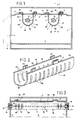
- the cooking appliance shown in FIG. 1 is a household oven having a cooking enclosure 1 which is open on its front face and the internal wall of which forms the vault 3, the bottom 4, the bottom 5 and the two sides 6 and 7, said front face being able to be closed by a door 8 (shown diagrammatically in broken lines).
- This cooking chamber 1 comprises at least one electrical heating element 9 comprising a tubular casing 10 of fragile material of the quartz or glass type, which contains a heating wire 11 and the ends 12 and 13 of which are connected respectively to two plugs 14 and 15 each disposed at one end of the envelope, each plug 14, 15 being adapted to be mounted in a support 16, 17 secured to said enclosure 1 so as to keep said envelope 10 away from the internal wall of the enclosure.
- electrical heating element 9 comprising a tubular casing 10 of fragile material of the quartz or glass type, which contains a heating wire 11 and the ends 12 and 13 of which are connected respectively to two plugs 14 and 15 each disposed at one end of the envelope, each plug 14, 15 being adapted to be mounted in a support 16, 17 secured to said enclosure 1 so as to keep said envelope 10 away from the internal wall of the enclosure.
- the cooking chamber 1 contains two heating elements 9, the tubular casing 10 of which has the shape of a straight rod, the plugs 14 and 15 being supported by the supports 16 and 17 arranged on the sides 6 and 7 of the enclosure 1 so as to keep the two envelopes 10 parallel to each other and at a distance from the arch 3.
- the elements 9 shown are of the quartz envelope type, but could also be of the glass envelope halogen type.
- the tubular casing 10 of the heating element 9 is enclosed in a cage 18 whose wall 19 is sufficiently perforated to allow the infrared radiation to pass inside the enclosure 1, and sufficiently rigid to resist a possible mechanical shock, said cage 18 comprising fixing means on the wall internal speaker.
- the cage 18 is preferably made of sheet metal and has a grounding lug P intended to be electrically connected to the enclosure 1, for example, by means of a screw.
- the cage 18 has the shape of a gutter whose wall 19 has perforations 20 and overlaps at a distance the side wall 21 of the tubular casing 10 facing the inside of the enclosure, and whose longitudinal edges 22, 23 include the fixing means.
- the fixing means are formed by lugs 24, 25 formed on the longitudinal edges 22 and 23 of the gutter, while the inner wall of the enclosure forming the vault 3 has slots 26 adapted to receive the pins 24 and 25 as well as the grounding lug P.
- the lugs 24, 25 are deformed by twisting to bring them in a direction transverse to the slots 26 (position illustrated in solid lines in Figure 1 and in broken lines in Figure 3 ). Then the flap P is folded down by folding on the arch 3, and the electrical connection for grounding is provided by means of the screw.
- the wall of the enclosure in this case the arch 3 , includes bosses 27 located respectively near the slots 26 on which come to bear, after twisting, said pins.
- the bottom of the gutter has an unperforated area 28 extending longitudinally to said envelope, while the perforations 20 are formed by lights oblong arranged transversely to the tubular casing 10 and symmetrically with respect to this area 28.
- the lights 20 in order to meet current safety standards, it has been chosen to give the lights 20 a width of less than five millimeters, and at the distance d between the internal face of the gutter and the side wall 21 of the casing 10. a value greater than four millimeters.
Landscapes
- Engineering & Computer Science (AREA)
- Chemical & Material Sciences (AREA)
- Combustion & Propulsion (AREA)
- Mechanical Engineering (AREA)
- General Engineering & Computer Science (AREA)
- Electric Stoves And Ranges (AREA)
- Resistance Heating (AREA)
- Cookers (AREA)
- Baking, Grill, Roasting (AREA)
- Control Of Resistance Heating (AREA)
- General Preparation And Processing Of Foods (AREA)
- Formation And Processing Of Food Products (AREA)
- Confectionery (AREA)
- Thermistors And Varistors (AREA)
Description
- L'invention se rapporte aux appareils de cuisson tels que, par exemple, des fours comprenant une enceinte de cuisson ouverte sur sa face frontale et comportant au moins un élément électrique de chauffage ayant une enveloppe tubulaire en matériau fragile du type quartz ou verre, qui présente la forme d'un barreau droit et qui contient un fil chauffant et dont les extrémités sont reliées respectivement à deux bouchons disposés chacun à une extrémité de l'enveloppe, chaque bouchon étant adapté à être monté dans un support solidaire de ladite enceinte de manière à maintenir ladite enveloppe à distance de la paroi interne formant la voûte de l'enceinte.
- De tels fours à éléments électriques de chauffage à enveloppes fragiles sont connus par les documents EP-A-266 134 et EP-A-251 539.
- D'après le document EP-A-266 134, l'enveloppe tubulaire en quartz est protégée mécaniquement par un cache métallique maillé s'étendant longitudinalement en dessous de l'enveloppe et sensiblement à mi-hauteur de chaque côté de l'enveloppe. Par cette disposition du cache, il existe le risque d'un endommagement de la portion découverte de l'enveloppe sous l'effet d'un choc mécanique, de sorte que ce cache n'assure pas une protection mécanique complète de l'enveloppe.
- Le document EP-A-251 539 décrit un appareil de cuisson comportant deux tubes infrarouges à enveloppe tubulaire en quartz, qui sont montés dans un même compartiment séparé de la zone de cuisson par un écran plat commun aux deux tubes et destiné à protéger ceux-ci contre les chocs mécaniques. Toutefois, le fait que cet écran protège collectivement les deux tubes infrarouges s'avère inapproprié car en cas de changement de l'un des deux tubes pour cause de défaillance, l'autre tube n'est plus protégé en soi et risque d'être endommagé par suite d'une mauvaise manipulation du réparateur changeant le tube défaillant.
- L'invention a pour but de remédier à ces inconvénients et de réaliser une même pièce individuelle qui assure une protection mécanique complète de chacune des enveloppes tubulaires en matériau fragile de manière à satisfaire aux normes actuelles de sécurité exigeant une protection mécanique des éléments de chauffage, et qui puisse être montée de manière facile et sûre sur la voûte de l'enceinte de cuisson du four.
- Selon l'invention, un appareil de cuisson du type décrit précédemment, est plus particulièrement caractérisé en ce que l'enveloppe tubulaire est enfermée dans une cage présentant la forme d'une gouttière dont la paroi, d'une part, comporte des perforations pour laisser passer le rayonnement infrarouge vers l'intérieur de l'enceinte et est suffisamment rigide pour résister à un éventuel choc mécanique, et d'autre part, chevauche à distance la paroi latérale de l'enveloppe tubulaire tournée vers l'intérieur de l'enceinte, et dont les bords longitudinaux comportent des moyens de fixation directe de la cage sur la voûte de l'enceinte.
- Ainsi, l'enveloppe tubulaire fragile est entièrement protégée contre tout choc ou manipulation de l'utilisateur, et l'élément de chauffage satisfait ainsi aux normes de sécurité.
- En outre, un autre avantage lié à cette protection de l'enveloppe est la possibilité pour le fabricant d'utiliser un élément de chauffage à enveloppe quartz dont l'épaisseur est voisine de un millimètre au lieu des deux millimètres ordinairement proposés, et donc de diminuer le prix de revient de l'élément de chauffage.
- Les caractéristiques et avantages de l'invention ressortiront d'ailleurs de la description qui va suivre, à titre d'exemple, en référence au dessin annexé dans lequel :
- la Figure 1 est une coupe verticale schématique d'un appareil de cuisson selon l'invention et illustrant deux éléments de chauffage enfermés respectivement dans deux cages de protection ;
- la Figure 2 représente en perspective et à plus grande échelle une cage de protection selon l'invention ;
- la Figure 3 est une coupe partielle verticale selon la ligne III-III de la Figure 1, mais avec la cage non encore fixée définitivement sur l'enceinte.
- L'appareil de cuisson représenté à la Figure 1 est un four ménager présentant une enceinte de cuisson 1 qui est ouverte sur sa face frontale et dont la paroi interne forme la voûte 3, la sole 4, le fond 5 et les deux côtés 6 et 7, ladite face frontale pouvant être fermée par une porte 8 (schématisée en traits interrompus).
- Cette enceinte de cuisson 1 comprend au moins un élément électrique de chauffage 9 comportant une enveloppe tubulaire 10 en matériau fragile du type quartz ou verre, qui contient un fil chauffant 11 et dont les extrémités 12 et 13 sont reliées respectivement à deux bouchons 14 et 15 disposés chacun à une extrémité de l'enveloppe, chaque bouchon 14, 15 étant adapté à être monté dans un support 16, 17 solidaire de ladite enceinte 1 de manière à maintenir ladite enveloppe 10 à distance de la paroi interne de l'enceinte.
- Comme on le voit et de manière à obtenir un meilleur chauffage, l'enceinte de cuisson 1 contient deux éléments de chauffage 9 dont l'enveloppe tubulaire 10 présente la forme d'un barreau droit, les bouchons 14 et 15 étant supportés par les supports 16 et 17 agencés sur les côtés 6 et 7 de l'enceinte 1 de manière à maintenir les deux enveloppes 10 parallèles entre elles et à distance de la voûte 3.
- Les éléments 9 représentés sont du type à enveloppe quartz, mais pourraient aussi être du type à halogène à enveloppe verre.
- Selon l'invention, l'enveloppe tubulaire 10 de l'élément de chauffage 9 est enfermée dans une cage 18 dont la paroi 19 est suffisamment ajourée pour laisser passer le rayonnement infrarouge vers l'intérieur de l'enceinte 1, et suffisamment rigide pour résister à un éventuel choc mécanique, ladite cage 18 comportant des moyens de fixation sur la paroi interne de l'enceinte. La cage 18 est de préférence réalisée en tôle et comporte une patte P de mise à la terre destinée à être reliée électriquement à l'enceinte 1, par exemple, au moyen d'une vis.
- La cage 18 présente la forme d'une gouttière dont la paroi 19 présente des perforations 20 et chevauche à distance la paroi latérale 21 de l'enveloppe tubulaire 10 tournée vers l'intérieur de l'enceinte, et dont les bords longitudinaux 22, 23 comportent les moyens de fixation.
Comme on le voit mieux sur la Figure 2, les moyens de fixation sont formés par des ergots 24, 25 pratiqués sur les bords longitudinaux 22 et 23 de la gouttière, tandis que la paroi interne de l'enceinte formant la voûte 3 présente des fentes 26 adaptées à recevoir les ergots 24 et 25 ainsi que la patte P de mise à la terre. - Pour fixer la cage 18 contre la voûte 3, on procède à une déformation des ergots 24, 25 par torsion pour les amener dans une direction transversale aux fentes 26 (position illustrée en traits plein sur la Figure 1 et en traits interrompus sur la Figure 3). Puis on rabat la patte P par pliage sur la voûte 3, et on assure au moyen de la vis la connexion électrique de mise à la terre.
- Pour garantir l'application des bords 22 et 23 de la gouttière contre la voûte 3 et rattraper un éventuel jeu dû au découpage industriel des ergots et de la tôle constituant la cage, la paroi de l'enceinte, dans le cas présent la voûte 3, comporte des bossages 27 situés respectivement à proximité des fentes 26 sur lesquelles viennent s'appuyer, après torsion, lesdits ergots.
- Pour garantir une certaine rigidité à la cage 18 tout en réduisant au minimum le rayonnement infrarouge nécessaire à la cuisson, le fond de la gouttière présente une plage 28 non perforée s'étendant longitudinalement à ladite enveloppe, tandis que les perforations 20 sont formées par des lumières oblongues disposées transversalement à l'enveloppe tubulaire 10 et symétriquement par rapport à cette plage 28.
- En outre, de manière à satisfaire aux normes de sécurité actuelles, on a choisi de donner aux lumières 20 une largeur inférieure à cinq millimètres, et à la distance d entre la face interne de la gouttière et la paroi latérale 21 de l'enveloppe 10 une valeur supérieure à quatre millimètres.
- Ainsi, comme on le comprendra, grâce à la cage 18 qui prend appui sur la voûte 3, on obtient une protection efficace contre tout choc mécanique éventuel et également contre des coups appliqués par "un appareil de choc à ressort" destiné à vérifier la conformité aux normes du four.
- En outre, grâce à cette cage 18, on peut réduire, dans le cas des enveloppes en quartz, l'épaisseur de ladite enveloppe afin d'utiliser des tubes moins onéreux, par exemple, on choisit une épaisseur de un millimètre au lieu de deux. Bien entendu, on pourra prévoir une cage unique enveloppant deux enveloppes parallèles, une cage formée d'un treillis métallique ou de tôle déployée et d'autres moyens de fixation contre l'une des parois de l'enceinte.
Claims (6)
- Appareil de cuisson tel que, par exemple, un four comprenant une enceinte de cuisson (1) ouverte sur sa face frontale et comportant au moins un élément électrique (9) de chauffage ayant une enveloppe tubulaire (10) en matériau fragile du type quartz ou verre, qui présente la forme d'un barreau droit et qui contient un fil chauffant (11) et dont les extrémités (12 et 13) sont reliées respectivement à deux bouchons (14 et 15) disposés chacun à une extrémité de l'enveloppe, chaque bouchon étant adapté à être monté dans un support (16, 17) solidaire de ladite enceinte (1) de manière à maintenir ladite enveloppe (10) à distance de la paroi interne formant la voûte (3) de l'enceinte,
caractérisé en ce que l'enveloppe tubulaire (10) est enfermée dans une cage (18) présentant la forme d'une gouttière dont la paroi (19), d'une part, comporte des perforations (20) pour laisser passer le rayonnement infrarouge vers l'intérieur de l'enceinte (1) et est suffisamment rigide pour résister à un éventuel choc mécanique, et d'autre part, chevauche à distance la paroi latérale (21) de l'enveloppe tubulaire (10) tournée vers l'intérieur de l'enceinte, et dont les bords longitudinaux (22,23) comportent des moyens de fixation directe (24,25) de la cage (18) sur la voûte (3) de l'enceinte. - Appareil de cuisson selon la revendication 1,
caractérisé en ce que les perforations (20) sont formées par des lumières oblongues disposées transversalement à l'enveloppe tubulaire (10). - Appareil de cuisson selon la revendication 2,
caractérisé en ce que le fond de la gouttière présente une plage (28) non perforée s'étendant longitudinalement à l'enveloppe tubulaire (10), les lumières (20) étant disposées symétriquement par rapport à cette plage. - Appareil de cuisson selon la revendication 2 ou 3,
caractérisé en ce que la largeur des lumières (20) est inférieure à cinq millimètres et la distance d entre la face interne de la gouttière et la paroi latérale (21) de l'enveloppe tubulaire (10) est supérieure à quatre millimètres. - Appareil de cuisson selon l'une quelconque des revendications précédentes,
caractérisé en ce que la cage (18) est réalisée en tôle et comporte en outre une patte (P) de mise à la terre destinée à être reliée électriquement à l'enceinte (1). - Appareil de cuisson selon l'une quelconque des revendication précédentes,
caractérisé en ce que les moyens de fixation (24, 25) sont formés par des ergots pratiqués sur les bords longitudinaux (22, 23) de la gouttière, tandis que la voûte (3) de l'enceinte (1) présente des fentes (26) adaptées à recevoir lesdits ergots, la cage (18) étant fixée sur la voûte (3) de l'enceinte (1) par déformation des ergots pour les amener dans une direction transversale aux fentes (26).
Applications Claiming Priority (2)
| Application Number | Priority Date | Filing Date | Title |
|---|---|---|---|
| FR9100480A FR2671859B1 (fr) | 1991-01-17 | 1991-01-17 | Appareil de cuisson, par exemple four comportant un protecteur pour un element chauffant electrique. |
| FR9100480 | 1991-01-17 |
Publications (3)
| Publication Number | Publication Date |
|---|---|
| EP0495394A2 EP0495394A2 (fr) | 1992-07-22 |
| EP0495394A3 EP0495394A3 (en) | 1992-10-14 |
| EP0495394B1 true EP0495394B1 (fr) | 1995-04-12 |
Family
ID=9408764
Family Applications (1)
| Application Number | Title | Priority Date | Filing Date |
|---|---|---|---|
| EP92100267A Expired - Lifetime EP0495394B1 (fr) | 1991-01-17 | 1992-01-09 | Appareil de cuisson, par exemple four comportant un protecteur pour élément chauffant électrique |
Country Status (10)
| Country | Link |
|---|---|
| US (1) | US5196674A (fr) |
| EP (1) | EP0495394B1 (fr) |
| KR (1) | KR100208871B1 (fr) |
| AT (1) | ATE121180T1 (fr) |
| CA (1) | CA2059509A1 (fr) |
| DE (1) | DE69201963T2 (fr) |
| ES (1) | ES2073187T3 (fr) |
| FR (1) | FR2671859B1 (fr) |
| MX (1) | MX9200191A (fr) |
| PT (1) | PT100019B (fr) |
Families Citing this family (16)
| Publication number | Priority date | Publication date | Assignee | Title |
|---|---|---|---|---|
| DE4243993C2 (de) * | 1992-12-23 | 1998-11-19 | Bosch Siemens Hausgeraete | Elektrischer Toaster |
| SE510965C2 (sv) * | 1997-11-10 | 1999-07-12 | Efo Fasadteknik Int | Anordning för uppmjukning av färg med värmestrålning från motståndstrådar |
| RU2121625C1 (ru) * | 1998-04-03 | 1998-11-10 | Ванцов Валерий Матвеевич | Электропечь |
| GB2349454A (en) * | 1999-03-26 | 2000-11-01 | Counterline Limited | Radiant heater for food display unit with infrared source and emitter plate |
| US7067770B1 (en) | 1999-11-09 | 2006-06-27 | Centrotherm Elektrische Anlagen Gmbh & Co. | Radiant heating system with a high infrared radiant heating capacity, for treatment chambers |
| KR100390490B1 (ko) * | 2000-04-19 | 2003-07-04 | 엘지전자 주식회사 | 전자렌지의 히팅장치 |
| US6595663B2 (en) * | 2001-02-07 | 2003-07-22 | Frank Tsao | Work light cage attachment system |
| CN2522765Y (zh) * | 2001-12-13 | 2002-11-27 | 广东德豪润达电气股份有限公司 | 光波烤箱 |
| CN2822463Y (zh) * | 2005-02-19 | 2006-10-04 | 王冬雷 | 一种多士炉 |
| GB2452336A (en) * | 2007-09-03 | 2009-03-04 | James Hattrick | Clamping means for cooker hotplate |
| FR2947990B1 (fr) * | 2009-07-16 | 2011-09-16 | Centre Nat Rech Scient | Four de cuisson a usage alimentaire et procede de cuisson d'une pate a base de cereales |
| KR101276498B1 (ko) * | 2011-07-21 | 2013-06-18 | 엘지전자 주식회사 | 드로워 유닛 및 이를 포함하는 전기 오븐 |
| EP2807967A1 (fr) * | 2013-05-31 | 2014-12-03 | Spectrum Brands, Inc. | Gril de plateau de table |
| KR101749116B1 (ko) | 2015-05-08 | 2017-06-20 | 엘지전자 주식회사 | 조리기기 |
| CN107655045B (zh) * | 2017-09-26 | 2024-03-08 | 浙江爱隆电器有限公司 | 一种电陶炉 |
| US11598529B2 (en) * | 2019-03-05 | 2023-03-07 | Whirlpool Corporation | Oven burner cover screen with improved mesh configuration |
Family Cites Families (13)
| Publication number | Priority date | Publication date | Assignee | Title |
|---|---|---|---|---|
| US1118827A (en) * | 1912-11-26 | 1914-11-24 | Bryant Electric Co | Electrical fitting. |
| US1496811A (en) * | 1922-11-02 | 1924-06-10 | Walter W Lange | Crossing signal |
| US2081395A (en) * | 1936-05-14 | 1937-05-25 | Trumbull Electric Mfg Co | Electric chicken brooder |
| US2337745A (en) * | 1941-07-26 | 1943-12-28 | Electronic Lab Inc | Lamp and receptacle therefor |
| US3059086A (en) * | 1959-05-28 | 1962-10-16 | Norman E Pedersen | Radiant heater and method of operating the same |
| US3163842A (en) * | 1962-01-29 | 1964-12-29 | John C Wittwer | Housing for electrical unit |
| US3204085A (en) * | 1962-08-15 | 1965-08-31 | Lockheed Aircraft Corp | Heating device |
| US4267429A (en) * | 1979-03-08 | 1981-05-12 | Brown Group, Inc. | Apparatus for activating shoe assembly cement |
| DE3035712C2 (de) * | 1980-09-22 | 1984-09-13 | Bosch-Siemens Hausgeräte GmbH, 7000 Stuttgart | Elektrischer Brotröster |
| GB8615201D0 (en) * | 1986-06-21 | 1986-07-23 | Thorn Emi Appliances | Grilling/browning food |
| EP0266134A1 (fr) * | 1986-10-29 | 1988-05-04 | THORN EMI Patents Limited | Appareil pour griller ou dorer des aliments |
| GB2210968A (en) * | 1987-10-07 | 1989-06-21 | Strinex Ind Limited | Radiant heating or lighting apparatus |
| US4885670A (en) * | 1988-04-04 | 1989-12-05 | K & H Industries, Inc. | Portable lamp |
-
1991
- 1991-01-17 FR FR9100480A patent/FR2671859B1/fr not_active Expired - Fee Related
-
1992
- 1992-01-09 EP EP92100267A patent/EP0495394B1/fr not_active Expired - Lifetime
- 1992-01-09 DE DE69201963T patent/DE69201963T2/de not_active Expired - Fee Related
- 1992-01-09 ES ES92100267T patent/ES2073187T3/es not_active Expired - Lifetime
- 1992-01-09 AT AT92100267T patent/ATE121180T1/de not_active IP Right Cessation
- 1992-01-10 US US07/819,130 patent/US5196674A/en not_active Expired - Fee Related
- 1992-01-16 CA CA002059509A patent/CA2059509A1/fr not_active Abandoned
- 1992-01-16 PT PT100019A patent/PT100019B/pt not_active IP Right Cessation
- 1992-01-16 MX MX9200191A patent/MX9200191A/es not_active IP Right Cessation
- 1992-01-17 KR KR1019920000649A patent/KR100208871B1/ko not_active Expired - Fee Related
Also Published As
| Publication number | Publication date |
|---|---|
| KR100208871B1 (ko) | 1999-07-15 |
| KR920015076A (ko) | 1992-08-26 |
| DE69201963T2 (de) | 1995-09-07 |
| DE69201963D1 (de) | 1995-05-18 |
| FR2671859A1 (fr) | 1992-07-24 |
| US5196674A (en) | 1993-03-23 |
| ES2073187T3 (es) | 1995-08-01 |
| EP0495394A2 (fr) | 1992-07-22 |
| CA2059509A1 (fr) | 1992-07-18 |
| PT100019A (pt) | 1994-04-29 |
| ATE121180T1 (de) | 1995-04-15 |
| MX9200191A (es) | 1992-07-01 |
| PT100019B (pt) | 1999-02-26 |
| FR2671859B1 (fr) | 1999-01-22 |
| EP0495394A3 (en) | 1992-10-14 |
Similar Documents
| Publication | Publication Date | Title |
|---|---|---|
| EP0495394A2 (fr) | Appareil de cuisson, par exemple four comportant un protecteur pour élément chauffant électrique | |
| EP0735324B1 (fr) | Porte de four simplifiée avec module amovible | |
| FR2539021A1 (fr) | Appareil culinaire pour preparer des sandwichs du genre dit " hamburgers " | |
| FR2799632A1 (fr) | Grille pain | |
| FR2644636A1 (fr) | Porte-balais pour machine electrique a courant continu, en particulier pour le moteur electrique d'un ventilateur electrique pour refroidir le radiateur d'un moteur a combustion interne | |
| FR2699389A1 (fr) | Grille-pain électrique. | |
| EP4102120A1 (fr) | Dispositif de passage d'éléments filiformes | |
| FR2673350A1 (fr) | Guide d'ondes pour four a micro-ondes. | |
| EP0691668B1 (fr) | Sous-ensemble thermique pour disjoncteur | |
| CH643647A5 (fr) | Appareil electrique de chauffage. | |
| FR2844694A1 (fr) | Capot d'appareil electrique du type gaufrier | |
| FR2767911A1 (fr) | Support de corps de chauffe | |
| FR2489684A1 (fr) | Grille-pain electrique | |
| FR2657214A1 (fr) | Gril electrique. | |
| FR2740318A1 (fr) | Grille-pain electrique | |
| EP1434009A1 (fr) | Support de broche, équipement comprenant un tel support et four électroménager comprenant un tel équipement. | |
| FR2608883A1 (fr) | Element resistant chauffant decoupe pour radiateur electrique, son procede de fabrication et radiateur s'y rapportant | |
| EP0082972A2 (fr) | Appareil électrique de cuisson, tel qu'un four ménager | |
| EP0919172B1 (fr) | Appareil électrique de cuisson | |
| FR3001791B1 (fr) | Dispositif pour la generation d'un rideau d'air chaud | |
| CH356550A (fr) | Appareil à broche tournante pour cuire des aliments | |
| BE418771A (fr) | ||
| CH369869A (fr) | Rôtissoire | |
| CH594395A5 (en) | Cooking spit with hollow rod attached to handle | |
| BE528156A (fr) |
Legal Events
| Date | Code | Title | Description |
|---|---|---|---|
| PUAI | Public reference made under article 153(3) epc to a published international application that has entered the european phase |
Free format text: ORIGINAL CODE: 0009012 |
|
| AK | Designated contracting states |
Kind code of ref document: A2 Designated state(s): AT BE CH DE ES GB LI NL SE |
|
| PUAL | Search report despatched |
Free format text: ORIGINAL CODE: 0009013 |
|
| AK | Designated contracting states |
Kind code of ref document: A3 Designated state(s): AT BE CH DE ES GB LI NL SE |
|
| 17P | Request for examination filed |
Effective date: 19930413 |
|
| 17Q | First examination report despatched |
Effective date: 19931122 |
|
| GRAA | (expected) grant |
Free format text: ORIGINAL CODE: 0009210 |
|
| AK | Designated contracting states |
Kind code of ref document: B1 Designated state(s): AT BE CH DE ES GB LI NL SE |
|
| REF | Corresponds to: |
Ref document number: 121180 Country of ref document: AT Date of ref document: 19950415 Kind code of ref document: T |
|
| REF | Corresponds to: |
Ref document number: 69201963 Country of ref document: DE Date of ref document: 19950518 |
|
| GBT | Gb: translation of ep patent filed (gb section 77(6)(a)/1977) |
Effective date: 19950427 |
|
| REG | Reference to a national code |
Ref country code: ES Ref legal event code: FG2A Ref document number: 2073187 Country of ref document: ES Kind code of ref document: T3 |
|
| PLBE | No opposition filed within time limit |
Free format text: ORIGINAL CODE: 0009261 |
|
| STAA | Information on the status of an ep patent application or granted ep patent |
Free format text: STATUS: NO OPPOSITION FILED WITHIN TIME LIMIT |
|
| 26N | No opposition filed | ||
| PGFP | Annual fee paid to national office [announced via postgrant information from national office to epo] |
Ref country code: CH Payment date: 19981224 Year of fee payment: 8 |
|
| PGFP | Annual fee paid to national office [announced via postgrant information from national office to epo] |
Ref country code: GB Payment date: 19990104 Year of fee payment: 8 |
|
| PGFP | Annual fee paid to national office [announced via postgrant information from national office to epo] |
Ref country code: ES Payment date: 19990128 Year of fee payment: 8 |
|
| PGFP | Annual fee paid to national office [announced via postgrant information from national office to epo] |
Ref country code: NL Payment date: 19990129 Year of fee payment: 8 |
|
| PGFP | Annual fee paid to national office [announced via postgrant information from national office to epo] |
Ref country code: BE Payment date: 19990324 Year of fee payment: 8 |
|
| PG25 | Lapsed in a contracting state [announced via postgrant information from national office to epo] |
Ref country code: GB Free format text: LAPSE BECAUSE OF NON-PAYMENT OF DUE FEES Effective date: 20000109 |
|
| PG25 | Lapsed in a contracting state [announced via postgrant information from national office to epo] |
Ref country code: ES Free format text: LAPSE BECAUSE OF NON-PAYMENT OF DUE FEES Effective date: 20000110 |
|
| PG25 | Lapsed in a contracting state [announced via postgrant information from national office to epo] |
Ref country code: LI Free format text: LAPSE BECAUSE OF NON-PAYMENT OF DUE FEES Effective date: 20000131 Ref country code: CH Free format text: LAPSE BECAUSE OF NON-PAYMENT OF DUE FEES Effective date: 20000131 Ref country code: BE Free format text: LAPSE BECAUSE OF NON-PAYMENT OF DUE FEES Effective date: 20000131 |
|
| BERE | Be: lapsed |
Owner name: S.A. MOULINEX Effective date: 20000131 |
|
| PG25 | Lapsed in a contracting state [announced via postgrant information from national office to epo] |
Ref country code: NL Free format text: LAPSE BECAUSE OF NON-PAYMENT OF DUE FEES Effective date: 20000801 |
|
| GBPC | Gb: european patent ceased through non-payment of renewal fee |
Effective date: 20000109 |
|
| REG | Reference to a national code |
Ref country code: CH Ref legal event code: PL |
|
| NLV4 | Nl: lapsed or anulled due to non-payment of the annual fee |
Effective date: 20000801 |
|
| REG | Reference to a national code |
Ref country code: ES Ref legal event code: FD2A Effective date: 20010910 |
|
| PGFP | Annual fee paid to national office [announced via postgrant information from national office to epo] |
Ref country code: AT Payment date: 20020114 Year of fee payment: 11 |
|
| PGFP | Annual fee paid to national office [announced via postgrant information from national office to epo] |
Ref country code: SE Payment date: 20020125 Year of fee payment: 11 |
|
| PGFP | Annual fee paid to national office [announced via postgrant information from national office to epo] |
Ref country code: DE Payment date: 20020207 Year of fee payment: 11 |
|
| PG25 | Lapsed in a contracting state [announced via postgrant information from national office to epo] |
Ref country code: AT Free format text: LAPSE BECAUSE OF NON-PAYMENT OF DUE FEES Effective date: 20030109 |
|
| PG25 | Lapsed in a contracting state [announced via postgrant information from national office to epo] |
Ref country code: SE Free format text: LAPSE BECAUSE OF NON-PAYMENT OF DUE FEES Effective date: 20030110 |
|
| PG25 | Lapsed in a contracting state [announced via postgrant information from national office to epo] |
Ref country code: DE Free format text: LAPSE BECAUSE OF NON-PAYMENT OF DUE FEES Effective date: 20030801 |
|
| EUG | Se: european patent has lapsed |