EP0492127B1 - Traversée pour dispositifs de commutation isolés par gaz sous pression - Google Patents
Traversée pour dispositifs de commutation isolés par gaz sous pression Download PDFInfo
- Publication number
- EP0492127B1 EP0492127B1 EP91119617A EP91119617A EP0492127B1 EP 0492127 B1 EP0492127 B1 EP 0492127B1 EP 91119617 A EP91119617 A EP 91119617A EP 91119617 A EP91119617 A EP 91119617A EP 0492127 B1 EP0492127 B1 EP 0492127B1
- Authority
- EP
- European Patent Office
- Prior art keywords
- cone
- joining piece
- current
- inner conductor
- bushing according
- Prior art date
- Legal status (The legal status is an assumption and is not a legal conclusion. Google has not performed a legal analysis and makes no representation as to the accuracy of the status listed.)
- Expired - Lifetime
Links
Images

Classifications
-
- H—ELECTRICITY
- H01—ELECTRIC ELEMENTS
- H01B—CABLES; CONDUCTORS; INSULATORS; SELECTION OF MATERIALS FOR THEIR CONDUCTIVE, INSULATING OR DIELECTRIC PROPERTIES
- H01B17/00—Insulators or insulating bodies characterised by their form
- H01B17/26—Lead-in insulators; Lead-through insulators
Definitions
- the invention relates to a bushing for pressurized gas-insulated switchgear assemblies according to the preamble of claim 1.
- Such bushings are used in gas-insulated switchgear gas-tight in the housing walls of these systems. After installing a system, it is necessary to subject the connected cables to a voltage test. It is already known that separate feedthroughs are additionally used for the testing of the cables, which are externally connected to a grounding rail in three phases and represent part of the inner grounding switch due to contacts placed in the interior of the system. With this construction, the outer earthing bar can be removed and the internal switch switched into the attached contacts on the inside, whereby a cable test can be carried out in this switching state. In this context, removing the external earth connection can result in a safety-threatening state. Otherwise, the arrangement described above is very expensive and the assignment is difficult to recognize.
- the invention specified in claim 1 is therefore based on the problem of creating an implementation that allows a simple test of the cable connected to the implementation while increasing the security and reducing the parts required for this.
- standard plugs and end closure fittings should be able to be connected to the bushing without great effort.
- a lateral adapter is introduced by a small spatial enlargement of the bushing, the inner conductor of which can be connected on the one hand to the current-carrying inner conductor of the bushing in a simple and electrically tight manner and on the other hand a connection for testing the cable provides.
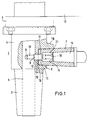
- a device connection part 1 is fastened with its fastening flange 2 to a switchgear assembly 17 .
- a section 4 adjoins the mounting flange 2 and is predominantly cylindrical. In extension of this section 4 , a conical section 3 is arranged, which serves to connect a plug or a cable set (not shown).
- a current-carrying inner conductor 5 designed as a lead-through bolt is inserted axially in the device connection part 1 .
- section 4 there is a lateral opening 6 which serves to accommodate an adapter 7 .
- This adapter 7 contains an inner conductor 8 , which is designed as a threaded stud bolt 12, 13, 14 .
- an externally threaded part is connected to the shoulder 12 of the threaded stud bolt 13 and on the other hand an internal thread part 14 .
- the adapter 7 has a bottom 10 with an axial bore 11 , which is designed such that the shoulder 12 of the threaded stud bolt 12, 13, 14 has a firm fit in the ground 10 of the adapter 7 has.
- the external thread part 13 engages in a threaded blind hole 9 of the current-carrying inner conductor 5
- the internal thread part 14 which has the same internal diameter as the external diameter of the external thread part 13 , serves to receive an external thread 16 of an insulating plug 15 .
- the lateral opening 6 of the device connection part 1 has a blind hole-like shape 19 which merges into an axial bore 20 in the region of the extension 12 .
- the design of the adapter 7 as a hollow cone means that the internal thread part 14 also has an external conical shape 21 which is adapted to the internal cone of the adapter 7 .
- the cone of the adapter 7 is guided up to the current-carrying inner conductor 5 of the device connection part 1 .
- a continuous threaded bore 22 is made in the current-carrying inner conductor 5 in order to be able to accommodate the elongated external thread part 13 .
- a double cone 23 is screwed into the current-carrying conductor 5 as a cable test connection.
- the double cone 23 is made of silicone rubber and has a shoulder bolt 24 made of electrolytic copper.
- the shoulder bolt 24 has a threaded part 25 on the side facing the current-carrying inner conductor 5 and a threaded part 26 for receiving a wing nut 27 on the side facing away from the current-carrying inner conductor 5 .
- the shoulder bolt 24 has a driving ring 28 which is screwed onto the shoulder bolt 24 and is cast by the silicone of the double cone 23 .
- the opening 6 in the device connection part 1 is closed by a molded part 29 made of insulating material.
- This molded part 29 is cast in a silicone rubber cone 30 , a driving ring 31 being provided for the silicone part (cast in the molded part 29 ).
Landscapes
- Gas-Insulated Switchgears (AREA)
- Cable Accessories (AREA)
Claims (13)
- Traversée pour dispositifs de commutation étanches aux gaz, avec une pièce de connexion qu'on peut fixer dans une paroi de boîtier du dispositif de commutation, qui comprend une bride de fixation et se termine par une partie en forme de cône, et avec un conducteur intérieur conduisant le courant, qui est disposé axialement dans la pièce de connexion, caractérisée en ce que la pièce de connexion (1) entre la bride de fixation (2) et la partie en forme de cône (3) est munie d'une pièce (4) qui présente un orifice (6) latéral allant jusqu'au conducteur intérieur (5) conduisant le courant, et qu'on peut insérer dans cet orifice (6) un adaptateur (7) dont le conducteur intérieur (8) peut être relié électriquement au conducteur intérieur (5) de la pièce de connexion (1).
- Traversée selon la revendication 1, caractérisée en ce que le conducteur intérieur (5) conduisant le courant est en forme de goujon traversant, qui passe dans la pièce (4) de la pièce de connexion (1) par un trou borgne fileté (9) dont l'axe est perpendiculaire à l'axe du conducteur intérieur conduisant le courant (5).
- Traversée selon l'une des revendications 1 ou 2, caractérisée en ce que l'adaptateur (7) est en forme de cône creux fermé d'un côté en caoutchouc silicone, dont le fond (10) est muni d'un trou (11), et que dans le cône est inséré un conducteur intérieur en forme de goujon fileté à prolongement (12, 13, 14) dont le prolongement (12) est muni d'une pièce filetée à l'extérieur (13) du côté tourné vers le conducteur intérieur (5) conduisant le courant et à l'intérieur du cône d'une pièce filetée à l'intérieur (14).
- Traversée selon l'une des revendications 1 à 3, caractérisée en ce que l'adaptateur (7) est obturable avec un tampon isolant (15), qui présente du côté tourné vers le goujon à prolongement fileté (12, 13, 14) un filetage extérieur (16) correspondant au filetage intérieur (14) du goujon à prolongement fileté (12, 13, 14).
- Traversée selon l'une des revendications 1 à 4, caractérisée en ce que la pièce de connexion (1) peut être fixée au dispositif de commutation (17) de sorte que l'orifice latéral (6) dans la pièce (4) se présente en différentes orientations angulaires.
- Traversée selon l'une des revendications 1 à 5, caractérisée en ce que la pièce (4) se présente avec un évasement latéral (18) pour prolonger l'intervalle d'étanchéité.
- Traversée selon l'une des revendications 1 à 6, caractérisée en ce que l'orifice latéral (6) dans la pièce (4) de la pièce de connexion (1) présente une forme en trou borgne conique à l'intérieur (19) avec un trou axial (20) pour le prolongement (12) du goujon fileté à prolongement (12, 13, 14).
- Traversée selon la revendication 1, caractérisée en ce que l'orifice latéral (6) dans la pièce (4) de la pièce de connexion (1) présente une forme appropriée à l'adaptateur (7) conique à l'intérieur allant jusqu'au conducteur intérieur (5) conduisant le courant de la pièce de connexion (1) et que le trou fileté (22) est traversant dans le conducteur intérieur (5) conduisant le courant.
- Traversée selon la revendication 8, caractérisée en ce que la pièce filetée à l'intérieur (14) présente un cône extérieur (21) correspondant au cône intérieur de l'adaptateur (7).
- Traversée selon la revendication 1, caractérisée en ce que l'adaptateur (7) est en forme de double cône (24) dans l'intérieur duquel est inséré le goujon de fixation (24), qui est muni des deux côtés d'une pièce filetée (25, 26), dont une partie filetée (25) est vissable sur le filetage intérieur du conducteur (5) conduisant le courant, et l'autre partie filetée (26) est munie d'un écrou à oreilles (27) et que le goujon de fixation (25) est renforcé dans le cône double (23) par une bague d'entraînement (28) à l'intérieur du cône double (23), et il vient en prise dans le double cône en caoutchouc silicone.
- Traversée selon la revendication 10, caractérisée en ce que la bague d'entraînement (28) est surmoulée dans le caoutchouc silicone du double cône (23).
- Traversée selon l'une des revendications 10 ou 11, caractérisée en ce que l'orifice latéral (6) de la pièce de connexion (1) est obturable par une pièce moulée (29) en matière isolante, qui est surmoulée dans un cône (30) en caoutchouc silicone, la pièce moulée (29) étant renforcée par une bague d'entraînement (31).
- Traversée selon l'une des revendications 1 à 12, caractérisée en ce que le conducteur intérieur (5) de la pièce de connexion (1) est noyé dans une résine coulée.
Applications Claiming Priority (2)
| Application Number | Priority Date | Filing Date | Title |
|---|---|---|---|
| DE4040903 | 1990-12-20 | ||
| DE4040903A DE4040903A1 (de) | 1990-12-20 | 1990-12-20 | Durchfuehrung fuer druckgasisolierte schaltanlagen |
Publications (3)
| Publication Number | Publication Date |
|---|---|
| EP0492127A2 EP0492127A2 (fr) | 1992-07-01 |
| EP0492127A3 EP0492127A3 (en) | 1993-02-24 |
| EP0492127B1 true EP0492127B1 (fr) | 1995-05-24 |
Family
ID=6420858
Family Applications (1)
| Application Number | Title | Priority Date | Filing Date |
|---|---|---|---|
| EP91119617A Expired - Lifetime EP0492127B1 (fr) | 1990-12-20 | 1991-11-18 | Traversée pour dispositifs de commutation isolés par gaz sous pression |
Country Status (3)
| Country | Link |
|---|---|
| EP (1) | EP0492127B1 (fr) |
| DE (2) | DE4040903A1 (fr) |
| ES (1) | ES2074634T3 (fr) |
Families Citing this family (1)
| Publication number | Priority date | Publication date | Assignee | Title |
|---|---|---|---|---|
| CN105810372A (zh) * | 2016-04-29 | 2016-07-27 | 句容华源电器设备有限公司 | 一种可以测量湿度的绝缘塞 |
Family Cites Families (3)
| Publication number | Priority date | Publication date | Assignee | Title |
|---|---|---|---|---|
| US2809358A (en) * | 1954-08-31 | 1957-10-08 | Westinghouse Electric Corp | Terminal concentric bushing with current transformer |
| DE1076214B (de) * | 1958-11-18 | 1960-02-25 | Liebknecht Transformat | Durchfuehrung fuer elektrische Apparate |
| GB2154382B (en) * | 1983-12-14 | 1988-04-07 | Raychem Ltd | High voltage connector |
-
1990
- 1990-12-20 DE DE4040903A patent/DE4040903A1/de not_active Withdrawn
-
1991
- 1991-11-18 ES ES91119617T patent/ES2074634T3/es not_active Expired - Lifetime
- 1991-11-18 DE DE59105585T patent/DE59105585D1/de not_active Expired - Fee Related
- 1991-11-18 EP EP91119617A patent/EP0492127B1/fr not_active Expired - Lifetime
Also Published As
| Publication number | Publication date |
|---|---|
| DE4040903A1 (de) | 1992-06-25 |
| EP0492127A3 (en) | 1993-02-24 |
| EP0492127A2 (fr) | 1992-07-01 |
| ES2074634T3 (es) | 1995-09-16 |
| DE59105585D1 (de) | 1995-06-29 |
Similar Documents
| Publication | Publication Date | Title |
|---|---|---|
| EP2431982B1 (fr) | Ligne enfichable et installation haute tension dotée d'une telle ligne | |
| EP3229242B1 (fr) | Traversée haute tension | |
| DE2739811C2 (de) | Elektrische Schaltvorrichtung mit wenigstens einem als Vakuum-Unterbrecher ausgebildeten Schalter | |
| DE3435566A1 (de) | Kabelbaum fuer kraftfahrzeuge | |
| DE2215884A1 (de) | Hochspannungsverteiler | |
| EP0492127B1 (fr) | Traversée pour dispositifs de commutation isolés par gaz sous pression | |
| DE19916329A1 (de) | Kurzschließer | |
| EP1380084A1 (fr) | Liaison a barre collectrice | |
| EP1283564B1 (fr) | Elément d'accouplement pour un câble électrique blindé et procédé pour sa mise en place sur un câble | |
| DE4008328C2 (fr) | ||
| EP0678953B1 (fr) | Terminaison de câble pour un appareillage de commutation blindé métallique à haute tension et à isolement gazeux | |
| DE3041337A1 (de) | Steckverbindungs-kupplung fuer elektrische hochspannungsleitungen | |
| EP3807959B1 (fr) | Dispositif de connexion de conducteurs à haute tension | |
| EP1079538A1 (fr) | Appareil de couplage avec prise de contact intégrée pour le couplage d'un appareil de transmission de données en phase avec le réseau d'alimentation | |
| DE19856025C2 (de) | Kompakte Übergangsmuffe | |
| EP2403087B1 (fr) | Arrangement pour relier deux câbles à haute tension isolés au papier | |
| DE19612535C1 (de) | Sicherungsanschlußeinrichtung für kompakte Netzstationen | |
| DE2145786A1 (de) | Herausziehbarer Leistungsschalter für gekapselte Anlagen | |
| DE2910349A1 (de) | Gasisolierte mittelspannungsschaltanlage | |
| DE3538193C2 (fr) | ||
| DE10128422C1 (de) | Sammelschienenverbinder | |
| DE10300696B4 (de) | Überspannungs-Schutzklemme mit Grob- und Feinschutzelement | |
| DE19845005C1 (de) | Kabelsteckteil für Mittelspannungskabel | |
| EP1417689A1 (fr) | Traversee haute-tension | |
| DE2749545A1 (de) | Gekapselte mittelspannungsschaltanlage |
Legal Events
| Date | Code | Title | Description |
|---|---|---|---|
| PUAI | Public reference made under article 153(3) epc to a published international application that has entered the european phase |
Free format text: ORIGINAL CODE: 0009012 |
|
| AK | Designated contracting states |
Kind code of ref document: A2 Designated state(s): DE ES FR IT |
|
| PUAL | Search report despatched |
Free format text: ORIGINAL CODE: 0009013 |
|
| AK | Designated contracting states |
Kind code of ref document: A3 Designated state(s): DE ES FR IT |
|
| 17P | Request for examination filed |
Effective date: 19930122 |
|
| 17Q | First examination report despatched |
Effective date: 19940823 |
|
| GRAA | (expected) grant |
Free format text: ORIGINAL CODE: 0009210 |
|
| AK | Designated contracting states |
Kind code of ref document: B1 Designated state(s): DE ES FR IT |
|
| REF | Corresponds to: |
Ref document number: 59105585 Country of ref document: DE Date of ref document: 19950629 |
|
| ITF | It: translation for a ep patent filed |
Owner name: ING. C. GREGORJ S.P.A. |
|
| ET | Fr: translation filed | ||
| REG | Reference to a national code |
Ref country code: ES Ref legal event code: FG2A Ref document number: 2074634 Country of ref document: ES Kind code of ref document: T3 |
|
| PLBI | Opposition filed |
Free format text: ORIGINAL CODE: 0009260 |
|
| PLBQ | Unpublished change to opponent data |
Free format text: ORIGINAL CODE: EPIDOS OPPO |
|
| 26 | Opposition filed |
Opponent name: FRITZ DRIESCHER KG Effective date: 19960226 |
|
| PLBF | Reply of patent proprietor to notice(s) of opposition |
Free format text: ORIGINAL CODE: EPIDOS OBSO |
|
| PLBF | Reply of patent proprietor to notice(s) of opposition |
Free format text: ORIGINAL CODE: EPIDOS OBSO |
|
| PGFP | Annual fee paid to national office [announced via postgrant information from national office to epo] |
Ref country code: ES Payment date: 19981111 Year of fee payment: 8 |
|
| PLBQ | Unpublished change to opponent data |
Free format text: ORIGINAL CODE: EPIDOS OPPO |
|
| PLAB | Opposition data, opponent's data or that of the opponent's representative modified |
Free format text: ORIGINAL CODE: 0009299OPPO |
|
| R26 | Opposition filed (corrected) |
Opponent name: FRITZ DRIESCHER KG SPEZIALFABRIK FUER ELEKTRIZITAE Effective date: 19960226 |
|
| PG25 | Lapsed in a contracting state [announced via postgrant information from national office to epo] |
Ref country code: ES Free format text: LAPSE BECAUSE OF NON-PAYMENT OF DUE FEES Effective date: 19991119 |
|
| PLBL | Opposition procedure terminated |
Free format text: ORIGINAL CODE: EPIDOS OPPC |
|
| PLBM | Termination of opposition procedure: date of legal effect published |
Free format text: ORIGINAL CODE: 0009276 |
|
| STAA | Information on the status of an ep patent application or granted ep patent |
Free format text: STATUS: OPPOSITION PROCEDURE CLOSED |
|
| 27C | Opposition proceedings terminated |
Effective date: 20001127 |
|
| PGFP | Annual fee paid to national office [announced via postgrant information from national office to epo] |
Ref country code: DE Payment date: 20031103 Year of fee payment: 13 |
|
| PGFP | Annual fee paid to national office [announced via postgrant information from national office to epo] |
Ref country code: FR Payment date: 20031107 Year of fee payment: 13 |
|
| REG | Reference to a national code |
Ref country code: ES Ref legal event code: FD2A Effective date: 20001214 |
|
| PG25 | Lapsed in a contracting state [announced via postgrant information from national office to epo] |
Ref country code: DE Free format text: LAPSE BECAUSE OF NON-PAYMENT OF DUE FEES Effective date: 20050601 |
|
| PG25 | Lapsed in a contracting state [announced via postgrant information from national office to epo] |
Ref country code: FR Free format text: LAPSE BECAUSE OF NON-PAYMENT OF DUE FEES Effective date: 20050729 |
|
| REG | Reference to a national code |
Ref country code: FR Ref legal event code: ST |
|
| PG25 | Lapsed in a contracting state [announced via postgrant information from national office to epo] |
Ref country code: IT Free format text: LAPSE BECAUSE OF NON-PAYMENT OF DUE FEES;WARNING: LAPSES OF ITALIAN PATENTS WITH EFFECTIVE DATE BEFORE 2007 MAY HAVE OCCURRED AT ANY TIME BEFORE 2007. THE CORRECT EFFECTIVE DATE MAY BE DIFFERENT FROM THE ONE RECORDED. Effective date: 20051118 |