EP0491663B1 - Procédé et dispositif pour l'inspection d'éléments optiques, notamment d'éléments ophtalmiques, et appareil pour l'illumination d'objets transparents à examiner - Google Patents
Procédé et dispositif pour l'inspection d'éléments optiques, notamment d'éléments ophtalmiques, et appareil pour l'illumination d'objets transparents à examiner Download PDFInfo
- Publication number
- EP0491663B1 EP0491663B1 EP19910810978 EP91810978A EP0491663B1 EP 0491663 B1 EP0491663 B1 EP 0491663B1 EP 19910810978 EP19910810978 EP 19910810978 EP 91810978 A EP91810978 A EP 91810978A EP 0491663 B1 EP0491663 B1 EP 0491663B1
- Authority
- EP
- European Patent Office
- Prior art keywords
- image
- component
- reflector
- flaws
- pixels
- Prior art date
- Legal status (The legal status is an assumption and is not a legal conclusion. Google has not performed a legal analysis and makes no representation as to the accuracy of the status listed.)
- Expired - Lifetime
Links
- 230000003287 optical effect Effects 0.000 title claims abstract description 38
- 238000000034 method Methods 0.000 title claims abstract description 24
- 238000005286 illumination Methods 0.000 title claims description 27
- 238000004519 manufacturing process Methods 0.000 claims abstract description 48
- 238000010191 image analysis Methods 0.000 claims abstract description 29
- 238000012545 processing Methods 0.000 claims description 13
- 238000001514 detection method Methods 0.000 claims description 7
- 238000003860 storage Methods 0.000 claims description 5
- 230000005855 radiation Effects 0.000 claims description 2
- 230000006978 adaptation Effects 0.000 claims 1
- 230000015572 biosynthetic process Effects 0.000 claims 1
- 230000007547 defect Effects 0.000 abstract description 7
- 238000007689 inspection Methods 0.000 abstract description 7
- 230000010354 integration Effects 0.000 abstract 1
- 238000012360 testing method Methods 0.000 description 66
- 238000003908 quality control method Methods 0.000 description 9
- 230000015654 memory Effects 0.000 description 8
- 239000000463 material Substances 0.000 description 5
- 239000011888 foil Substances 0.000 description 4
- 238000012544 monitoring process Methods 0.000 description 4
- 238000006116 polymerization reaction Methods 0.000 description 4
- 239000012634 fragment Substances 0.000 description 3
- 239000007788 liquid Substances 0.000 description 3
- 239000000243 solution Substances 0.000 description 3
- 230000001419 dependent effect Effects 0.000 description 2
- 238000010586 diagram Methods 0.000 description 2
- 239000011521 glass Substances 0.000 description 2
- 238000000465 moulding Methods 0.000 description 2
- 238000005498 polishing Methods 0.000 description 2
- 238000012369 In process control Methods 0.000 description 1
- 229910045601 alloy Inorganic materials 0.000 description 1
- 239000000956 alloy Substances 0.000 description 1
- 235000013405 beer Nutrition 0.000 description 1
- 238000004140 cleaning Methods 0.000 description 1
- 230000003749 cleanliness Effects 0.000 description 1
- 230000002950 deficient Effects 0.000 description 1
- 238000006073 displacement reaction Methods 0.000 description 1
- 239000000428 dust Substances 0.000 description 1
- 238000011156 evaluation Methods 0.000 description 1
- 238000013100 final test Methods 0.000 description 1
- 239000012530 fluid Substances 0.000 description 1
- 230000036571 hydration Effects 0.000 description 1
- 238000006703 hydration reaction Methods 0.000 description 1
- 238000003384 imaging method Methods 0.000 description 1
- 230000001771 impaired effect Effects 0.000 description 1
- 238000010965 in-process control Methods 0.000 description 1
- 238000002347 injection Methods 0.000 description 1
- 239000007924 injection Substances 0.000 description 1
- 238000009434 installation Methods 0.000 description 1
- 238000003754 machining Methods 0.000 description 1
- 229910052751 metal Inorganic materials 0.000 description 1
- 239000002184 metal Substances 0.000 description 1
- 150000002739 metals Chemical class 0.000 description 1
- 238000004806 packaging method and process Methods 0.000 description 1
- 238000009304 pastoral farming Methods 0.000 description 1
- 238000003672 processing method Methods 0.000 description 1
- 238000004381 surface treatment Methods 0.000 description 1
- 230000009182 swimming Effects 0.000 description 1
- 230000000007 visual effect Effects 0.000 description 1
- 238000003466 welding Methods 0.000 description 1
Images


Classifications
-
- G—PHYSICS
- G01—MEASURING; TESTING
- G01M—TESTING STATIC OR DYNAMIC BALANCE OF MACHINES OR STRUCTURES; TESTING OF STRUCTURES OR APPARATUS, NOT OTHERWISE PROVIDED FOR
- G01M11/00—Testing of optical apparatus; Testing structures by optical methods not otherwise provided for
- G01M11/02—Testing optical properties
- G01M11/0242—Testing optical properties by measuring geometrical properties or aberrations
- G01M11/0278—Detecting defects of the object to be tested, e.g. scratches or dust
-
- G—PHYSICS
- G01—MEASURING; TESTING
- G01J—MEASUREMENT OF INTENSITY, VELOCITY, SPECTRAL CONTENT, POLARISATION, PHASE OR PULSE CHARACTERISTICS OF INFRARED, VISIBLE OR ULTRAVIOLET LIGHT; COLORIMETRY; RADIATION PYROMETRY
- G01J1/00—Photometry, e.g. photographic exposure meter
-
- G—PHYSICS
- G01—MEASURING; TESTING
- G01N—INVESTIGATING OR ANALYSING MATERIALS BY DETERMINING THEIR CHEMICAL OR PHYSICAL PROPERTIES
- G01N21/00—Investigating or analysing materials by the use of optical means, i.e. using sub-millimetre waves, infrared, visible or ultraviolet light
- G01N21/84—Systems specially adapted for particular applications
- G01N21/88—Investigating the presence of flaws or contamination
- G01N21/8851—Scan or image signal processing specially adapted therefor, e.g. for scan signal adjustment, for detecting different kinds of defects, for compensating for structures, markings, edges
- G01N2021/8887—Scan or image signal processing specially adapted therefor, e.g. for scan signal adjustment, for detecting different kinds of defects, for compensating for structures, markings, edges based on image processing techniques
-
- G—PHYSICS
- G01—MEASURING; TESTING
- G01N—INVESTIGATING OR ANALYSING MATERIALS BY DETERMINING THEIR CHEMICAL OR PHYSICAL PROPERTIES
- G01N21/00—Investigating or analysing materials by the use of optical means, i.e. using sub-millimetre waves, infrared, visible or ultraviolet light
- G01N21/84—Systems specially adapted for particular applications
- G01N21/88—Investigating the presence of flaws or contamination
- G01N21/95—Investigating the presence of flaws or contamination characterised by the material or shape of the object to be examined
- G01N2021/9511—Optical elements other than lenses, e.g. mirrors
-
- G—PHYSICS
- G01—MEASURING; TESTING
- G01N—INVESTIGATING OR ANALYSING MATERIALS BY DETERMINING THEIR CHEMICAL OR PHYSICAL PROPERTIES
- G01N21/00—Investigating or analysing materials by the use of optical means, i.e. using sub-millimetre waves, infrared, visible or ultraviolet light
- G01N21/84—Systems specially adapted for particular applications
- G01N21/88—Investigating the presence of flaws or contamination
- G01N21/95—Investigating the presence of flaws or contamination characterised by the material or shape of the object to be examined
- G01N21/958—Inspecting transparent materials or objects, e.g. windscreens
- G01N2021/9583—Lenses
Definitions
- the invention relates to a method and a device for testing optical components, in which an image is produced of the component to be tested in each case and errors in the depicted object are detected by image analysis, and a lighting device for illuminating clear-transparent test objects.
- optical components particularly optical components such as contact lenses
- the inspection is still carried out visually.
- reference may be made, for example, to DIN regulation 58 223.
- the visual quality control is only a subjective check, which is dependent on the person and is subject to daily fluctuations. This inevitably results in shifts in the quality standards during the quality check, and sufficient reproducibility of the quality of the products cannot be achieved.
- the possibilities of automation, particularly in the mass production of such components are significantly impaired.
- test objects With regard to the illumination of test objects, it is known to illuminate objects in a microscope using "dark field illumination". With such dark field illumination, an object is illuminated by a light source and an illumination optics (condenser) in such a way that the illumination light bundle itself does not get into the beam path of the microscope. Then only the light scattered by the object into the beam path is observed.
- dark field illumination an object is illuminated by a light source and an illumination optics (condenser) in such a way that the illumination light bundle itself does not get into the beam path of the microscope. Then only the light scattered by the object into the beam path is observed.
- Illumination optics for dark field illumination are known, in which a single central diaphragm disk is arranged in the beam path and covers the central part of the illumination light bundle. A ring-shaped illuminating light beam then falls on a condenser lens, which is collected by the edge parts of the condenser lens in the plane of the object and then guided past the beam path of the microscope optics.
- a device for the optical examination of contact lenses by means of dark field illumination is known from DE-A-34 32 002.
- a holder which can be placed on the illumination device of a stereo microscope is provided and consists of a ring and two horizontal rods or wires, on which the contact lens is placed.
- a so-called "cardioid condenser” is also known, in which an annular illumination light bundle is totally reflected on a concave surface of a first lens on the object side.
- the light beam thus deflected outwards falls on an essentially cylindrical outer surface of a second lens.
- the light beam is totally reflected again from this lateral surface.
- the second lens collects the light beam reflected inwards from the edge back into the plane of the object. From there, the beam of light runs again conically past the beam path of the microscope (Grimsehls Textbook of Physics, 11th ed. (1943) vol. 2, publ. B.G. Teubner, pages 707-708).
- JP-A-2 257 007 a device for testing lenses is known.
- This device has an illumination device for illuminating the lens and an image recording device.
- only a part of the lens, namely the edge, is recorded and converted into a binary image.
- the deviations of the Y coordinate of the individual binary image points from the points that result when using the least squares method are then determined.
- Test objects can be optical elements such as lenses or glasses, contact lenses etc.
- the invention is based on the object of designing the lighting device in such a way that it permits automatic error evaluation by observation of the test objects by means of an electronic image recording device and image processing.
- an illumination device which enables the simultaneous, high-contrast display of all structures of interest to the component to be examined as flat structures.
- beer is used for an image recording device with an optical image sensor.
- the image recording device can optionally be equipped with imaging optics with which the contrast image can be recorded.
- the contrast image is passed on to an image processing device.
- pixels picture elements
- the picture elements are converted with the aid of a converter device into digital picture signals which can be stored and processed. In this way, it is possible to analyze the structural features of the optical component to be checked (an area determination) and thus the errors detected in the contrast image.
- a binary image is first generated for this implementation.
- dark field illumination of the component to be tested is carried out.
- the component to be tested is illuminated against a dark background and recorded with the aid of a camera, which may contain the image sensor.
- the image sensor is preferably designed as a CCD.
- a dark field illumination image is recorded from the illuminated test object.
- Such an image gives a high-contrast display of errors, these errors appearing as areas on the contrast image display.
- the defects appear as bright spots with specific areas against a dark (black or gray), non-defective background. These defects can be scratches, holes, air bubbles, cracks, adhering fragments and dirt or shrink marks and Like., Act.
- error areas in the image area can be represented as areas in the image area.
- marginal errors of the test object which can be represented as two-dimensional structures, can also be determined. These can be edge breakouts, swimming caps, cracks, fragments adhering to the edge, dirt and shrinkage on the edge and inhomogeneities on the edge.
- the image areas of the errors detected in each case can be divided into pixels (image area elements).
- the number of the respective picture surface elements (pixels) can determine the extent of a respective error or the totality of the errors.
- a scanning / counting device can be provided with which the pixels can be counted.
- the determined number of pixels for the individual image areas of the detected errors are compared with a predetermined number of pixels. This predetermined number of pixels represents a quality standard that the test specimen has to comply with.
- the test object can also be divided into different zones, for which different limit values are specified as quality standards.
- different quality standards can be defined in the form of predetermined image areas.
- the quality of the edge of the lens can also be determined on the basis of the shape of the areal image of the contact lens edge.
- the invention can already be used in the course of the individual manufacturing steps in the manufacture of the optical component.
- the fault detection and quality control according to the invention can be integrated in one or more of the production steps, so that one has a continuous automatic quality control during the production of the optical component.
- Appropriate quality standards can be specified for the respective production step, so that reproducible quality controls are obtained in automatic production for each of the production steps.
- the invention can be used advantageously in the quality control of optical components, for example optical lenses, in particular optical components, such as spectacle lenses, contact lenses, intraocular lenses and the like.
- an automatic final inspection and, as already explained, also a permanent automatic quality monitoring can be achieved during the production of the components.
- both a dry test (air test) and a wet test (test in storage solution) of hydrated contact lenses can be carried out. If the components are housed in transparent containers, it is possible to carry out a final inspection of the components introduced.
- a light source and lighting optics are provided for illuminating the test objects in dark field lighting.
- the lighting geometry of the lighting optics can be adjusted to match the test object.
- a component 6 to be tested is located on a holding and transport device 8.
- An illumination device 1 contains a contrast image generator 5, which can be designed as a dark field illumination device. With the aid of a light source 18, the light of which is reflected and scattered several times, the component 6 to be tested is illuminated against a dark background 19.
- An image processing device 2 is provided for processing the contrast image or dark field image represented in this way.
- This image processing device 2 comprises an image recording device 3 with an image sensor 4. It can be, for example, a video camera whose image sensor 4 is designed as a CCD.
- the video camera can be connected to a monitor, not shown, on which the areal contrast image can be made visible.
- the image sensor is designed as a CCD
- the CCD structure automatically divides the image into picture elements (Pixels), for example in 500 x 700, which means that the image is divided automatically.
- the individual picture elements of the contrast image can be scanned and converted into binary signals, which are then stored and processed, as will be explained in the following.
- a contrast image 12 of a test object is shown in the form of a binary image in FIG. 2.
- This can be, for example, the contrast image 12 of a contact lens to be checked.
- Defects on the surface of the test specimen 6 or included defects are shown in the contrast image 12. These are, for example, the errors 13, 14, 15, 16 and 17 shown in the area. These can represent holes, air bubbles, inclusions, adhering fragments, etc.
- these areal errors or error areas are divided into individual picture elements, so-called pixels. Such a division can be carried out, for example, with the aid of the image sensor 4 (CCD) in cooperation with the reading and converting device 7.
- CCD image sensor 4
- An image analysis device 9 (image division, pixel counting, pixel comparison) is connected to the device 7. This records the number of pixels, for example by counting.
- the image analysis device 9 can have a correspondingly designed counting device (pixel counter 23 in FIG. 11).
- FIG. 11 schematically represents a block diagram for the functional units contained in the image analysis device 9.
- An image acquisition memory 20 receives from the readout device 7 (FIG. 1) the image of the component 6 to be checked, which image is captured by the video camera or the image sensor 4 of the image recording device 3. This image can have the shape shown in FIG. 2.
- An alignment and centering control device 22 is connected to the image recording device 20 in order to center the component 6 to be checked for the quality control and to arrange it correctly in the image generation device 1 and the image processing device 2.
- the control device 22 controls the holding and transport device 8 (FIG. 1) accordingly if the test specimen 6 is not centered.
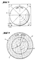
- the square field shown in FIG. 3 is divided into eight sectors.
- the positioning is carried out so that the engraving is arranged in half in the two sectors II and III.
- One half of the engraving is to the left of the twelve o'clock position, and the other half of the engraving is to the right of the twelve o'clock position, with both engraving halves being the same Be clear of the twelve o'clock position. So that the test object 6 is correctly positioned, the holding and transport device 8 can have an xy displacement device.
- the component 6 to be tested is formed from different zones or parts for which different quality standards are sufficient or are also required, it is advantageous to make a corresponding zone division on the captured image (FIG. 2) of the component 6 to be tested.
- Such a zone division is shown schematically for a contact lens in FIG. 4.
- An optical zone OZ of the contact lens is defined by an area which is covered by a radius r1. Radii r2 and r3 define a font zone to be hidden in the engraving angle range.
- a lenticular zone LZ is defined by a region between radii r1 and r4, and the edge R of the lens is defined by the radius r4.
- Different error limits can be set for the optical OZ and for the lenticular zone LZ, the error limit for the optical zone OZ being set lower than the error limit for the lenticular zone LZ.
- An edge error limit can also be set for the edge R; for example, the longitudinal and / or transverse dimensions must not be larger than 50 ⁇ m.
- the error limit can also be set even lower in the invention, for example at 20 ⁇ m. This also applies to the error limits in the optical area OZ and in the lenticular area LZ.
- the error limit (error threshold) is set.
- an error detection can be carried out for the contact lens edge R according to the principle shown in FIGS. 5 and 6.
- Different criteria can be taken into account here individually or as a whole.
- a criterion can be whether or not the radius at a certain edge differs from a mean radius Rm by a predetermined radius deviation ⁇ Rg / 2.
- it can be taken into account as a criterion whether or not all of these excessive radius deviations exceed a certain threshold.
- it can also be examined as a criterion whether the curve shape of the edge deviates strongly from a circular shape or not, as is shown, for example, between the two curve parts C1 and C2 or between the curve parts C3 and C4 in FIG.
- 6 shows, for example, that there is a large radius deviation at approximately 150 °. In Fig. 5 this is shown with R1-R2. 6 also shows the strong deviation of the edge from the circular shape between the curve parts C3 and C4. Furthermore, a large radius deviation in the range of approximately 260 ° to 300 ° can be seen from FIG. 6.
- the errors mentioned can be recorded in the image analysis device 9 (FIG. 1) with the aid of a memory device 21 (FIG. 11), in which the zone division shown in FIG. 4 is defined, in cooperation with limit value memories.
- a limit value memory 27 for the optical zone OZ there is a limit value memory 27 for the optical zone OZ, a limit value memory 28 for the lenticular zone LZ and a third limit value memory 29 for the R and R intended.
- Assigned pixel counters 23 are provided for the corresponding zones.
- the pixel counters which indicate values for the error quantities in the respective zones, deliver these values to comparators 24, 25 and 26, which are connected to the assigned limit value memories 27, 28 and 29 described.
- the comparison result can be stored in a buffer 30 for the respective zones and, if necessary, can be displayed on a monitor together with the captured image in the image capture memory 20.
- Solution memory 20 are displayed on a monitor.
- the comparators 24, 25 and 26 are controlled either via the buffer store 30 or directly via a sorting device 11 (FIG. 1).
- This sorter 11 is connected to the holding and transport device 8 or in operative connection. This is shown schematically by a dashed line in FIG. 1.
- the component 6 to be tested is then left in dependence on the holding and transport device 8 if it meets the quality requirements in accordance with the comparison result.
- the component 6 to be tested is then transferred to the next processing station. If the component 6 does not meet the quality requirements, it is removed from the holding and transport device 8 by the action of the sorting device 11.
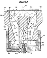
- FIG. 12 An exemplary embodiment of the device for illuminating the test object, for example illuminating the contact lens, is shown in FIG. 12.
- 110 denotes a central first reflector body.
- the first reflector body 110 has a flat, upper end face 112.
- the upper end face 112 extends perpendicular to a system axis 114.
- the reflector body 110 forms a convex-conical, first reflector 118.
- the cone axis of the reflector 118 coincides with the system axis 114.
- a light source 120 is arranged on the system axis 114 below the reflector body 110.
- a central light bundle 122 falls from the light source 120 onto the convex-conical, first reflector 118.
- the light bundle 122 is radially fanned out by the first reflector 118.
- the marginal rays 124 and the central ray 126 of the light bundle 122 running along the system axis 114 are shown before and after the reflection on the first reflector 118.
- the radially fanned light bundle 122 falls on a second reflector 128.
- the second reflector 128 is concave-cylindrical and coaxial to the system axis 114.
- the second reflector 128 is attached to a second reflector body 130.
- the second reflector body has an annular, flat end face 132.
- the cylindrical reflector 128 is connected on the inside to the end face 132.
- the reflector body 130 adjoining the end face 132, has a cylindrical outer surface 134 coaxial with the reflector 128. Adjoining the cylindrical outer surface 134, the reflector body 130 forms a conical section 136.
- a cylindrical section 138 which is provided with an external thread, adjoins the conical section 136.
- a conical section 140 adjoins the cylindrical reflector 128 on the inside.
- the reflector body 130 forms a lower end face 142 with a central opening 144.
- the light source 120 projects through this opening 144 into the interior of the reflector body 130.
- the concave-cylindrical second reflector 128 reflects the radially fanned light bundle 122 in such a way that it is collected in a light spot in an almost grazing manner in the center of the support 148.
- the second reflector body 130 is screwed with the section 138 provided with an external thread into a cup-shaped housing part 156 provided with an internal thread 154.
- the housing part 156 carries a base 158 for the light source 120 on the inside of the system axis 114.
- support rods 160 are held in the bottom of the pot-shaped housing part 156 and carry the first reflector body 110.
- the support rods 160 are guided through aligned openings in the bottom of the housing part 156 and through a transverse bore 162 of clamping screws 164.
- the clamping screws 164 are seated in radial threaded bores 166 in the bottom of the housing part 156 between the aligned openings.
- the clamping screws 164 can be loosened.
- the support rods 160 and thus the first reflector body 110 can be adjusted in height relative to the cup-shaped housing part 156. It is thus possible to adjust the reflector body 110 relative to the light source 120.
- the housing part 156, the light source 120 and the first reflector body 110 form a cohesive assembly 170, which as a whole extends over the internal thread 154 and the externally threaded section 138 of the second Reflector body 130 is adjustable relative to the second reflector body 130 and thus to the second reflector 128 and the support 148 in the direction of the system axis 114 (or vice versa).
- the light spot generated in the support plane is adapted to the dimensions of the test objects. Furthermore, the device can be set so that there is optimal contrast for error detection.
- the reflectors 118 and 128 can be designed to be specular.
- the surfaces of the first and second reflectors 118 and 128 can, however, also be designed to be partially diffusely reflective.
- the light source is a PTC thermistor ring light.
- the adjustability of the lighting geometry can then consist in that the radiation characteristic of the PTC thermistor ring light can be adapted to the geometry of the test object.
- FIGS. 7 and 8 two different manufacturing methods for contact lenses will now be used to demonstrate how the image analysis according to the invention can be integrated into the manufacturing process at different manufacturing stages or steps in combination with other image processing methods, so that an automatic sequence of the entire manufacturing of the contact lens is achieved becomes.
- FIG. 7 shows a so-called full mold process, which includes molding the contact lens, in its individual steps with an integrated automatic check using the image analysis according to the invention.
- Full mold processes are known (e.g. EP 0 367 513 and Wo 87/04390).
- a manufacturing step 31 the mold inserts (optical tools), which consist of high-quality metals / alloys, are manufactured, for example, by machining.
- a first test step 32 can already be carried out here with the aid of an image analysis. This test step can check the surface quality of the mold inserts and the geometry of the mold inserts. The mold inserts are then inserted into an injection mold in a step 33.
- an optical test can be carried out with the aid of an image analysis in a test step 35 to check the surface quality and the installation dimensions.
- test step 36 with image analysis can be integrated, so that the surface quality, the geometry (distortion and the like) as well as the absence of dust of the mold halves produced can be checked.
- a test step 38 can also be integrated here, in which the correct closing and the presence of air bubbles can be determined with the aid of the illustrated image analysis.
- the contact lens material which is enclosed by the two mold halves, is then polymerized in a step 39.
- a test step 40 with a closed mold that is translucent not only the course of the polymerization but also the polymerization shrinkage of the polymerized material and a suitable adjustment of the two mold halves can be monitored in this context. If necessary, the adjustment of the two mold halves can be controlled to compensate for the polymerization shrinkage, depending on the result of the image analysis and the polymerisation shrinkage detected.
- the two mold halves are opened.
- an intermediate check can be carried out here with regard to gross defects such as cracks, breakouts and the like on the lens body produced.
- the contact lens is removed from the mold and a dry test can be carried out on the contact lens with the aid of the image analysis explained in a test step 44. This can be followed in a manufacturing step 45 by the hydration of the lens body.
- the lens dry or hydrated
- the lens is introduced into glasses or into so-called foil packs 68, which are shown in FIGS. 9 and 10.
- test step 47 It can then be checked in a test step 47 whether the lens has been inserted into the storage container 69. This is done as part of a so-called attendance check. You can also monitor whether the liquid level in the storage container is correct. Furthermore, the cleanliness of the storage liquid and the lens itself can be monitored. Furthermore, lens quality and refractive power can be subjected to a final test. The tests explained in test step 47 can be carried out using the image analysis described above. The containers (FIGS. 9, 10) are then closed with the cover foils 71 by welding.
- a button is cut from a rod made of contact lens material in a production step 48 and inserted into a chuck of a lathe.
- Automatic lathes are known. For this purpose, reference is made, for example, to German Patent 31 10 624.
- the button can be checked with regard to material inclusions and its dimensions (trim dimensions) with the aid of the image analysis described above.
- an inner curve IK on the button is produced by turning using a turning tool in the automatic lathe.
- the rotation image and the surface quality and, if appropriate, also the geometry, for which a known moiree method can also be used can be checked by image analysis.
- the inner curve IK is polished. If necessary, the polishing image, the surface quality and again the geometry of the inner curve can be checked in a test step 53.
- the button is then cemented onto a spindle of the automatic lathe in a production step 54.
- the button with its inner curve is cemented onto the spindle.
- the quality and dimensions of the wax layer, which is used for cementing, as well as the concentricity and a vertex determination can be carried out in a test step 55 with the aid of an optical image analysis.
- the outer curve AK is then rotated in a production step 56.
- the rotation image, the geometry and the center thickness of the finished lens can be checked in a test step 57.
- the outer curve AK is then polished in a production step 58.
- the polishing pattern, the geometry and the center thickness of the contact lens can then be checked in a test step 59.
- test step 57 can also be omitted.
- a manufacturing step 60 the contact lens is cemented off the dome of the automatic lathe.
- the edge processing of the contact lens takes place in a production step 61.
- the contact lens is cleaned in a subsequent production step 62.
- the cleaning of the contact lens can be followed by a test step 63, in which a dry test of the contact lens is carried out with the aid of the image analysis (eg FIG. 1).
- the engraving of the contact lens as production step 64.
- the engraving for example shown in FIGS. 3 and 4, is then embossed into the contact lens body.
- a surface treatment of the contact lens as manufacturing step 65.
- This has the particular advantage that the surface of the lens is made wettable by the tear fluid.
- the wettability test can then also be carried out using image analysis (e.g. Fig. 1). The image analysis can determine whether droplets are formed on the surface or whether the surface of the lens is wetted by the liquid.
- the lens is inserted, for example, in foil packs (FIGS. 9, 10). This can then be followed, as in the full mold process shown in FIG. 7, by a test step which corresponds to test step 47.
- the cover foils are then welded onto the containers.
Landscapes
- Physics & Mathematics (AREA)
- General Physics & Mathematics (AREA)
- Chemical & Material Sciences (AREA)
- Analytical Chemistry (AREA)
- Biochemistry (AREA)
- Pathology (AREA)
- Health & Medical Sciences (AREA)
- Life Sciences & Earth Sciences (AREA)
- Spectroscopy & Molecular Physics (AREA)
- General Health & Medical Sciences (AREA)
- Immunology (AREA)
- Geometry (AREA)
- Investigating Materials By The Use Of Optical Means Adapted For Particular Applications (AREA)
- Testing Of Optical Devices Or Fibers (AREA)
- Eye Examination Apparatus (AREA)
- Eyeglasses (AREA)
- Image Processing (AREA)
- Image Analysis (AREA)
Claims (20)
- Procédé de contrôle de composants optiques transparents, procédé suivant lequel la représentation de l'image suivie de l'analyse de l'image permettent de détecter des défauts sur le composant dont l'image a été reproduite, caractérisé en ce que la représentation de l'image du composant est effectuée par un éclairage sur fond sombre adapté au composant de manière qu'une image en contraste du composant sous forme d'éléments de surface soit générée, en ce que, le composant étant ainsi éclairé, une image de l'ensemble du composant est reproduite en un unique instant et la surface de l'image des défauts rendus ainsi visibles est déterminée et comparée à une ou plusieurs valeurs de seuil.
- Procédé selon la revendication 1, caractérisé en ce que l'image du composant est reproduite par un détecteur d'image à CCD.
- Procédé selon la revendication 1 ou 2, caractérisé en ce que la surface de l'image de chaque défaut détecté est subdivisée en pixels et les pixels sont comptés et en ce que le nombre déterminé de pixels est comparé à un nombre prédéterminé de pixels.
- Procédé selon l'une des revendications 1 à 3, caractérisé en ce que la détection des défauts est effectuée au cours d'une ou de plusieurs étapes de fabrication lors de la réalisation du composant.
- Procédé selon l'une des revendications 1 à 4, caractérisé en ce que la détection de défauts est effectuée lors de la réalisation de composants ophtalmologiques.
- Procédé selon l'une des revendications 1 à 5, caractérisé en ce que des seuils différents servant de normes de qualité sont fixés pour des zones différentes du composant à contrôler.
- Procédé selon l'une des revendications 1 à 6, caractérisé en ce que, lors du contrôle d'une lentille de contact, des seuils différents servant de normes de qualité sont fixés pour la zone optique, la zone lenticulaire et le bord de la lentille.
- Dispositif de contrôle de composants optiques transparents au moyen d'un dispositif optique de génération d'image, qui comprend un dispositif d'éclairage pour l'éclairage du composant, ainsi qu'un dispositif (2) de traitement de l'image qui comprend un dispositif (3) de prise de vue, caractérisé en ce que le dispositif d'éclairage (1) est constitué d'un dispositif d'éclairage sur fond obscur qui comprend une source lumineuse (120) et une optique d'éclairage sur fond obscur (118, 128), dont la géométrie est réglable pour l'adaptation au composant, de manière qu'une image en contraste du composant soit générée et en ce que le dispositif (3) de prise de vue comprend un détecteur d'image (4) qui prend une image de l'ensemble du composant en un unique instant pour la détermination de la surface de chaque défaut détecté dans l'image en contraste et pour la comparaison des surfaces des défauts à une ou plusieurs valeurs de seuil.
- Dispositif selon la revendication 8, caractérisé en ce que le détecteur d'image (4) est constitué d'un CCD.
- Dispositif selon la revendication 8 ou 9, caractérisé en ce qu'un dispositif de lecture (7) destiné à la lecture en pixels des surfaces reproduites des défauts est connecté au détecteur d'image (4).
- Dispositif selon l'une des revendication 8 à 10, caractérisé en ce que le dispositif (2) de traitement de l'image comprend un comparateur (24, 25, 26) qui est connecté à un dispositif de détermination de surface (20, 21, 23) et à un dispositif de mémorisation de seuils (27, 28, 29).
- Dispositif selon l'une des revendication 8 à 11, caractérisé en ce que les seuils sont des grandeurs prescrites de surface.
- Dispositif selon l'une des revendication 8 à 12, caractérisé en ce que(a) un premier corps réflecteur (110) est prévu sous un support (148) comprenant une surface d'appui pour le composant à contrôler,(b) le premier corps réflecteur (110) comprend une surface extrême (112) qui est sensiblement parallèle au plan d'appui du support (148) et qui forme un fond d'objet pour le composant,(c) le premier corps réflecteur (110) comprend par ailleurs un premier miroir réflecteur convexe-conique (118) qui est tourné à l'opposé de ladite surface extrême (112) et dont l'axe du cône coïncide avec un axe du système (114) qui est perpendiculaire à la surface extrême (112),(d) la source lumineuse (120) est disposée sur l'axe du système (114) et(e) un second corps réflecteur (130) comprenant un miroir réflecteur annulaire concave (108) est disposé coaxialement à l'axe du système (114).
- Dispositif selon la revendication 13, caractérisé en ce que le miroir réflecteur annulaire concave (128) est cylindrique.
- Dispositif selon la revendication 13 ou 14, caractérisé en ce que la source lumineuse (120) est réunie avec le premier miroir réflecteur (118) en un module (170) dont la position est réglable le long de l'axe du système (114) par rapport au second corps réflecteur (130) et au support (148).
- Dispositif selon l'une des revendications 13 à 15, caractérisé en ce que la source lumineuse est une lumière annulaire d'une thermistance PTC.
- Dispositif selon la revendication 16, caractérisé en ce que la caractéristique de radiation de la lumière annulaire de la thermistance PTC est adaptable à la géométrie du composant.
- Dispositif selon l'une des revendications 13 à 17, caractérisé en ce qu'une plaque (146) comportant sur les deux côtés une couche anti-réflexion est prévue en support (148) pour le composant.
- Dispositif selon l'une des revendications 13 à 15, caractérisé en ce que le premier (118) et le second (120) miroirs réflecteurs sont spéculaires.
- Dispositif selon l'une des revendications 13 à 15, caractérisé en ce que les surfaces du premier (118) et du second (120) miroirs réflecteurs sont réfléchissantes de manière partiellement diffuse.
Applications Claiming Priority (4)
| Application Number | Priority Date | Filing Date | Title |
|---|---|---|---|
| CH403290 | 1990-12-19 | ||
| CH4032/90 | 1990-12-19 | ||
| DE19914124003 DE4124003C2 (de) | 1991-07-19 | 1991-07-19 | Beleuchtungseinrichtung zum Beleuchten von klar-transparenten Prüfobjekten, für die Untersuchung der Prüfobjekte auf Fehler |
| DE4124003 | 1991-07-19 |
Publications (2)
| Publication Number | Publication Date |
|---|---|
| EP0491663A1 EP0491663A1 (fr) | 1992-06-24 |
| EP0491663B1 true EP0491663B1 (fr) | 1996-01-10 |
Family
ID=25694472
Family Applications (1)
| Application Number | Title | Priority Date | Filing Date |
|---|---|---|---|
| EP19910810978 Expired - Lifetime EP0491663B1 (fr) | 1990-12-19 | 1991-12-13 | Procédé et dispositif pour l'inspection d'éléments optiques, notamment d'éléments ophtalmiques, et appareil pour l'illumination d'objets transparents à examiner |
Country Status (13)
| Country | Link |
|---|---|
| EP (1) | EP0491663B1 (fr) |
| JP (1) | JPH04321186A (fr) |
| KR (1) | KR100202215B1 (fr) |
| AT (1) | ATE132971T1 (fr) |
| AU (1) | AU649291B2 (fr) |
| CA (1) | CA2057832A1 (fr) |
| DE (1) | DE59107249D1 (fr) |
| DK (1) | DK0491663T3 (fr) |
| ES (1) | ES2082178T3 (fr) |
| GR (1) | GR3018639T3 (fr) |
| HK (1) | HK1003125A1 (fr) |
| IE (1) | IE70436B1 (fr) |
| PT (1) | PT99855B (fr) |
Cited By (4)
| Publication number | Priority date | Publication date | Assignee | Title |
|---|---|---|---|---|
| US6259518B1 (en) | 1999-08-10 | 2001-07-10 | Novartis Ag | Wetcell device for inspection |
| US6765661B2 (en) | 2001-03-09 | 2004-07-20 | Novartis Ag | Lens inspection |
| CN100465625C (zh) * | 2005-10-21 | 2009-03-04 | 京元电子股份有限公司 | 晶片影像检视方法及系统 |
| CN101793595B (zh) * | 2002-02-21 | 2012-05-16 | 庄臣及庄臣视力保护公司 | 用于检查光学设备的装置 |
Families Citing this family (46)
| Publication number | Priority date | Publication date | Assignee | Title |
|---|---|---|---|---|
| US5412203A (en) * | 1991-07-15 | 1995-05-02 | Fuji Electric Co., Ltd. | Cylindrical container inner surface tester |
| JP3044951B2 (ja) * | 1992-11-25 | 2000-05-22 | 富士電機株式会社 | 円形容器内面検査装置 |
| IL107603A (en) * | 1992-12-21 | 1997-01-10 | Johnson & Johnson Vision Prod | Ophthalmic lens inspection method and apparatus |
| GR1002574B (el) * | 1992-12-21 | 1997-02-06 | Johnson & Johnson Vision Products Inc. | Παλλετα για την υποδοχη και μεταφορα δοχειων οφθαλμικων φακων. |
| NZ250042A (en) * | 1992-12-21 | 1997-01-29 | Johnson & Johnson Vision Prod | Robotic inspection of ophthalmic lenses |
| IL107601A (en) * | 1992-12-21 | 1997-09-30 | Johnson & Johnson Vision Prod | Illumination and imaging subsystems for a lens inspection system |
| IL107602A0 (en) * | 1992-12-21 | 1994-02-27 | Johnson & Johnson Vision Prod | Method of inspecting ophthalmic lenses |
| NZ250453A (en) * | 1992-12-21 | 1996-12-20 | Johnson & Johnson Vision Prod | Ophthalmic lens package; planar surface with concave bowl for containing lens, sealing sheet covering bowl with lens therein |
| GR1002789B (el) * | 1992-12-21 | 1997-10-17 | Johnson & Johnson Vision Products Inc. | Μια συσκευη για την μεταφορα οφθαλμικων φακων. |
| GR1002072B (en) * | 1992-12-21 | 1995-11-30 | Johnson & Johnson Vision Prod | Illumination system for opthalmic lens inspection. |
| IL107605A (en) * | 1992-12-21 | 1998-01-04 | Johnson & Johnson Vision Prod | Lens inspection system |
| IL107513A (en) * | 1992-12-21 | 1997-07-13 | Johnson & Johnson Vision Prod | Ophthalmic lens inspection system and method |
| TW325744U (en) * | 1993-07-21 | 1998-01-21 | Ciba Geigy Ag | Two-sided contact lens mold |
| DE69416680T2 (de) | 1993-07-29 | 1999-06-24 | Wesley-Jessen Corp., Des Plaines, Ill. | Vorrichtung zur untersuchung von optischen elementen |
| JP3734512B2 (ja) * | 1993-12-27 | 2006-01-11 | 株式会社メニコン | コンタクトレンズ外観検査方法および外観検査装置 |
| US5500732A (en) * | 1994-06-10 | 1996-03-19 | Johnson & Johnson Vision Products, Inc. | Lens inspection system and method |
| IL113945A0 (en) * | 1994-06-10 | 1995-08-31 | Johnson & Johnson Vision Prod | System and method for inspecting lenses |
| US5633504A (en) * | 1995-03-30 | 1997-05-27 | Wesley-Jessen Corporation | Inspection of optical components |
| AU698522B2 (en) * | 1995-09-29 | 1998-10-29 | Johnson & Johnson Vision Products, Inc. | Lens parameter measurement using optical sectioning |
| US5818573A (en) * | 1997-02-06 | 1998-10-06 | Pbh, Inc. | Opthalmic lens inspection system |
| US5801822A (en) * | 1997-02-06 | 1998-09-01 | Pbh, Inc. | Ophthalmic lens inspection system |
| US6047082A (en) * | 1997-11-14 | 2000-04-04 | Wesley Jessen Corporation | Automatic lens inspection system |
| US6201600B1 (en) * | 1997-12-19 | 2001-03-13 | Northrop Grumman Corporation | Method and apparatus for the automatic inspection of optically transmissive objects having a lens portion |
| EP1105707B1 (fr) * | 1998-08-17 | 2009-06-03 | Novartis AG | Module d'essai pour controler la presence eventuelle de defauts sur des pieces optiques |
| IL126809A (en) * | 1998-10-29 | 2001-08-26 | Sarin Technologies Ltd | Apparatus and method of examining the shape of gemstones |
| US6246062B1 (en) | 1998-11-05 | 2001-06-12 | Johnson & Johnson Vision Care, Inc. | Missing lens detection system and method |
| SG87848A1 (en) | 1998-11-05 | 2002-04-16 | Johnson & Johnson Vision Prod | Missing lens detection system and method |
| DE29901791U1 (de) * | 1999-02-02 | 2000-07-06 | Novartis Ag, Basel | Linsenmesseinrichtung |
| DE60130057T2 (de) * | 2000-05-01 | 2008-05-15 | Fujifilm Corp. | Vorrichtung zur Abgabe eines Fluids |
| JP4426080B2 (ja) * | 2000-10-11 | 2010-03-03 | 株式会社メニコン | 眼用レンズの汚れ検出方法及び装置 |
| ATE545018T1 (de) | 2000-10-23 | 2012-02-15 | Novartis Ag | Ultraschallvorrichtung zur inspektion von ophthalmischen linsen |
| EP1203952B1 (fr) * | 2000-10-23 | 2012-02-08 | Novartis AG | Dispositif ultrasonore destiné à l'inspection de lentilles ophtalmiques |
| US6577387B2 (en) | 2000-12-29 | 2003-06-10 | Johnson & Johnson Vision Care, Inc. | Inspection of ophthalmic lenses using absorption |
| JP2003042737A (ja) * | 2001-07-26 | 2003-02-13 | Toray Ind Inc | 切削加工品の検査方法 |
| WO2003087755A1 (fr) * | 2002-04-12 | 2003-10-23 | Menicon Co., Ltd. | Systeme et procede d'assistance destine a des lentilles de contact |
| US7416300B2 (en) * | 2006-05-25 | 2008-08-26 | Coopervision International Holding Company, Lp | Measurement of lenses and lens molds using optical coherence tomography |
| CN101650258B (zh) * | 2008-08-14 | 2012-03-14 | 鸿富锦精密工业(深圳)有限公司 | 镜头模组检测装置 |
| SG195400A1 (en) | 2012-05-10 | 2013-12-30 | Menicon Singapore Pte Ltd | Systems and methods for the inspection of contact lenses |
| KR101334168B1 (ko) * | 2012-09-19 | 2013-11-29 | 주식회사 케이피씨 | 엘이디 무영등의 복합 측정시험장치 |
| GB2560951B (en) | 2017-03-29 | 2020-06-17 | Redlux Ltd | Inspection of components for imperfections |
| CN110646169B (zh) * | 2019-10-28 | 2022-03-08 | 沈阳仪表科学研究院有限公司 | 曲面光学薄膜元件反射率测量方法 |
| MX2024003074A (es) | 2021-09-16 | 2024-03-27 | Schneider Gmbh & Co Kg | Procedimiento y aparato para el control de calidad de lentes oftalmicas. |
| CN114486939B (zh) * | 2022-04-08 | 2022-07-22 | 欧普康视科技股份有限公司 | 一种镜片划痕检测系统及方法 |
| CN116990450B (zh) * | 2023-07-18 | 2024-04-26 | 欧几里德(苏州)医疗科技有限公司 | 一种角膜塑形镜的缺陷检测方法及系统 |
| CN118275443B (zh) * | 2024-04-02 | 2025-03-25 | 平方和(北京)科技有限公司 | 一种隐形眼镜缺陷检测方法及系统 |
| CN118558618B (zh) * | 2024-04-17 | 2025-09-30 | 平方和(北京)科技有限公司 | 隐形眼镜三维形貌测量方法、装置及隐形眼镜缺陷检测系统 |
Family Cites Families (12)
| Publication number | Priority date | Publication date | Assignee | Title |
|---|---|---|---|---|
| US3988068A (en) * | 1974-05-09 | 1976-10-26 | Itek Corporation | Method and apparatus for detecting cosmetic defects in opthalmic lenses |
| DD138110A1 (de) * | 1978-07-27 | 1979-10-10 | Horst Riesenberg | Auflicht-beleuchtungseinrichtung fuer mikroskope |
| DD145805B1 (de) * | 1979-08-27 | 1982-06-30 | Johannes Grosser | Beleuchtungsanordnung fuer mikroskope |
| DE3115634A1 (de) * | 1981-04-18 | 1982-11-04 | Feldmühle AG, 4000 Düsseldorf | Verfahren und vorrichtung zum pruefen von durch kreislinien begrenzten flaechen |
| DE3475566D1 (en) * | 1984-05-14 | 1989-01-12 | Ibm Deutschland | Method and device for the inspection of surfaces |
| US4733360A (en) * | 1984-06-14 | 1988-03-22 | Dai Nippon Insatsu Kabushiki Kaisha | Device and method for inspecting card-like articles |
| DE3432002A1 (de) * | 1984-08-31 | 1986-03-06 | Fa. Carl Zeiss, 7920 Heidenheim | Verfahren und vorrichtung zur optischen untersuchung von kontaktlinsen |
| GB2171812B (en) * | 1984-11-20 | 1988-08-17 | Michael Roy Killpartrick | Wet cell inspection of contact lenses |
| AU580642B2 (en) * | 1984-11-29 | 1989-01-19 | Unisearch Limited | Lens zonometer |
| DE3620129A1 (de) * | 1986-06-14 | 1987-12-17 | Zeiss Carl Fa | Vorrichtung zum pruefen von bauteilen aus transparentem material auf oberflaechenfehler und einschluesse |
| US4943713A (en) * | 1987-11-27 | 1990-07-24 | Hajime Industries Ltd. | Bottle bottom inspection apparatus |
| JPH02257007A (ja) * | 1989-03-30 | 1990-10-17 | Seiko Epson Corp | コンタクトレンズ外周欠け検査装置 |
-
1991
- 1991-12-04 AU AU88816/91A patent/AU649291B2/en not_active Ceased
- 1991-12-13 EP EP19910810978 patent/EP0491663B1/fr not_active Expired - Lifetime
- 1991-12-13 ES ES91810978T patent/ES2082178T3/es not_active Expired - Lifetime
- 1991-12-13 AT AT91810978T patent/ATE132971T1/de not_active IP Right Cessation
- 1991-12-13 DK DK91810978T patent/DK0491663T3/da active
- 1991-12-13 DE DE59107249T patent/DE59107249D1/de not_active Expired - Lifetime
- 1991-12-17 CA CA 2057832 patent/CA2057832A1/fr not_active Abandoned
- 1991-12-18 IE IE441191A patent/IE70436B1/en not_active IP Right Cessation
- 1991-12-18 KR KR1019910023286A patent/KR100202215B1/ko not_active Expired - Fee Related
- 1991-12-18 PT PT99855A patent/PT99855B/pt not_active IP Right Cessation
- 1991-12-19 JP JP3354617A patent/JPH04321186A/ja active Pending
-
1996
- 1996-01-11 GR GR950403654T patent/GR3018639T3/el unknown
-
1998
- 1998-03-16 HK HK98102154A patent/HK1003125A1/xx not_active IP Right Cessation
Cited By (4)
| Publication number | Priority date | Publication date | Assignee | Title |
|---|---|---|---|---|
| US6259518B1 (en) | 1999-08-10 | 2001-07-10 | Novartis Ag | Wetcell device for inspection |
| US6765661B2 (en) | 2001-03-09 | 2004-07-20 | Novartis Ag | Lens inspection |
| CN101793595B (zh) * | 2002-02-21 | 2012-05-16 | 庄臣及庄臣视力保护公司 | 用于检查光学设备的装置 |
| CN100465625C (zh) * | 2005-10-21 | 2009-03-04 | 京元电子股份有限公司 | 晶片影像检视方法及系统 |
Also Published As
| Publication number | Publication date |
|---|---|
| PT99855A (pt) | 1994-01-31 |
| AU8881691A (en) | 1992-06-25 |
| IE914411A1 (en) | 1992-07-01 |
| EP0491663A1 (fr) | 1992-06-24 |
| IE70436B1 (en) | 1996-11-27 |
| JPH04321186A (ja) | 1992-11-11 |
| HK1003125A1 (en) | 1998-10-09 |
| ATE132971T1 (de) | 1996-01-15 |
| CA2057832A1 (fr) | 1992-06-20 |
| GR3018639T3 (en) | 1996-04-30 |
| PT99855B (pt) | 1999-02-26 |
| KR920012892A (ko) | 1992-07-28 |
| DK0491663T3 (da) | 1996-02-05 |
| DE59107249D1 (de) | 1996-02-22 |
| ES2082178T3 (es) | 1996-03-16 |
| KR100202215B1 (ko) | 1999-06-15 |
| AU649291B2 (en) | 1994-05-19 |
Similar Documents
| Publication | Publication Date | Title |
|---|---|---|
| EP0491663B1 (fr) | Procédé et dispositif pour l'inspection d'éléments optiques, notamment d'éléments ophtalmiques, et appareil pour l'illumination d'objets transparents à examiner | |
| DE69428381T2 (de) | System zur Inspection von optischen Bauelementen | |
| DE69320020T3 (de) | Verfahren und System zur Inspektion von ophthalmischen Linsen | |
| DE69525195T2 (de) | Optische Inspektion von Dimensionsparametern von Behältern | |
| DE102010032410B4 (de) | Inspektionsvorrichtung, Fertigungsanlage mit Inspektionsvorrichtung und Inspektionsverfahren für Gefäße | |
| DE69028331T2 (de) | Überprüfung der Endbearbeitung von Flaschenhälsen | |
| HK1003125B (en) | Procedure and apparatus for the examination of optical components, particularly ophthalmic components, and device for the illuminiation of transparent objects under examination | |
| DE69317103T3 (de) | Beleuchtungssystem zur Inspektion von Kontaktlinsen | |
| US6314199B1 (en) | Process and apparatus for examining optical components, especially optical components for the eye and device for illuminating clear-transparent | |
| EP0249799B1 (fr) | Appareil pour inspecter des éléments en matériau transparent pour la détection de défauts de surface et d'inclusions | |
| DE102014217771B4 (de) | Vorrichtung und Verfahren zur Qualitätskontrolle transparenter Objekte | |
| DE112015002287T5 (de) | System und Verfahren zum Inspizieren ophthalmischer Linsen | |
| DE19739250C2 (de) | Optische Erfassung von Freiformflächen | |
| DE4224640C2 (de) | Gerät für die automatische Messung von Form und Profil der Innenkontur eines Brillenfassungsrahmens | |
| DE19538013A1 (de) | Glasbehälterprüfmaschine | |
| EP1920213B8 (fr) | Dispositif de controle automatique pour endoprotheses vasculaires et procede de controle automatique | |
| DE3044611A1 (de) | Verfahren und vorrichtung zur erkennung von querschnittsprofilen von objekten | |
| EP1826556A2 (fr) | Dispositif de vérification | |
| DE102018222231A1 (de) | Vorrichtung und Verfahren zur optischen Vermessung einer Innenkontur einer Brillenfassung | |
| DE102005013755B4 (de) | Verfahren zur Herstellung von Systemen zusammengesetzter Linsen | |
| DE102023209323A1 (de) | System und verfahren zur prüfung von formungsfehlern in feuchten ophthalmischen linsen | |
| DE4434475A1 (de) | Verfahren und Vorrichtung zur Qualitätskontrolle eines Gegenstandes | |
| WO2008113638A2 (fr) | Dispositif et procédé pour l'inspection de défauts en bordure d'une plaquette, et utilisation du dispositif dans un système d'inspection pour plaquettes | |
| DE19542630C2 (de) | Vorrichtung und Verfahren zum Prüfen von Gefäßwänden | |
| DE102006008552A1 (de) | Prüfeinrichtung |
Legal Events
| Date | Code | Title | Description |
|---|---|---|---|
| PUAI | Public reference made under article 153(3) epc to a published international application that has entered the european phase |
Free format text: ORIGINAL CODE: 0009012 |
|
| 17P | Request for examination filed |
Effective date: 19911218 |
|
| AK | Designated contracting states |
Kind code of ref document: A1 Designated state(s): AT BE CH DE DK ES FR GB GR IT LI LU MC NL SE |
|
| RBV | Designated contracting states (corrected) |
Designated state(s): AT BE CH DE DK ES FR GB GR IT LI LU NL SE |
|
| 17Q | First examination report despatched |
Effective date: 19940616 |
|
| GRAA | (expected) grant |
Free format text: ORIGINAL CODE: 0009210 |
|
| AK | Designated contracting states |
Kind code of ref document: B1 Designated state(s): AT BE CH DE DK ES FR GB GR IT LI LU NL SE |
|
| REF | Corresponds to: |
Ref document number: 132971 Country of ref document: AT Date of ref document: 19960115 Kind code of ref document: T |
|
| REG | Reference to a national code |
Ref country code: DK Ref legal event code: T3 |
|
| REF | Corresponds to: |
Ref document number: 59107249 Country of ref document: DE Date of ref document: 19960222 |
|
| ITF | It: translation for a ep patent filed | ||
| REG | Reference to a national code |
Ref country code: CH Ref legal event code: NV Representative=s name: CIBA-GEIGY AG PATENTABTEILUNG |
|
| REG | Reference to a national code |
Ref country code: ES Ref legal event code: FG2A Ref document number: 2082178 Country of ref document: ES Kind code of ref document: T3 |
|
| ET | Fr: translation filed | ||
| REG | Reference to a national code |
Ref country code: GR Ref legal event code: FG4A Free format text: 3018639 |
|
| GBT | Gb: translation of ep patent filed (gb section 77(6)(a)/1977) |
Effective date: 19960327 |
|
| PLBE | No opposition filed within time limit |
Free format text: ORIGINAL CODE: 0009261 |
|
| STAA | Information on the status of an ep patent application or granted ep patent |
Free format text: STATUS: NO OPPOSITION FILED WITHIN TIME LIMIT |
|
| 26N | No opposition filed | ||
| REG | Reference to a national code |
Ref country code: CH Ref legal event code: PFA Free format text: CIBA-GEIGY AG;BODENSEEWERK GERAETETECHNIK GMBH TRANSFER- BODENSEEWERK GERAETETECHNIK GMBH;NOVARTIS AG |
|
| REG | Reference to a national code |
Ref country code: CH Ref legal event code: NV Representative=s name: NOVARTIS AG |
|
| NLS | Nl: assignments of ep-patents |
Owner name: NOVARTIS AG;BODENSEEWERK GERAETETECHNIK GMBH |
|
| REG | Reference to a national code |
Ref country code: ES Ref legal event code: PC2A |
|
| REG | Reference to a national code |
Ref country code: FR Ref legal event code: TP |
|
| PGFP | Annual fee paid to national office [announced via postgrant information from national office to epo] |
Ref country code: AT Payment date: 20001009 Year of fee payment: 10 |
|
| PGFP | Annual fee paid to national office [announced via postgrant information from national office to epo] |
Ref country code: BE Payment date: 20001012 Year of fee payment: 10 |
|
| PGFP | Annual fee paid to national office [announced via postgrant information from national office to epo] |
Ref country code: NL Payment date: 20001016 Year of fee payment: 10 Ref country code: SE Payment date: 20001016 Year of fee payment: 10 |
|
| PGFP | Annual fee paid to national office [announced via postgrant information from national office to epo] |
Ref country code: CH Payment date: 20001017 Year of fee payment: 10 Ref country code: DK Payment date: 20001017 Year of fee payment: 10 |
|
| PGFP | Annual fee paid to national office [announced via postgrant information from national office to epo] |
Ref country code: GR Payment date: 20001020 Year of fee payment: 10 |
|
| PGFP | Annual fee paid to national office [announced via postgrant information from national office to epo] |
Ref country code: LU Payment date: 20001023 Year of fee payment: 10 |
|
| PGFP | Annual fee paid to national office [announced via postgrant information from national office to epo] |
Ref country code: ES Payment date: 20001205 Year of fee payment: 10 |
|
| PG25 | Lapsed in a contracting state [announced via postgrant information from national office to epo] |
Ref country code: AT Free format text: LAPSE BECAUSE OF NON-PAYMENT OF DUE FEES Effective date: 20011213 Ref country code: DK Free format text: LAPSE BECAUSE OF NON-PAYMENT OF DUE FEES Effective date: 20011213 Ref country code: LU Free format text: LAPSE BECAUSE OF NON-PAYMENT OF DUE FEES Effective date: 20011213 |
|
| PG25 | Lapsed in a contracting state [announced via postgrant information from national office to epo] |
Ref country code: SE Free format text: LAPSE BECAUSE OF NON-PAYMENT OF DUE FEES Effective date: 20011214 |
|
| PG25 | Lapsed in a contracting state [announced via postgrant information from national office to epo] |
Ref country code: CH Free format text: LAPSE BECAUSE OF NON-PAYMENT OF DUE FEES Effective date: 20011231 Ref country code: LI Free format text: LAPSE BECAUSE OF NON-PAYMENT OF DUE FEES Effective date: 20011231 Ref country code: BE Free format text: LAPSE BECAUSE OF NON-PAYMENT OF DUE FEES Effective date: 20011231 Ref country code: GR Free format text: LAPSE BECAUSE OF NON-PAYMENT OF DUE FEES Effective date: 20011231 |
|
| REG | Reference to a national code |
Ref country code: GB Ref legal event code: IF02 |
|
| BERE | Be: lapsed |
Owner name: BODENSEEWERK GERATETECHNIK G.M.B.H. Effective date: 20011231 Owner name: NOVARTIS A.G. Effective date: 20011231 |
|
| PG25 | Lapsed in a contracting state [announced via postgrant information from national office to epo] |
Ref country code: NL Free format text: LAPSE BECAUSE OF NON-PAYMENT OF DUE FEES Effective date: 20020701 |
|
| EUG | Se: european patent has lapsed |
Ref document number: 91810978.6 |
|
| REG | Reference to a national code |
Ref country code: CH Ref legal event code: PL |
|
| NLV4 | Nl: lapsed or anulled due to non-payment of the annual fee |
Effective date: 20020701 |
|
| REG | Reference to a national code |
Ref country code: DK Ref legal event code: EBP |
|
| PG25 | Lapsed in a contracting state [announced via postgrant information from national office to epo] |
Ref country code: ES Free format text: LAPSE BECAUSE OF NON-PAYMENT OF DUE FEES Effective date: 20021214 |
|
| REG | Reference to a national code |
Ref country code: ES Ref legal event code: FD2A Effective date: 20030113 |
|
| PGFP | Annual fee paid to national office [announced via postgrant information from national office to epo] |
Ref country code: FR Payment date: 20051014 Year of fee payment: 15 |
|
| PGFP | Annual fee paid to national office [announced via postgrant information from national office to epo] |
Ref country code: IT Payment date: 20061231 Year of fee payment: 16 |
|
| REG | Reference to a national code |
Ref country code: FR Ref legal event code: ST Effective date: 20070831 |
|
| PG25 | Lapsed in a contracting state [announced via postgrant information from national office to epo] |
Ref country code: FR Free format text: LAPSE BECAUSE OF NON-PAYMENT OF DUE FEES Effective date: 20070102 |
|
| PG25 | Lapsed in a contracting state [announced via postgrant information from national office to epo] |
Ref country code: IT Free format text: LAPSE BECAUSE OF NON-PAYMENT OF DUE FEES Effective date: 20071213 |
|
| PGFP | Annual fee paid to national office [announced via postgrant information from national office to epo] |
Ref country code: GB Payment date: 20101208 Year of fee payment: 20 |
|
| PGFP | Annual fee paid to national office [announced via postgrant information from national office to epo] |
Ref country code: DE Payment date: 20101208 Year of fee payment: 20 |
|
| REG | Reference to a national code |
Ref country code: DE Ref legal event code: R071 Ref document number: 59107249 Country of ref document: DE |
|
| REG | Reference to a national code |
Ref country code: DE Ref legal event code: R071 Ref document number: 59107249 Country of ref document: DE |
|
| REG | Reference to a national code |
Ref country code: GB Ref legal event code: PE20 Expiry date: 20111212 |
|
| PG25 | Lapsed in a contracting state [announced via postgrant information from national office to epo] |
Ref country code: GB Free format text: LAPSE BECAUSE OF EXPIRATION OF PROTECTION Effective date: 20111212 |
|
| PG25 | Lapsed in a contracting state [announced via postgrant information from national office to epo] |
Ref country code: DE Free format text: LAPSE BECAUSE OF EXPIRATION OF PROTECTION Effective date: 20111214 |