EP0489646B1 - Verfahren und Vorrichtung zum Positionieren von einer Deckelfolienbahn vor deren Versiegelung an einer Behältereinheit - Google Patents
Verfahren und Vorrichtung zum Positionieren von einer Deckelfolienbahn vor deren Versiegelung an einer Behältereinheit Download PDFInfo
- Publication number
- EP0489646B1 EP0489646B1 EP91403271A EP91403271A EP0489646B1 EP 0489646 B1 EP0489646 B1 EP 0489646B1 EP 91403271 A EP91403271 A EP 91403271A EP 91403271 A EP91403271 A EP 91403271A EP 0489646 B1 EP0489646 B1 EP 0489646B1
- Authority
- EP
- European Patent Office
- Prior art keywords
- strip
- tops
- receptacles
- pitch
- containers
- Prior art date
- Legal status (The legal status is an assumption and is not a legal conclusion. Google has not performed a legal analysis and makes no representation as to the accuracy of the status listed.)
- Expired - Lifetime
Links
- 238000007789 sealing Methods 0.000 title claims abstract description 18
- 238000000034 method Methods 0.000 title claims abstract description 11
- 239000011888 foil Substances 0.000 title abstract 6
- 230000007246 mechanism Effects 0.000 claims description 13
- 230000033228 biological regulation Effects 0.000 claims description 3
- 230000001105 regulatory effect Effects 0.000 claims description 2
- 238000006073 displacement reaction Methods 0.000 claims 1
- 238000003466 welding Methods 0.000 description 13
- 238000010438 heat treatment Methods 0.000 description 5
- 230000009471 action Effects 0.000 description 4
- 230000000694 effects Effects 0.000 description 4
- 230000006835 compression Effects 0.000 description 3
- 238000007906 compression Methods 0.000 description 3
- 239000000463 material Substances 0.000 description 3
- 239000004698 Polyethylene Substances 0.000 description 2
- XAGFODPZIPBFFR-UHFFFAOYSA-N aluminium Chemical compound [Al] XAGFODPZIPBFFR-UHFFFAOYSA-N 0.000 description 2
- 229910052782 aluminium Inorganic materials 0.000 description 2
- 239000002131 composite material Substances 0.000 description 2
- 229940082150 encore Drugs 0.000 description 2
- 230000001939 inductive effect Effects 0.000 description 2
- 230000002093 peripheral effect Effects 0.000 description 2
- 229920003023 plastic Polymers 0.000 description 2
- 239000004033 plastic Substances 0.000 description 2
- -1 polyethylene Polymers 0.000 description 2
- 229920000573 polyethylene Polymers 0.000 description 2
- 230000008569 process Effects 0.000 description 2
- 230000015572 biosynthetic process Effects 0.000 description 1
- 230000000903 blocking effect Effects 0.000 description 1
- 230000005484 gravity Effects 0.000 description 1
- 230000031700 light absorption Effects 0.000 description 1
- 230000004048 modification Effects 0.000 description 1
- 238000012986 modification Methods 0.000 description 1
- 230000003287 optical effect Effects 0.000 description 1
- 229920000728 polyester Polymers 0.000 description 1
- 238000003825 pressing Methods 0.000 description 1
- 230000009467 reduction Effects 0.000 description 1
- 230000001360 synchronised effect Effects 0.000 description 1
- 238000003856 thermoforming Methods 0.000 description 1
- 230000007704 transition Effects 0.000 description 1
- 238000011144 upstream manufacturing Methods 0.000 description 1
Images
Classifications
-
- B—PERFORMING OPERATIONS; TRANSPORTING
- B65—CONVEYING; PACKING; STORING; HANDLING THIN OR FILAMENTARY MATERIAL
- B65B—MACHINES, APPARATUS OR DEVICES FOR, OR METHODS OF, PACKAGING ARTICLES OR MATERIALS; UNPACKING
- B65B41/00—Supplying or feeding container-forming sheets or wrapping material
- B65B41/18—Registering sheets, blanks, or webs
-
- B—PERFORMING OPERATIONS; TRANSPORTING
- B65—CONVEYING; PACKING; STORING; HANDLING THIN OR FILAMENTARY MATERIAL
- B65B—MACHINES, APPARATUS OR DEVICES FOR, OR METHODS OF, PACKAGING ARTICLES OR MATERIALS; UNPACKING
- B65B9/00—Enclosing successive articles, or quantities of material, e.g. liquids or semiliquids, in flat, folded, or tubular webs of flexible sheet material; Subdividing filled flexible tubes to form packages
- B65B9/02—Enclosing successive articles, or quantities of material between opposed webs
- B65B9/04—Enclosing successive articles, or quantities of material between opposed webs one or both webs being formed with pockets for the reception of the articles, or of the quantities of material
Definitions
- the present invention relates generally to the establishment of flexible covers on flanged containers. It relates more precisely to a new process for supplying and fixing a strip of a plurality of covers on a set of containers.
- thermoforming of plastic pots is carried out in a grouped fashion continuously, over a width which can be large and reach for example one meter.
- the containers are filled and then a flexible printed strip, of the same width, is brought continuously over all of the containers and then sealed on the flanges by a heating tool or suitable electrode, to form the covers. It is only then that a cutting tool is used to separate the containers either in units or in groups of one or more rows (for example 2, 4, 6, 8, etc.).
- each cover is perfectly positioned relative to its container.
- these prints being conventionally designed so that a well-defined printing area corresponds as precisely as possible a container.
- a known solution to this problem consists in using a strip of covers whose longitudinal pitch is slightly less than the longitudinal pitch of the containers, and in stretching the strip in the longitudinal direction, in a controlled manner, to compensate for these pitch shifts.
- the document FR-A-1 330 729 describes a solution of this type.
- the drawing is carried out for a short predetermined period before the sealing of the strip on the flanges, which does not pose any particular difficulty.
- cover materials in particular paper / plastic composites (especially polyester) or even paper / aluminum, prove to be difficult to stretch and to locate because their elongation is limited.
- a solution which consists in using a strip of covers the longitudinal pitch of which is slightly greater than the longitudinal pitch of the containers, and locally forming a fold or gathering in the strip of covers in order to compensate for the shifts. Such a fold or puckering is generally carried out at the transition between two containers.
- This solution is disadvantageous in particular from an aesthetic point of view especially in the case where the containers must remain grouped.
- it is in most cases necessary to provide a suitable container shape.
- the aforementioned patent FR-A-1 330 729 teaches a solution of this type, as well as patents US-A-3,238,691 and US-A-3,861,983.
- the present invention aims to overcome these drawbacks of the prior art and to propose a method and a device for applying a strip of lids to a set of containers which makes it possible to ensure and maintain perfect mutual positioning between the various mechanisms and tools, avoiding exerting significant stresses and avoiding the formation of folds or puckers in the strip of covers, and this while using a strip of covers whose longitudinal pitch is slightly greater than the longitudinal pitch of the containers.
- the invention relates in particular to improved means for re-establishing a correspondence between the steps before welding.
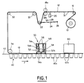
- the reference 10 designates a roll of a strip or film 12 of covers, for example of paper / polyethylene or polyethylene / aluminum composite, conventionally printed on one of its faces so as to define patterns individual covers 12a over a width corresponding to a given number of containers.
- the strip 12 comprises, at a step identical to the longidudinal step of the cover patterns, optical or spot indicators of a particular color or of a reflection or light absorption coefficient, conventionally produced during printing. These spots 14 are indicated by vertical dashes in FIG. 1, but it will be understood that in practice they lie in the plane of the strip 12.
- the strip 12 printed on its outer face in the roller 10, passes around a first return cylinder 16 and then between two pressing cylinders 18a and 18b appropriately controlled by a motor (not illustrated), to cause the advancement, controlled as will be seen below, of the strip.
- a photoelectric cell 20 is placed below the strip 12 between the cylinders 16 and 18b, so as to be able to read the locating spots 14 and send appropriate electrical signals to a control system (not illustrated).
- the strip 12 passes around a cylinder 22 which is mounted idly at one end of a rod or connecting rod 24 the other end of which is articulated at 26 around an axis parallel to the axis of the cylinder 22.
- a stop 28 makes it possible, in cooperation with the rod 24, to limit the stroke of the cylinder 22 upwards.
- the assembly made up of elements 22 to 28 constitutes a puppet whose role will be explained in detail below.
- Two return cylinders 30 and 32 are then provided which bring the strip successively horizontally then essentially vertically downwards in the direction of the containers.
- the reference 40 designates the continuous set of containers 40a, previously filled in a filling station not shown. As can be observed, the containers 40a are at this stage in one piece and integral with each other by their flanges 42a located in a common upper plane 42 of the containers.
- a mechanism for driving the containers (not illustrated and of the conventional type) makes it possible to move the said containers in the direction of the arrow A, at an appropriate pace and cadence.
- a return cylinder 34 is placed immediately above the plane 42, so that the cover strip extends parallel and above this plane, as illustrated.
- the set of containers, associated with its strip of covers of the same width, circulates step by step according to arrow F first of all towards a welding station, generally designated by the reference 50.
- This station essentially comprises a tool heater 52 which has a lower working surface 52a whose shape roughly corresponds to the shape of the flanges 42a, still unitary, of the containers.
- a peripheral welding of each cover 12a of the strip 12 is carried out on the associated flange 42a, in order to seal the container hermetically by producing a peelable cover.
- the welding tool here works simultaneously on two transverse rows of containers, this characteristic however being in no way limiting.
- the heating tool 52 in association with each of the two transverse rows of containers, two rows of pushers 54 positioned so as to be at least approximately centered on the respective containers.
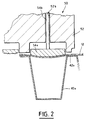
- Each pusher 54 has a head 54a which defines a lower surface of a slightly domed pusher, as illustrated, and a rod 54b extending upwards from the head in a guide bore 52b formed in the heating tool 52 to allow vertical sliding of the pushers.
- a member 54c forming a seat for the lower end of a compression spring 56, arranged vertically and bearing at its upper end on an upper wall 58 of the tool 50. It can be noted that the seat 54c of each pusher can cooperate with the upper surface of the heating tool 52 to limit the stroke of the pusher down, essentially to prevent it from falling when the welding tool is lifted. distance from containers.
- the set of containers, to which the strip of covers is welded is conveyed to a cutting station 60, constituted by a press of the conventional type and not described in detail, for separating the containers either in units , or in groups of an appropriate number.
- the welding tool 52 is then lifted vertically, with its pushers 54, to allow the containers to be advanced.
- the longitudinal pitch of the covers 12a of the film is slightly greater than the longitudinal pitch of the containers 40a.
- the double advance (receptacles and film) carried out has the effect of bringing the following two rows of receptacles, with the homologous part of the film, below the welding station 50. Due to the abovementioned pitch deviations, and by play possible of the puppet described above, making it possible to absorb any temporary shifts in longitudinal movement between the containers and the strip 12, it is understood that these movements are carried out without the containers having to effect a significant traction on said strip , and therefore without inducing annoying solicitation in the advance mechanisms.
- the individual covers 12a are well aligned with the receptacles to the right of the welding station, but that there is an offset to the left of it, equal to twice the difference between the longitudinal pitch of the covers and the longitudinal pitch of the containers in the case of treating the transverse rows two by two.
- the welding tool 50 is then lowered.
- the lower surfaces of the heads 54a of pushers then come, under the action of their compression springs 56, to urge with a measured force the central region of the homologous covers.
- This has the effect, by downward deformation of said central regions, of exerting on the strip 12 a slight traction, the amplitude of which is controlled by the puppet.
- the pushers 54 push the central zones of the covers downwards by deforming them until the rod 24 of the puppet comes to stop against its associated stop 28, in which case the stroke of the pushers down stops (the springs 56 are of course calibrated at a low value such that substantially no elongation is induced in the strip).
- the pitch of the covers 12a of the strip 12 is greater than the pitch of the containers by approximately 0.10 to 0.15 mm. In any event, this extra length is chosen so that it is always greater than the inaccuracies which may appear in the patterns of covers either during printing or within the roller 10 (differences in temperature, humidity, compression, ...), these inaccuracies being typically +/- 0.05 mm.
- the double advance containers / strip described above in this case will induce a less ample downward movement of the cylinder 22, and therefore a reduction in the spacing between the rod 24 and its stop 28 before the actuators 54 are actuated. Consequently, the action of the actuators 54 prior to welding will be of smaller amplitude, to take into account the punctual decrease in the offset between the pitch of the lids and the pitch of the containers.
- the means described allow regulation to be carried out in a simple and effective manner making it possible to compensate for any imprecision in the patterns of covers.
- the pushers 54 have a significant weight, one can omit the associated springs 56, the deformation of the central areas of the covers then effected by the sole play of the force of gravity of the pushers.
Landscapes
- Engineering & Computer Science (AREA)
- Mechanical Engineering (AREA)
- Closing Of Containers (AREA)
- Auxiliary Devices For And Details Of Packaging Control (AREA)
- Coating With Molten Metal (AREA)
- Containers And Plastic Fillers For Packaging (AREA)
- Making Paper Articles (AREA)
Claims (11)
- Verfahren zum Positionieren eines kontinuierlichen Deckelbandes (12) auf einer kontinuierlichen Anordnung (40) von Behältern vor dem Versiegeln, gemäß dem man wiederholt die folgenden Schritte durchführt:- Antreiben der Behälteranordnung in der Nähe einer Versiegelungseinrichtung (50) gemäß einer Teilung, die gleich einer Teilung von Behältern in Längsrichtung (Längsteilung) oder einem Vielfachen dieser Teilung ist,- gleichzeitig Freigeben des Deckelbandes auf einer Länge, die gleich einer Längsteilung von Deckeln, etwas größer als die Längsteilung von Behältern oder auch ein Vielfaches dieser Teilung ist, wobei das Band durch die Behälteranordnung mitgeführt wird,- in der Nähe der Versiegelungseinrichtung Ausüben einer Deformation auf eine zentrale Zone jedes Deckels, derart daß Grenzen zwischen noch nicht versiegelten Deckeln verschoben werden, um sie übereinanderliegend mit entsprechenden Behältergrenzen anzuordnen.
- Verfahren nach Anspruch 1, bei dem die Teilung der Deckel (12a) des Deckelbandes eine vorbestimmte, absolute Ungenauigkeit aufweist, dadurch gekennzeichnet, daß der Unterschied zwischen der Längsteilung der Deckel und der Längsteilung der Behälter (40a) etwas größer ist als der positive maximale Wert dieser Ungenauigkeit.
- Verfahren nach Anspruch 1 oder 2, dadurch gekennzeichnet, daß der Schritt der Deformation durch Anwendung eines Druckes nach unten in Richtung des Innenraumes jedes Behälters ausgeführt wird.
- Verfahren nach Anspruch 3, dadurch gekennzeichnet, daß man den Einfluß der Deformation und die resultierende Verschiebungsamplitude auf einen geeigneten Wert begrenzt, indem man dem Band eine begrenzte Bewegung nach dem Freigeben erlaubt.
- Vorrichtung zum Positionieren eines kontinuierlichen Deckelbandes auf einer kontinuierlichen Anordnung von Behältern vor dem Versiegeln mit einen Mechanismus zum Vorschub der Behälteranordnung in der Nähe einer Versiegelungseinrichtung (50) gemäß einer Teilung, die gleich einer Längsteilung von Behältern (40a) oder einem Vielfachen dieser Teilung ist, dadurch gekennzeichnet, daß sie- einen Mechanismus (18a, 18b, 20) zum Vorschub des Deckelbandes zum Freigeben des Bandes auf einer Länge, die gleich einer Längsteilung von Deckeln (12a), etwas größer als die Längsteilung von Behältern oder auch ein Vielfaches dieser Teilung ist, wobei das Band durch den Vorschub der Behälteranordnung mitgeführt wird,- eine in der Versiegelungseinrichtung vorgesehene Einrichtung (54, 56) zum Ausüben einer Deformation auf zentrale Zonen der Deckel vor dem Versiegeln,- eine Einrichtung (22, 24, 26, 28) zur Regulierung der Amplitude der Deformation, derart, daß Grenzen zwischen noch nicht versiegelten Deckeln verschoben werden, um sie übereinanderliegend mit entsprechenden Behältergrenzen anzuordnen,aufweist.
- Vorrichtung nach Anspruch 5, dadurch gekennzeichnet, daß die Deformationseinrichtung eine Anordnung von Stößeln (54) aufweist, die verschiebbar in einem Versiegelungswerkzeug (52) aufgenommen sind.
- Vorrichtung nach Anspruch 6, dadurch gekennzeichnet, daß die Stößel (54) nach unten durch elastische Mittel (56) belastet werden.
- Vorrichtung nach einem der Ansprüche 6 und 7, dadurch gekennzeichnet, daß jeder Stößel einen Kopf (54a) mit einer unteren gewölbten Fläche aufweist.
- Vorrichtung nach einem der Ansprüche 5 bis 8, dadurch gekennzeichnet, daß die Regulierungseinrichtung eine Tänzerrolle (22, 24, 26), die auf dem Band stromabwärts des Bandvorschubmechanismus in Verbindung mit einem Anschlag (28) vorgesehen ist, aufweist.
- Vorrichtung nach einem der Ansprüche 5 bis 9, dadurch gekennzeichnet, daß der Bandvorschubmechanismus mit Motorantrieb versehene Zylinder (18a, 18b) aufweist, die in Abhängigkeit von Signalen gesteuert werden, die von einem Fühler (20) für Markierungen des Bandes (14) aufgenommen werden.
- Vorrichtung nach einem der Ansprüche 5 bis 10, bei dem die Deckelteilung (12a) des Deckelbandes eine vorbestimmte, absolute Ungenauigkeit aufweist, dadurch gekennzeichnet, daß der Unterschied zwischen der Längsteilung der Deckel und der Längsteilung der Behälter (40a) etwas größer ist als der positive maximale Wert dieser Ungenauigkeit.
Applications Claiming Priority (2)
| Application Number | Priority Date | Filing Date | Title |
|---|---|---|---|
| FR9015130 | 1990-12-03 | ||
| FR9015130A FR2669888B1 (fr) | 1990-12-03 | 1990-12-03 | Procede et dispositif de positionnement avant scellage d'une bande de couvercles sur un ensemble de recipients. |
Publications (2)
| Publication Number | Publication Date |
|---|---|
| EP0489646A1 EP0489646A1 (de) | 1992-06-10 |
| EP0489646B1 true EP0489646B1 (de) | 1994-09-21 |
Family
ID=9402851
Family Applications (1)
| Application Number | Title | Priority Date | Filing Date |
|---|---|---|---|
| EP91403271A Expired - Lifetime EP0489646B1 (de) | 1990-12-03 | 1991-12-03 | Verfahren und Vorrichtung zum Positionieren von einer Deckelfolienbahn vor deren Versiegelung an einer Behältereinheit |
Country Status (9)
| Country | Link |
|---|---|
| US (1) | US5230205A (de) |
| EP (1) | EP0489646B1 (de) |
| JP (1) | JPH07110643B2 (de) |
| AT (1) | ATE111841T1 (de) |
| AU (1) | AU649192B2 (de) |
| CA (1) | CA2056848A1 (de) |
| DE (1) | DE69104172T2 (de) |
| ES (1) | ES2064960T3 (de) |
| FR (1) | FR2669888B1 (de) |
Families Citing this family (24)
| Publication number | Priority date | Publication date | Assignee | Title |
|---|---|---|---|---|
| SE502434C2 (sv) * | 1994-02-10 | 1995-10-16 | Lars Olof Andersson | Förfarande och anordning för tillslutning av åtminstone den ena änden av ett rör samt för tillslutningen avsedd plugg |
| US5674347A (en) * | 1994-06-10 | 1997-10-07 | Johnson & Johnson Vision Products, Inc. | Apparatus and method for preparing printing labels |
| DE19503458B4 (de) * | 1995-02-03 | 2007-10-31 | Rüdiger Haaga GmbH | Vorrichtung zum Verschließen einer Füllöffnung |
| US5720157A (en) * | 1996-03-28 | 1998-02-24 | Si Handling Systems, Inc. | Automatic order selection system and method of operating |
| CH692849A5 (de) * | 1997-09-15 | 2002-11-29 | Kammann Maschf Werner | Verfahren zur Kennzeichnung von Gegenständen. |
| SE517571C2 (sv) * | 1998-07-29 | 2002-06-18 | Tetra Laval Holdings & Finance | Metod för krympfilmsinslagning |
| FR2784572B1 (fr) * | 1998-10-15 | 2001-02-09 | Instr Medecine Veterinaire | Procede de fabrication d'un element constitue d'un support et d'une membrane qui y est soudee, en particulier d'un bouchon de paillette, et ensemble membrane support obtenu par ce procede |
| ES2245706T3 (es) * | 2000-11-24 | 2006-01-16 | Cfs Germany Gmbh | Procedimiento y dispositivo para colocar bandas de pelicula de un dispositivo de embalaje. |
| US20030021969A1 (en) * | 2001-06-29 | 2003-01-30 | Aloisi Robert J. | Reflective heat-shrinking film |
| US20030015274A1 (en) * | 2001-06-29 | 2003-01-23 | Mallman A. James | Reflective hood for heat-shrinking film onto an open-topped container and method of using same |
| US7184855B2 (en) | 2002-03-13 | 2007-02-27 | Stingel Iii Frederick J | Automated container storage and delivery system |
| US6729836B2 (en) * | 2002-03-13 | 2004-05-04 | Stingel, Iii Frederick J. | Automated container storage and delivery system |
| US7089718B2 (en) * | 2002-06-10 | 2006-08-15 | Green-Line Products, Inc. | Apparatus for heat-shrinking film onto an open-topped container and method of using same |
| US20040035088A1 (en) * | 2002-06-10 | 2004-02-26 | Loeffler Herbert H. | Container positioning device |
| US20040068968A1 (en) * | 2002-06-10 | 2004-04-15 | Biba Scott I. | Modular rotational assembly |
| US6871116B2 (en) * | 2002-10-17 | 2005-03-22 | Vertique, Inc. | Determining pallet case configurations for placement by a robot |
| FR2867453B1 (fr) * | 2004-03-15 | 2006-05-12 | Cefma | Dispositif de pose sur un fardeau d'une poignee preparee |
| DE102010004635B4 (de) * | 2010-01-14 | 2011-09-22 | Multivac Sepp Haggenmüller Gmbh & Co. Kg | Siegelwerkzeug |
| KR200470945Y1 (ko) | 2011-09-15 | 2014-01-21 | (주)아모레퍼시픽 | 화장품 토출구 자동삽입장치 |
| JP2016166039A (ja) * | 2015-03-10 | 2016-09-15 | 大日本印刷株式会社 | ラベル貼着装置およびラベル貼着方法 |
| JP6583709B2 (ja) * | 2015-03-02 | 2019-10-02 | 大日本印刷株式会社 | 容器シール装置および容器シール方法 |
| WO2016140197A1 (ja) * | 2015-03-02 | 2016-09-09 | 大日本印刷株式会社 | 容器シール装置および容器シール方法 |
| ES3042258T3 (en) * | 2019-05-10 | 2025-11-19 | Gea Food Solutions Germany Gmbh | Packing machine without dancers |
| JP2023172472A (ja) * | 2022-05-24 | 2023-12-06 | 株式会社寺岡精工 | 包装装置 |
Family Cites Families (10)
| Publication number | Priority date | Publication date | Assignee | Title |
|---|---|---|---|---|
| FR1330729A (fr) * | 1961-07-28 | 1963-06-28 | Perfectionnements apportés aux machines à former des récipients clos par un couvercle doté d'une étiquette | |
| US3238691A (en) * | 1963-03-06 | 1966-03-08 | Nat Dairy Prod Corp | Packaging material register control |
| US3294301A (en) * | 1965-02-09 | 1966-12-27 | Standard Packaging Corp | Web registration system |
| US3374602A (en) * | 1965-08-18 | 1968-03-26 | Mahaffy & Harder Eng Co | Indicia registration method and apparatus |
| US3555768A (en) * | 1968-02-26 | 1971-01-19 | Continental Can Co | Method and apparatus for handling and registering webs for forming packages |
| GB1241425A (en) * | 1968-10-28 | 1971-08-04 | Sidaplax S A | Improvements in or relating to the closuring of containers |
| US3652363A (en) * | 1969-10-23 | 1972-03-28 | Phillips Petroleum Co | Film positioning apparatus |
| US3762125A (en) * | 1971-03-17 | 1973-10-02 | Morrell & Co John | Film registration apparatus |
| US4018028A (en) * | 1971-07-23 | 1977-04-19 | Societe D'application Plastique Mecanique Et Electronique, Plastimecanique S.A. | Arrangement for aligning heat-sealable lids on mating product-filled containers |
| US3861983A (en) * | 1973-02-12 | 1975-01-21 | Phillips Petroleum Co | Film positioning apparatus |
-
1990
- 1990-12-03 FR FR9015130A patent/FR2669888B1/fr not_active Expired - Fee Related
-
1991
- 1991-12-02 AU AU88367/91A patent/AU649192B2/en not_active Expired
- 1991-12-02 US US07/800,954 patent/US5230205A/en not_active Expired - Lifetime
- 1991-12-03 EP EP91403271A patent/EP0489646B1/de not_active Expired - Lifetime
- 1991-12-03 DE DE69104172T patent/DE69104172T2/de not_active Expired - Lifetime
- 1991-12-03 CA CA002056848A patent/CA2056848A1/fr not_active Abandoned
- 1991-12-03 ES ES91403271T patent/ES2064960T3/es not_active Expired - Lifetime
- 1991-12-03 AT AT91403271T patent/ATE111841T1/de not_active IP Right Cessation
- 1991-12-03 JP JP3348319A patent/JPH07110643B2/ja not_active Expired - Lifetime
Also Published As
| Publication number | Publication date |
|---|---|
| EP0489646A1 (de) | 1992-06-10 |
| CA2056848A1 (fr) | 1992-06-04 |
| ATE111841T1 (de) | 1994-10-15 |
| DE69104172D1 (de) | 1994-10-27 |
| FR2669888A1 (fr) | 1992-06-05 |
| JPH07110643B2 (ja) | 1995-11-29 |
| FR2669888B1 (fr) | 1993-10-22 |
| ES2064960T3 (es) | 1995-02-01 |
| US5230205A (en) | 1993-07-27 |
| JPH072204A (ja) | 1995-01-06 |
| AU649192B2 (en) | 1994-05-12 |
| AU8836791A (en) | 1992-06-04 |
| DE69104172T2 (de) | 1995-05-11 |
Similar Documents
| Publication | Publication Date | Title |
|---|---|---|
| EP0489646B1 (de) | Verfahren und Vorrichtung zum Positionieren von einer Deckelfolienbahn vor deren Versiegelung an einer Behältereinheit | |
| EP0693424B1 (de) | Verfahren und Vorrichtung zur Herstellung von Verpackungszuschnitten | |
| FR2612497A1 (fr) | Emballage pour le conditionnement de produits sous un film transparent, procede pour la realisation de cet emballage et dispositif pour la mise en oeuvre de ce procede | |
| EP0000851B1 (de) | Automatische Vorrichtung zum Zerteilen eines thermoplastischen Schlauches und zum Überziehen von Behältern mittels dieser Schlauchteilen | |
| FR2672542A1 (fr) | Dispositif de detection, dans une machine, de la position de contact de deux cylindres d'axes paralleles. | |
| FR2765191A1 (fr) | Procede et machine de collage automatique d'un film plastique thermoretractable sur le fond d'une caisse ouverte | |
| EP1510316B1 (de) | Verfahren zum herstellen von platten aus hydraulischem bindemittel, fertigungsstrasse zur herstellung derartiger platten und vorrichtung zum prägen | |
| EP0057144B1 (de) | Maschine zum Verpacken von zylinderförmigen Artikeln in kreisförmigen Zuschnitten, geformt aus Bahnen von thermoplastischem Verpackungsmaterial | |
| EP0394707A1 (de) | Vorrichtung zum nacheinander Zuführen von Platten zu einer Verarbeitungsmaschine | |
| CH682995A5 (fr) | Dispositif d'interception de feuilles déposées sur le haut d'une pile dans une machine de production d'emballages. | |
| EP0689993A1 (de) | Maschine zum Verpacken mittels flexiblen Folienmaterials sowie die erhaltene Verpackung | |
| EP1361030B1 (de) | Verfahren zum Herstellen von Platten aus hydraulischem Bindemittel sowie Fertigungsstrasse zur Herstellung derartiger Platten | |
| WO2009068823A2 (fr) | Systeme de fabrication a la chaine de conteneurs en film plastique semi-rigide epais | |
| FR2771333A1 (fr) | Procede et machines pour le rainage et le decoupage en ligne d'un format brut destine a la formation d'emballages en carton | |
| EP0611187A1 (de) | Rotierende Schneidvorrichtung | |
| FR2767282A1 (fr) | Procede et machine pour le montage d'une caisse a section polygonale a partir d'une decoupe a plat en carton ondule | |
| EP1944239A1 (de) | Verfahren zur Herstellung von Verpackungen für Blumen- und/oder Pflanzenkompositionen | |
| EP1725393B1 (de) | Maschine und verfahren zur herstellung einer platte durch verwendung eines dorns | |
| FR2483357A1 (fr) | Machine d'emballage comportant un outil d'estampage | |
| FR2754516A1 (fr) | Dispositif de conditionnement en continu de cachets en bandes d'etuis individuels | |
| FR2669909A1 (fr) | Dispositif de decoupe de manchons a partir d'une gaine tubulaire devidee en continu. | |
| BE862009A (fr) | Procede pour la fabrication de liasses de sacs et machine pour la mise en oeuvre de ce procede | |
| EP1562760B1 (de) | Vorrichtung zum markieren von verformbaren komplexen durch prägen | |
| CH282151A (fr) | Procédé de fabrication d'une capsule plisée pour bouteille, capsule obtenue par ce procédé et dispositif pour la mise en oeuvre du procédé. | |
| BE553910A (de) |
Legal Events
| Date | Code | Title | Description |
|---|---|---|---|
| PUAI | Public reference made under article 153(3) epc to a published international application that has entered the european phase |
Free format text: ORIGINAL CODE: 0009012 |
|
| AK | Designated contracting states |
Kind code of ref document: A1 Designated state(s): AT BE CH DE DK ES FR GB GR IT LI LU NL SE |
|
| 17P | Request for examination filed |
Effective date: 19921106 |
|
| 17Q | First examination report despatched |
Effective date: 19931215 |
|
| GRAA | (expected) grant |
Free format text: ORIGINAL CODE: 0009210 |
|
| AK | Designated contracting states |
Kind code of ref document: B1 Designated state(s): AT BE CH DE DK ES FR GB GR IT LI LU NL SE |
|
| PG25 | Lapsed in a contracting state [announced via postgrant information from national office to epo] |
Ref country code: IT Free format text: LAPSE BECAUSE OF FAILURE TO SUBMIT A TRANSLATION OF THE DESCRIPTION OR TO PAY THE FEE WITHIN THE PRE;WARNING: LAPSES OF ITALIAN PATENTS WITH EFFECTIVE DATE BEFORE 2007 MAY HAVE OCCURRED AT ANY TIME BEFORE 2007. THE CORRECT EFFECTIVE DATE MAY BE DIFFERENT FROM THE ONE RECORDED.SCRIBED TIME-LIMIT Effective date: 19940921 Ref country code: DK Effective date: 19940921 Ref country code: AT Effective date: 19940921 Ref country code: GR Free format text: LAPSE BECAUSE OF FAILURE TO SUBMIT A TRANSLATION OF THE DESCRIPTION OR TO PAY THE FEE WITHIN THE PRESCRIBED TIME-LIMIT Effective date: 19940921 Ref country code: NL Effective date: 19940921 |
|
| REF | Corresponds to: |
Ref document number: 111841 Country of ref document: AT Date of ref document: 19941015 Kind code of ref document: T |
|
| REF | Corresponds to: |
Ref document number: 69104172 Country of ref document: DE Date of ref document: 19941027 |
|
| PG25 | Lapsed in a contracting state [announced via postgrant information from national office to epo] |
Ref country code: SE Effective date: 19941221 |
|
| PG25 | Lapsed in a contracting state [announced via postgrant information from national office to epo] |
Ref country code: CH Effective date: 19941231 Ref country code: LU Free format text: LAPSE BECAUSE OF NON-PAYMENT OF DUE FEES Effective date: 19941231 Ref country code: LI Effective date: 19941231 Ref country code: BE Effective date: 19941231 |
|
| REG | Reference to a national code |
Ref country code: ES Ref legal event code: FG2A Ref document number: 2064960 Country of ref document: ES Kind code of ref document: T3 |
|
| GBT | Gb: translation of ep patent filed (gb section 77(6)(a)/1977) |
Effective date: 19950201 |
|
| NLV1 | Nl: lapsed or annulled due to failure to fulfill the requirements of art. 29p and 29m of the patents act | ||
| BERE | Be: lapsed |
Owner name: S.A. ERCA Effective date: 19941231 |
|
| PLBE | No opposition filed within time limit |
Free format text: ORIGINAL CODE: 0009261 |
|
| STAA | Information on the status of an ep patent application or granted ep patent |
Free format text: STATUS: NO OPPOSITION FILED WITHIN TIME LIMIT |
|
| REG | Reference to a national code |
Ref country code: CH Ref legal event code: PL |
|
| 26N | No opposition filed | ||
| REG | Reference to a national code |
Ref country code: GB Ref legal event code: IF02 |
|
| REG | Reference to a national code |
Ref country code: FR Ref legal event code: CD |
|
| PGFP | Annual fee paid to national office [announced via postgrant information from national office to epo] |
Ref country code: FR Payment date: 20110110 Year of fee payment: 20 |
|
| PGFP | Annual fee paid to national office [announced via postgrant information from national office to epo] |
Ref country code: GB Payment date: 20101123 Year of fee payment: 20 |
|
| PGFP | Annual fee paid to national office [announced via postgrant information from national office to epo] |
Ref country code: DE Payment date: 20101209 Year of fee payment: 20 |
|
| PGFP | Annual fee paid to national office [announced via postgrant information from national office to epo] |
Ref country code: ES Payment date: 20101223 Year of fee payment: 20 |
|
| REG | Reference to a national code |
Ref country code: DE Ref legal event code: R071 Ref document number: 69104172 Country of ref document: DE |
|
| REG | Reference to a national code |
Ref country code: DE Ref legal event code: R071 Ref document number: 69104172 Country of ref document: DE |
|
| REG | Reference to a national code |
Ref country code: GB Ref legal event code: PE20 Expiry date: 20111202 |
|
| REG | Reference to a national code |
Ref country code: ES Ref legal event code: FD2A Effective date: 20120220 |
|
| PG25 | Lapsed in a contracting state [announced via postgrant information from national office to epo] |
Ref country code: GB Free format text: LAPSE BECAUSE OF EXPIRATION OF PROTECTION Effective date: 20111202 |
|
| PG25 | Lapsed in a contracting state [announced via postgrant information from national office to epo] |
Ref country code: ES Free format text: LAPSE BECAUSE OF EXPIRATION OF PROTECTION Effective date: 20111204 |
|
| PG25 | Lapsed in a contracting state [announced via postgrant information from national office to epo] |
Ref country code: DE Free format text: LAPSE BECAUSE OF EXPIRATION OF PROTECTION Effective date: 20111204 |