EP0489040B1 - Verfahren und einrichtung zum kopieren von magnetbändern - Google Patents
Verfahren und einrichtung zum kopieren von magnetbändern Download PDFInfo
- Publication number
- EP0489040B1 EP0489040B1 EP90912108A EP90912108A EP0489040B1 EP 0489040 B1 EP0489040 B1 EP 0489040B1 EP 90912108 A EP90912108 A EP 90912108A EP 90912108 A EP90912108 A EP 90912108A EP 0489040 B1 EP0489040 B1 EP 0489040B1
- Authority
- EP
- European Patent Office
- Prior art keywords
- control track
- recording
- magnetic tapes
- recorded
- address
- Prior art date
- Legal status (The legal status is an assumption and is not a legal conclusion. Google has not performed a legal analysis and makes no representation as to the accuracy of the status listed.)
- Expired - Lifetime
Links
Images

Classifications
-
- G—PHYSICS
- G11—INFORMATION STORAGE
- G11B—INFORMATION STORAGE BASED ON RELATIVE MOVEMENT BETWEEN RECORD CARRIER AND TRANSDUCER
- G11B27/00—Editing; Indexing; Addressing; Timing or synchronising; Monitoring; Measuring tape travel
- G11B27/10—Indexing; Addressing; Timing or synchronising; Measuring tape travel
- G11B27/19—Indexing; Addressing; Timing or synchronising; Measuring tape travel by using information detectable on the record carrier
- G11B27/28—Indexing; Addressing; Timing or synchronising; Measuring tape travel by using information detectable on the record carrier by using information signals recorded by the same method as the main recording
- G11B27/32—Indexing; Addressing; Timing or synchronising; Measuring tape travel by using information detectable on the record carrier by using information signals recorded by the same method as the main recording on separate auxiliary tracks of the same or an auxiliary record carrier
- G11B27/322—Indexing; Addressing; Timing or synchronising; Measuring tape travel by using information detectable on the record carrier by using information signals recorded by the same method as the main recording on separate auxiliary tracks of the same or an auxiliary record carrier used signal is digitally coded
- G11B27/324—Duty cycle modulation of control pulses, e.g. VHS-CTL-coding systems, RAPID-time code, VASS- or VISS-cue signals
-
- G—PHYSICS
- G11—INFORMATION STORAGE
- G11B—INFORMATION STORAGE BASED ON RELATIVE MOVEMENT BETWEEN RECORD CARRIER AND TRANSDUCER
- G11B5/00—Recording by magnetisation or demagnetisation of a record carrier; Reproducing by magnetic means; Record carriers therefor
- G11B5/86—Re-recording, i.e. transcribing information from one magnetisable record carrier on to one or more similar or dissimilar record carriers
-
- G—PHYSICS
- G11—INFORMATION STORAGE
- G11B—INFORMATION STORAGE BASED ON RELATIVE MOVEMENT BETWEEN RECORD CARRIER AND TRANSDUCER
- G11B27/00—Editing; Indexing; Addressing; Timing or synchronising; Monitoring; Measuring tape travel
- G11B27/02—Editing, e.g. varying the order of information signals recorded on, or reproduced from, record carriers
- G11B27/022—Electronic editing of analogue information signals, e.g. audio or video signals
- G11B27/024—Electronic editing of analogue information signals, e.g. audio or video signals on tapes
-
- G—PHYSICS
- G11—INFORMATION STORAGE
- G11B—INFORMATION STORAGE BASED ON RELATIVE MOVEMENT BETWEEN RECORD CARRIER AND TRANSDUCER
- G11B27/00—Editing; Indexing; Addressing; Timing or synchronising; Monitoring; Measuring tape travel
- G11B27/02—Editing, e.g. varying the order of information signals recorded on, or reproduced from, record carriers
- G11B27/031—Electronic editing of digitised analogue information signals, e.g. audio or video signals
- G11B27/032—Electronic editing of digitised analogue information signals, e.g. audio or video signals on tapes
-
- G—PHYSICS
- G11—INFORMATION STORAGE
- G11B—INFORMATION STORAGE BASED ON RELATIVE MOVEMENT BETWEEN RECORD CARRIER AND TRANSDUCER
- G11B27/00—Editing; Indexing; Addressing; Timing or synchronising; Monitoring; Measuring tape travel
- G11B27/10—Indexing; Addressing; Timing or synchronising; Measuring tape travel
-
- G—PHYSICS
- G11—INFORMATION STORAGE
- G11B—INFORMATION STORAGE BASED ON RELATIVE MOVEMENT BETWEEN RECORD CARRIER AND TRANSDUCER
- G11B2220/00—Record carriers by type
- G11B2220/90—Tape-like record carriers
-
- G—PHYSICS
- G11—INFORMATION STORAGE
- G11B—INFORMATION STORAGE BASED ON RELATIVE MOVEMENT BETWEEN RECORD CARRIER AND TRANSDUCER
- G11B2220/00—Record carriers by type
- G11B2220/90—Tape-like record carriers
- G11B2220/91—Helical scan format, wherein tracks are slightly tilted with respect to tape direction, e.g. VHS, DAT, DVC, AIT or exabyte
Definitions
- the invention relates to a method for copying magnetic tapes, in particular audio or video or data magnetic tapes.
- the invention also relates to a device for carrying out the method.
- useful information located on an already recorded information carrier is reproduced by a playback device, forwarded via a transmission link to a recording device and recorded on an information carrier to be recorded on.
- the same useful information as on the original is contained on the information carrier to be recorded on.
- Any additional information that is recorded in certain recording standards - for example in the VHS standard - for device-internal control of the playback operation in addition to the actual useful information is not affected by the copying process.
- Such control information is generated in the device during the recording process and is used in video recorders, for example, to switch between several scanning heads to synchronize a rotating head disc during later playback.
- the synchronization pulses are recorded on a control track or control track ("CTL") parallel to the tape edge and consist essentially of sharp transitions from a north to a south or from a south to a north magnetization, whereby it is sufficient to continuously consider two successive transitions of the same type, for example from north to south magnetization, between which, for example, a defined time period of 40 msec elapses during recording.
- the respective other transitions i.e. the transitions from south to north magnetization in the example mentioned, are not required for synchronization and can therefore be varied within certain limits within their relative position within the aforementioned 40 msec time window, without the original task of Synchronization by means of the control track is impaired.
- VHS index search system VHS index search system
- VASS brands VHS address search system
- the object of the invention is to transmit additional information contained in a control track when copying magnetic tapes.
- the recording preferably takes place in the time window that can be accessed at the same time as the recording of the control track.
- the digital information "0” or “1” can be transmitted via one of the so-called SCART connecting lines, wherein a level of 0 or 5 volts can correspond to the digital information "0" or "1".
- the digital information on the reproducing device side in one Buffer memories are buffered until an address consisting of several bits has been completely read in; this complete address can then be transmitted to the recording device via serial interfaces and an infrared path arranged between them, where it is then recorded again in a digitally coded form with the control track.
- D2B bus has been specified by the International Electrotechnical Commission (IEC) in a document entitled "Project No. 84.12.05001" (June 1988 edition).
- IEC International Electrotechnical Commission
- serial transmission that is to say bit by bit
- the D2B bus is used to transmit the data in accordance with the aforementioned infrared transmission format. The latter has the advantage over continuous serial transmission that it only loads the bus for a short time and is therefore preferable to continuous serial transmission.
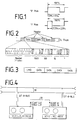
- Fig. 1 is a 100% designated, in the VHS standard for the 625 line / 50Hz / PAL television transmission method 40 msec comprehensive time window from a positive edge (corresponding to approximately a north / south magnetization transition) to the next positive edge shown. If the negative flank occurring between the two positive flanks (corresponding to a south / north magnetization transition) is in the range 60% ⁇ 5% (FIG. 1a), the digital value "0" is thereby coded, the negative flank is located Flank, however, in the range of 27.5% ⁇ 2.5% (Fig. 1b), so that the digital value "1" is encoded.
- FIG. 2 schematically shows how an address code recorded on the control track of a VHS magnetic tape is structured.
- Such an address code consists of four headers, each consisting of eleven bits.
- a data word is inserted between two headers, each of these data words consisting of four BCD digits, which in turn consist of four bits.
- the headers are structured as follows: a first bit "0" is followed by nine bits "1", then a bit "0".
- a header thus consists of a total of eleven bits.
- the position of the four BCD digits is defined according to the recording direction as thousands, hundreds, tens or ones.
- the initial "0" of the first header in the recording direction serves as the reference position.
- FIG. 3 shows an infrared transmission format for transmitting an address contained on the control track.
- this address consists of four BCD digits, so that the number range from 0000 to 9999 is available.
- each of these digits is symbolically labeled "DATA", but they can nevertheless have different values.
- a command word CMD presented to the BCD digits provides information about what type of data is being sent or received.
- Transmitter ICs from Mitsubishi Electric Corporation, 2-3 marunouchi, Tokyo, Japan, for example, can be used as integrated circuits for transmitters for such an infrared transmission link, which generate a format corresponding to the transmission format shown in FIG. 3 M 50467 serve.
- FIG. 4 shows an exemplary embodiment of a device according to the invention for carrying out the copying method in a block diagram.
- a first video recorder VCR1 is in playback mode
- a second video recorder VCR2 is in recording mode.
- the two recorders VCR1, VCR2 are connected to one another via a line 20, which can be a SCART or a video line.
- This line 20 transmits image and sound from one (VCR1) to another (VCR2) video recorder in a conventional manner.
- the video recorders VCR1, VCR2 are also both connected to a D2B bus 30, via which they can exchange data and commands with one another in accordance with the standard defined by the IEC.
- first recorder VCR 1 digital data, such as VISS or VASS marks, corresponding to a control / recording head ("CTL head") assigned to the control track and a coding / decoding electronics belonging to it when playing the tape on the control track Data, recognized, for example, these are transmitted via the D2B bus 30 to the second video recorder VCR2, where they are then recorded by means of its CTL head and the coding / decoding electronics assigned to it during the ongoing recording process at the next possible opportunity in digitally coded form with the control track.
- CTL head control / recording head
- the data coded digitally in the control track can also be transmitted in the form of complete data words; this then takes place, for example, according to the infrared transmission format described for FIG. 3.
- Any other data bus can also be used instead of the D2B bus.
- the still free pins of the SCART line 20 can be provided for this.
- the recording / playback head (“CTL" head) 51 of the recorder VCR1 assigned to the control track of the tape 50 reads out the data contained on the control track in the playback mode.
- This data is sent via lines 52 to a so-called servo processor ⁇ P1, which processes the control information contained therein in accordance with the relevant recording standard - here, for example, in accordance with the VHS standard - in accordance with the standard, thereby ensuring, for example, that the video heads of the VCR1 recorder are controlled correctly.
- the data relating to the tape marks also go via a serial interface 53 to a so-called keyboard processor ⁇ P2, which reads and processes the data.
- the keyboard processor ⁇ P2 controls a display unit with which the marks can be displayed, for example as decimal numbers or as alphanumeric characters.
- the storage of tape marks - for example in the recording mode not present here but in the VCR2 video recorder - can be controlled by the keyboard processor ⁇ P2.
- the data relating to the band marks are processed in accordance with the protocol to be transmitted (D2B bus or an otherwise provided bus system).
- the keyboard processor ⁇ P2 also controls the transfer of the codes relating to the band marks to or from a D2B interface via a line 54, which is connected via lines 55 to the D2B bus 30 (FIG. 4).
- the codes are forwarded via this D2B bus 30 to the video recorder VCR2 provided for recording (FIG. 4).
- the video recorder VCR2 they are recorded in the corresponding reverse manner as in the video recorder VCR1 together with the control data generated by the servo processor there by means of the CTL head of the video recorder VCR2 on the control track of the tape intended for the copy.
- the D2B interface and D2B bus are again mentioned above as representative of other suitable bus systems.
- the I2C bus system, RS232 interface connections or the like can be provided for this purpose.
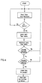
- FIG. 6 shows a flowchart for a program running in the keyboard processor ⁇ P2 using the example of the video recorder VCR1, which is provided here as a playback device. It goes without saying that a correspondingly adapted program is provided for the recording operation, as shown for the video recorder VCR2 in FIG. 4. It is further understood that the VCR1 and VCR2 are preferably set up for both playback and recording modes.
- the data for the transmission protocol are generated and finally output to the D2B bus lines via the D2B interface of the VCR VCR1.
- the program starts again with a jump back to the starting point.
Landscapes
- Engineering & Computer Science (AREA)
- Multimedia (AREA)
- Signal Processing For Digital Recording And Reproducing (AREA)
- Television Signal Processing For Recording (AREA)
- Liquid Developers In Electrophotography (AREA)
- Printers Or Recording Devices Using Electromagnetic And Radiation Means (AREA)
- Management Or Editing Of Information On Record Carriers (AREA)
- Indexing, Searching, Synchronizing, And The Amount Of Synchronization Travel Of Record Carriers (AREA)
- Combination Of More Than One Step In Electrophotography (AREA)
Priority Applications (1)
| Application Number | Priority Date | Filing Date | Title |
|---|---|---|---|
| AT90912108T ATE99075T1 (de) | 1989-08-25 | 1990-08-18 | Verfahren und einrichtung zum kopieren von magnetbaendern. |
Applications Claiming Priority (4)
| Application Number | Priority Date | Filing Date | Title |
|---|---|---|---|
| DE3928190 | 1989-08-25 | ||
| DE3928190 | 1989-08-25 | ||
| DE3932059 | 1989-08-26 | ||
| DE3932059A DE3932059A1 (de) | 1989-08-25 | 1989-08-26 | Verfahren und einrichtung zum kopieren von magnetbaendern |
Publications (2)
| Publication Number | Publication Date |
|---|---|
| EP0489040A1 EP0489040A1 (de) | 1992-06-10 |
| EP0489040B1 true EP0489040B1 (de) | 1993-12-22 |
Family
ID=25884432
Family Applications (1)
| Application Number | Title | Priority Date | Filing Date |
|---|---|---|---|
| EP90912108A Expired - Lifetime EP0489040B1 (de) | 1989-08-25 | 1990-08-18 | Verfahren und einrichtung zum kopieren von magnetbändern |
Country Status (12)
| Country | Link |
|---|---|
| EP (1) | EP0489040B1 (ko) |
| JP (1) | JPH05500725A (ko) |
| KR (1) | KR0158439B1 (ko) |
| CN (1) | CN1028573C (ko) |
| AT (1) | ATE99075T1 (ko) |
| AU (1) | AU6172090A (ko) |
| DE (2) | DE3932059A1 (ko) |
| ES (1) | ES2048500T3 (ko) |
| HK (1) | HK8596A (ko) |
| HU (1) | HUT63266A (ko) |
| MY (1) | MY106452A (ko) |
| WO (1) | WO1991003044A1 (ko) |
Families Citing this family (2)
| Publication number | Priority date | Publication date | Assignee | Title |
|---|---|---|---|---|
| GB9219709D0 (en) * | 1992-09-17 | 1992-10-28 | D2B Systems Co Ltd | Apparatus interconnected for the communication of control messages |
| MY128742A (en) * | 1994-12-22 | 2007-02-28 | Sony Corp | Recording medium for protecting copyrighted data |
Family Cites Families (1)
| Publication number | Priority date | Publication date | Assignee | Title |
|---|---|---|---|---|
| JPS5897737U (ja) * | 1981-12-22 | 1983-07-02 | 日本ビクター株式会社 | 磁気記録再生装置 |
-
1989
- 1989-08-26 DE DE3932059A patent/DE3932059A1/de not_active Withdrawn
-
1990
- 1990-08-18 KR KR1019920700421A patent/KR0158439B1/ko not_active IP Right Cessation
- 1990-08-18 DE DE90912108T patent/DE59003978D1/de not_active Expired - Fee Related
- 1990-08-18 HU HU92593A patent/HUT63266A/hu unknown
- 1990-08-18 WO PCT/EP1990/001360 patent/WO1991003044A1/de active IP Right Grant
- 1990-08-18 JP JP2511588A patent/JPH05500725A/ja active Pending
- 1990-08-18 AU AU61720/90A patent/AU6172090A/en not_active Abandoned
- 1990-08-18 ES ES90912108T patent/ES2048500T3/es not_active Expired - Lifetime
- 1990-08-18 EP EP90912108A patent/EP0489040B1/de not_active Expired - Lifetime
- 1990-08-18 AT AT90912108T patent/ATE99075T1/de not_active IP Right Cessation
- 1990-08-24 MY MYPI90001457A patent/MY106452A/en unknown
- 1990-08-25 CN CN90108177A patent/CN1028573C/zh not_active Expired - Fee Related
-
1996
- 1996-01-18 HK HK8596A patent/HK8596A/xx not_active IP Right Cessation
Non-Patent Citations (2)
| Title |
|---|
| Patent Abstracts of Japan, vol. 10, no. 259, E-434 abstract from JP-61 84180, publ. 1986-04-28 * |
| Patent Abstracts of Japan, vol. 12, no. 220, P-720, abstract from JP-63-14389, publ. 1988-01-21 * |
Also Published As
| Publication number | Publication date |
|---|---|
| KR0158439B1 (ko) | 1999-01-15 |
| ATE99075T1 (de) | 1994-01-15 |
| AU6172090A (en) | 1991-04-03 |
| CN1050455A (zh) | 1991-04-03 |
| HU9200593D0 (en) | 1992-05-28 |
| DE3932059A1 (de) | 1991-02-28 |
| JPH05500725A (ja) | 1993-02-12 |
| HK8596A (en) | 1996-01-26 |
| WO1991003044A1 (de) | 1991-03-07 |
| CN1028573C (zh) | 1995-05-24 |
| ES2048500T3 (es) | 1994-03-16 |
| DE59003978D1 (de) | 1994-02-03 |
| EP0489040A1 (de) | 1992-06-10 |
| KR920704275A (ko) | 1992-12-19 |
| MY106452A (en) | 1995-05-30 |
| HUT63266A (en) | 1993-07-28 |
Similar Documents
| Publication | Publication Date | Title |
|---|---|---|
| EP0363653B1 (de) | Verfahren zur Aufzeichnung und Wiedergabe des Inhaltsverzeichnisses einer Videomagnetbandkassette und Videorecorder zur Durchführung des Verfahrens | |
| EP0424653B1 (de) | Videorecorder mit einer Einrichtung zur Abspeicherung des Inhaltsverzeichnisses eines aus einer Vielzahl von Magnetbandkassetten bestehenden Kassettenmagazins | |
| DE19513952C2 (de) | Sprachinformations-Übertragungssystem | |
| DE2205893A1 (de) | Verfahren und Vorrichtung zur automatischen Montage von Fernsehinformationen | |
| EP0090292A2 (de) | Gerätekombination von Geräten der Unterhaltungselektronik mit einem Fernsehempfangsgerät und einem Videoaufnahme- und/oder -wiedergabegerät | |
| DE3621263A1 (de) | Aufzeichnungs- und wiedergabegeraet mit einem aufzeichnungstraeger | |
| EP0029946A1 (de) | Anordnung zum Speichern und Wiederauffinden von Stellen auf einem bandförmigen Aufzeichnungsträger in einem Aufnahme- und/oder Wiedergabegerät | |
| DE3016059A1 (de) | Bandstellensucher fuer ein pcm-aufzeichnungs- und -wiedergabe-geraet | |
| EP0489040B1 (de) | Verfahren und einrichtung zum kopieren von magnetbändern | |
| DE2132240A1 (de) | Rechnergesteuertes lehrsystem | |
| DE3827970C2 (ko) | ||
| DE4301441A1 (ko) | ||
| EP0362561B1 (de) | Verfahren zur Vermeidung des versehentlichen Ueberschreibens von auf einem Videomagnetband aufgezeichneten Videosignalabschnitten und Videomagnetbandrecorder zur Durchführung dieses Verfahrens | |
| DE3011810A1 (de) | Verfahren und geraet zum auffinden eines speicherplatzes auf einem aufzeichnungstraeger | |
| DE3705353A1 (de) | Automatische cueing-vorrichtung | |
| DE3401421A1 (de) | Adressendatenuebertagungsvorrichtung | |
| EP0344626A1 (de) | Anlage zur Wiedergabe von Videoaufzeichnungen von einem Videomagnetbandrecorder | |
| DE3008190A1 (de) | Verfahren zum markieren ausgewaehlter, zeitlich adressierter bild- und/oder tonereignisse | |
| EP1252626B1 (de) | Abspielgerät für komprimierte audiodaten | |
| EP0503519B1 (de) | Videorecorder mit einem Speicher zur Abspeicherung des Inhaltsverzeichnisses einer Vielzahl von Magnetbandkassetten | |
| EP0277549A2 (de) | Recorder | |
| DE3742468C1 (de) | Videoaufzeichnungsgeraet mit einem Programmwunschspeicher | |
| DE4312922B4 (de) | Aufzeichnungsgerät und Wiedergabegerät | |
| EP0401476B1 (de) | Videorecorder mit einer Einrichtung zum elektronischen Schneiden von Bildsignalen bei in Schrägspuren eines Magnetbandes aufgezeichneten Bild- und FM-Tonsignalen | |
| DD297273A5 (de) | Verfahren und einrichtung zum kopieren von magnetbaendern |
Legal Events
| Date | Code | Title | Description |
|---|---|---|---|
| PUAI | Public reference made under article 153(3) epc to a published international application that has entered the european phase |
Free format text: ORIGINAL CODE: 0009012 |
|
| 17P | Request for examination filed |
Effective date: 19920220 |
|
| AK | Designated contracting states |
Kind code of ref document: A1 Designated state(s): AT BE CH DE DK ES FR GB IT LI LU NL SE |
|
| 17Q | First examination report despatched |
Effective date: 19920708 |
|
| GRAA | (expected) grant |
Free format text: ORIGINAL CODE: 0009210 |
|
| STAA | Information on the status of an ep patent application or granted ep patent |
Free format text: STATUS: THE PATENT HAS BEEN GRANTED |
|
| ITF | It: translation for a ep patent filed |
Owner name: BARZANO' E ZANARDO MILA |
|
| AK | Designated contracting states |
Kind code of ref document: B1 Designated state(s): AT BE CH DE DK ES FR GB IT LI LU NL SE |
|
| PG25 | Lapsed in a contracting state [announced via postgrant information from national office to epo] |
Ref country code: SE Effective date: 19931222 Ref country code: NL Effective date: 19931222 Ref country code: DK Effective date: 19931222 Ref country code: BE Effective date: 19931222 |
|
| REF | Corresponds to: |
Ref document number: 99075 Country of ref document: AT Date of ref document: 19940115 Kind code of ref document: T |
|
| GBT | Gb: translation of ep patent filed (gb section 77(6)(a)/1977) |
Effective date: 19940105 |
|
| REF | Corresponds to: |
Ref document number: 59003978 Country of ref document: DE Date of ref document: 19940203 |
|
| REG | Reference to a national code |
Ref country code: ES Ref legal event code: FG2A Ref document number: 2048500 Country of ref document: ES Kind code of ref document: T3 |
|
| ET | Fr: translation filed | ||
| NLV1 | Nl: lapsed or annulled due to failure to fulfill the requirements of art. 29p and 29m of the patents act | ||
| PG25 | Lapsed in a contracting state [announced via postgrant information from national office to epo] |
Ref country code: AT Effective date: 19940818 |
|
| PG25 | Lapsed in a contracting state [announced via postgrant information from national office to epo] |
Ref country code: LU Free format text: LAPSE BECAUSE OF NON-PAYMENT OF DUE FEES Effective date: 19940831 Ref country code: LI Effective date: 19940831 Ref country code: CH Effective date: 19940831 |
|
| PLBE | No opposition filed within time limit |
Free format text: ORIGINAL CODE: 0009261 |
|
| 26N | No opposition filed | ||
| REG | Reference to a national code |
Ref country code: CH Ref legal event code: PL |
|
| PGFP | Annual fee paid to national office [announced via postgrant information from national office to epo] |
Ref country code: GB Payment date: 19980703 Year of fee payment: 9 |
|
| PGFP | Annual fee paid to national office [announced via postgrant information from national office to epo] |
Ref country code: FR Payment date: 19980814 Year of fee payment: 9 |
|
| PGFP | Annual fee paid to national office [announced via postgrant information from national office to epo] |
Ref country code: ES Payment date: 19980828 Year of fee payment: 9 Ref country code: DE Payment date: 19980828 Year of fee payment: 9 |
|
| PG25 | Lapsed in a contracting state [announced via postgrant information from national office to epo] |
Ref country code: GB Free format text: LAPSE BECAUSE OF NON-PAYMENT OF DUE FEES Effective date: 19990818 |
|
| PG25 | Lapsed in a contracting state [announced via postgrant information from national office to epo] |
Ref country code: ES Free format text: LAPSE BECAUSE OF NON-PAYMENT OF DUE FEES Effective date: 19990819 |
|
| GBPC | Gb: european patent ceased through non-payment of renewal fee |
Effective date: 19990818 |
|
| PG25 | Lapsed in a contracting state [announced via postgrant information from national office to epo] |
Ref country code: FR Free format text: LAPSE BECAUSE OF NON-PAYMENT OF DUE FEES Effective date: 20000428 |
|
| PG25 | Lapsed in a contracting state [announced via postgrant information from national office to epo] |
Ref country code: DE Free format text: LAPSE BECAUSE OF NON-PAYMENT OF DUE FEES Effective date: 20000601 |
|
| REG | Reference to a national code |
Ref country code: FR Ref legal event code: ST |
|
| REG | Reference to a national code |
Ref country code: ES Ref legal event code: FD2A Effective date: 20000911 |
|
| PG25 | Lapsed in a contracting state [announced via postgrant information from national office to epo] |
Ref country code: IT Free format text: LAPSE BECAUSE OF NON-PAYMENT OF DUE FEES;WARNING: LAPSES OF ITALIAN PATENTS WITH EFFECTIVE DATE BEFORE 2007 MAY HAVE OCCURRED AT ANY TIME BEFORE 2007. THE CORRECT EFFECTIVE DATE MAY BE DIFFERENT FROM THE ONE RECORDED. Effective date: 20050818 |