EP0489040B1 - Process and device for copying magnetic tapes - Google Patents
Process and device for copying magnetic tapes Download PDFInfo
- Publication number
- EP0489040B1 EP0489040B1 EP90912108A EP90912108A EP0489040B1 EP 0489040 B1 EP0489040 B1 EP 0489040B1 EP 90912108 A EP90912108 A EP 90912108A EP 90912108 A EP90912108 A EP 90912108A EP 0489040 B1 EP0489040 B1 EP 0489040B1
- Authority
- EP
- European Patent Office
- Prior art keywords
- control track
- recording
- magnetic tapes
- recorded
- address
- Prior art date
- Legal status (The legal status is an assumption and is not a legal conclusion. Google has not performed a legal analysis and makes no representation as to the accuracy of the status listed.)
- Expired - Lifetime
Links
Images

Classifications
-
- G—PHYSICS
- G11—INFORMATION STORAGE
- G11B—INFORMATION STORAGE BASED ON RELATIVE MOVEMENT BETWEEN RECORD CARRIER AND TRANSDUCER
- G11B27/00—Editing; Indexing; Addressing; Timing or synchronising; Monitoring; Measuring tape travel
- G11B27/10—Indexing; Addressing; Timing or synchronising; Measuring tape travel
- G11B27/19—Indexing; Addressing; Timing or synchronising; Measuring tape travel by using information detectable on the record carrier
- G11B27/28—Indexing; Addressing; Timing or synchronising; Measuring tape travel by using information detectable on the record carrier by using information signals recorded by the same method as the main recording
- G11B27/32—Indexing; Addressing; Timing or synchronising; Measuring tape travel by using information detectable on the record carrier by using information signals recorded by the same method as the main recording on separate auxiliary tracks of the same or an auxiliary record carrier
- G11B27/322—Indexing; Addressing; Timing or synchronising; Measuring tape travel by using information detectable on the record carrier by using information signals recorded by the same method as the main recording on separate auxiliary tracks of the same or an auxiliary record carrier used signal is digitally coded
- G11B27/324—Duty cycle modulation of control pulses, e.g. VHS-CTL-coding systems, RAPID-time code, VASS- or VISS-cue signals
-
- G—PHYSICS
- G11—INFORMATION STORAGE
- G11B—INFORMATION STORAGE BASED ON RELATIVE MOVEMENT BETWEEN RECORD CARRIER AND TRANSDUCER
- G11B5/00—Recording by magnetisation or demagnetisation of a record carrier; Reproducing by magnetic means; Record carriers therefor
- G11B5/86—Re-recording, i.e. transcribing information from one magnetisable record carrier on to one or more similar or dissimilar record carriers
-
- G—PHYSICS
- G11—INFORMATION STORAGE
- G11B—INFORMATION STORAGE BASED ON RELATIVE MOVEMENT BETWEEN RECORD CARRIER AND TRANSDUCER
- G11B27/00—Editing; Indexing; Addressing; Timing or synchronising; Monitoring; Measuring tape travel
- G11B27/02—Editing, e.g. varying the order of information signals recorded on, or reproduced from, record carriers
- G11B27/022—Electronic editing of analogue information signals, e.g. audio or video signals
- G11B27/024—Electronic editing of analogue information signals, e.g. audio or video signals on tapes
-
- G—PHYSICS
- G11—INFORMATION STORAGE
- G11B—INFORMATION STORAGE BASED ON RELATIVE MOVEMENT BETWEEN RECORD CARRIER AND TRANSDUCER
- G11B27/00—Editing; Indexing; Addressing; Timing or synchronising; Monitoring; Measuring tape travel
- G11B27/02—Editing, e.g. varying the order of information signals recorded on, or reproduced from, record carriers
- G11B27/031—Electronic editing of digitised analogue information signals, e.g. audio or video signals
- G11B27/032—Electronic editing of digitised analogue information signals, e.g. audio or video signals on tapes
-
- G—PHYSICS
- G11—INFORMATION STORAGE
- G11B—INFORMATION STORAGE BASED ON RELATIVE MOVEMENT BETWEEN RECORD CARRIER AND TRANSDUCER
- G11B27/00—Editing; Indexing; Addressing; Timing or synchronising; Monitoring; Measuring tape travel
- G11B27/10—Indexing; Addressing; Timing or synchronising; Measuring tape travel
-
- G—PHYSICS
- G11—INFORMATION STORAGE
- G11B—INFORMATION STORAGE BASED ON RELATIVE MOVEMENT BETWEEN RECORD CARRIER AND TRANSDUCER
- G11B2220/00—Record carriers by type
- G11B2220/90—Tape-like record carriers
-
- G—PHYSICS
- G11—INFORMATION STORAGE
- G11B—INFORMATION STORAGE BASED ON RELATIVE MOVEMENT BETWEEN RECORD CARRIER AND TRANSDUCER
- G11B2220/00—Record carriers by type
- G11B2220/90—Tape-like record carriers
- G11B2220/91—Helical scan format, wherein tracks are slightly tilted with respect to tape direction, e.g. VHS, DAT, DVC, AIT or exabyte
Definitions
- the invention relates to a method for copying magnetic tapes, in particular audio or video or data magnetic tapes.
- the invention also relates to a device for carrying out the method.
- useful information located on an already recorded information carrier is reproduced by a playback device, forwarded via a transmission link to a recording device and recorded on an information carrier to be recorded on.
- the same useful information as on the original is contained on the information carrier to be recorded on.
- Any additional information that is recorded in certain recording standards - for example in the VHS standard - for device-internal control of the playback operation in addition to the actual useful information is not affected by the copying process.
- Such control information is generated in the device during the recording process and is used in video recorders, for example, to switch between several scanning heads to synchronize a rotating head disc during later playback.
- the synchronization pulses are recorded on a control track or control track ("CTL") parallel to the tape edge and consist essentially of sharp transitions from a north to a south or from a south to a north magnetization, whereby it is sufficient to continuously consider two successive transitions of the same type, for example from north to south magnetization, between which, for example, a defined time period of 40 msec elapses during recording.
- the respective other transitions i.e. the transitions from south to north magnetization in the example mentioned, are not required for synchronization and can therefore be varied within certain limits within their relative position within the aforementioned 40 msec time window, without the original task of Synchronization by means of the control track is impaired.
- VHS index search system VHS index search system
- VASS brands VHS address search system
- the object of the invention is to transmit additional information contained in a control track when copying magnetic tapes.
- the recording preferably takes place in the time window that can be accessed at the same time as the recording of the control track.
- the digital information "0” or “1” can be transmitted via one of the so-called SCART connecting lines, wherein a level of 0 or 5 volts can correspond to the digital information "0" or "1".
- the digital information on the reproducing device side in one Buffer memories are buffered until an address consisting of several bits has been completely read in; this complete address can then be transmitted to the recording device via serial interfaces and an infrared path arranged between them, where it is then recorded again in a digitally coded form with the control track.
- D2B bus has been specified by the International Electrotechnical Commission (IEC) in a document entitled "Project No. 84.12.05001" (June 1988 edition).
- IEC International Electrotechnical Commission
- serial transmission that is to say bit by bit
- the D2B bus is used to transmit the data in accordance with the aforementioned infrared transmission format. The latter has the advantage over continuous serial transmission that it only loads the bus for a short time and is therefore preferable to continuous serial transmission.
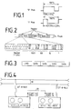
- Fig. 1 is a 100% designated, in the VHS standard for the 625 line / 50Hz / PAL television transmission method 40 msec comprehensive time window from a positive edge (corresponding to approximately a north / south magnetization transition) to the next positive edge shown. If the negative flank occurring between the two positive flanks (corresponding to a south / north magnetization transition) is in the range 60% ⁇ 5% (FIG. 1a), the digital value "0" is thereby coded, the negative flank is located Flank, however, in the range of 27.5% ⁇ 2.5% (Fig. 1b), so that the digital value "1" is encoded.
- FIG. 2 schematically shows how an address code recorded on the control track of a VHS magnetic tape is structured.
- Such an address code consists of four headers, each consisting of eleven bits.
- a data word is inserted between two headers, each of these data words consisting of four BCD digits, which in turn consist of four bits.
- the headers are structured as follows: a first bit "0" is followed by nine bits "1", then a bit "0".
- a header thus consists of a total of eleven bits.
- the position of the four BCD digits is defined according to the recording direction as thousands, hundreds, tens or ones.
- the initial "0" of the first header in the recording direction serves as the reference position.
- FIG. 3 shows an infrared transmission format for transmitting an address contained on the control track.
- this address consists of four BCD digits, so that the number range from 0000 to 9999 is available.
- each of these digits is symbolically labeled "DATA", but they can nevertheless have different values.
- a command word CMD presented to the BCD digits provides information about what type of data is being sent or received.
- Transmitter ICs from Mitsubishi Electric Corporation, 2-3 marunouchi, Tokyo, Japan, for example, can be used as integrated circuits for transmitters for such an infrared transmission link, which generate a format corresponding to the transmission format shown in FIG. 3 M 50467 serve.
- FIG. 4 shows an exemplary embodiment of a device according to the invention for carrying out the copying method in a block diagram.
- a first video recorder VCR1 is in playback mode
- a second video recorder VCR2 is in recording mode.
- the two recorders VCR1, VCR2 are connected to one another via a line 20, which can be a SCART or a video line.
- This line 20 transmits image and sound from one (VCR1) to another (VCR2) video recorder in a conventional manner.
- the video recorders VCR1, VCR2 are also both connected to a D2B bus 30, via which they can exchange data and commands with one another in accordance with the standard defined by the IEC.
- first recorder VCR 1 digital data, such as VISS or VASS marks, corresponding to a control / recording head ("CTL head") assigned to the control track and a coding / decoding electronics belonging to it when playing the tape on the control track Data, recognized, for example, these are transmitted via the D2B bus 30 to the second video recorder VCR2, where they are then recorded by means of its CTL head and the coding / decoding electronics assigned to it during the ongoing recording process at the next possible opportunity in digitally coded form with the control track.
- CTL head control / recording head
- the data coded digitally in the control track can also be transmitted in the form of complete data words; this then takes place, for example, according to the infrared transmission format described for FIG. 3.
- Any other data bus can also be used instead of the D2B bus.
- the still free pins of the SCART line 20 can be provided for this.
- the recording / playback head (“CTL" head) 51 of the recorder VCR1 assigned to the control track of the tape 50 reads out the data contained on the control track in the playback mode.
- This data is sent via lines 52 to a so-called servo processor ⁇ P1, which processes the control information contained therein in accordance with the relevant recording standard - here, for example, in accordance with the VHS standard - in accordance with the standard, thereby ensuring, for example, that the video heads of the VCR1 recorder are controlled correctly.
- the data relating to the tape marks also go via a serial interface 53 to a so-called keyboard processor ⁇ P2, which reads and processes the data.
- the keyboard processor ⁇ P2 controls a display unit with which the marks can be displayed, for example as decimal numbers or as alphanumeric characters.
- the storage of tape marks - for example in the recording mode not present here but in the VCR2 video recorder - can be controlled by the keyboard processor ⁇ P2.
- the data relating to the band marks are processed in accordance with the protocol to be transmitted (D2B bus or an otherwise provided bus system).
- the keyboard processor ⁇ P2 also controls the transfer of the codes relating to the band marks to or from a D2B interface via a line 54, which is connected via lines 55 to the D2B bus 30 (FIG. 4).
- the codes are forwarded via this D2B bus 30 to the video recorder VCR2 provided for recording (FIG. 4).
- the video recorder VCR2 they are recorded in the corresponding reverse manner as in the video recorder VCR1 together with the control data generated by the servo processor there by means of the CTL head of the video recorder VCR2 on the control track of the tape intended for the copy.
- the D2B interface and D2B bus are again mentioned above as representative of other suitable bus systems.
- the I2C bus system, RS232 interface connections or the like can be provided for this purpose.
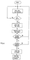
- FIG. 6 shows a flowchart for a program running in the keyboard processor ⁇ P2 using the example of the video recorder VCR1, which is provided here as a playback device. It goes without saying that a correspondingly adapted program is provided for the recording operation, as shown for the video recorder VCR2 in FIG. 4. It is further understood that the VCR1 and VCR2 are preferably set up for both playback and recording modes.
- the data for the transmission protocol are generated and finally output to the D2B bus lines via the D2B interface of the VCR VCR1.
- the program starts again with a jump back to the starting point.
Abstract
Description
Die Erfindung betrifft ein Verfahren zum Kopieren von Magnetbändern, insbesondere von Audio- oder Video- oder Daten-Magnetbändern. Die Erfindung betrifft auch eine Einrichtung zur Durchführung des Verfahrens.The invention relates to a method for copying magnetic tapes, in particular audio or video or data magnetic tapes. The invention also relates to a device for carrying out the method.
Bei herkömmlichen Kopierverfahren werden auf einem bereits bespielten Informationsträger befindliche Nutzinformationen von einem Abspielgerät wiedergegeben, über eine Übertragungsstrecke zu einem Aufzeichnungsgerät weitergeleitet und auf einen zu bespielenden Informationsträger aufgezeichnet. Auf dem zu bespielenden Informationsträger sind im Idealfall nach Abschluß des Überspielvorgangs dieselben Nutzinformationen enthalten wie auf dem Original. Von dem Kopiervorgang nicht betroffen sind etwaige Zusatzinformationen, die bei gewissen Aufzeichnungsstandards - beispielsweise beim VHS-Standard - zur geräteinternen Steuerung des Wiedergabebetriebes zusätzlich zu der eigentlichen Nutzinformation aufgezeichnet werden.In conventional copying methods, useful information located on an already recorded information carrier is reproduced by a playback device, forwarded via a transmission link to a recording device and recorded on an information carrier to be recorded on. Ideally, after the dubbing process has been completed, the same useful information as on the original is contained on the information carrier to be recorded on. Any additional information that is recorded in certain recording standards - for example in the VHS standard - for device-internal control of the playback operation in addition to the actual useful information is not affected by the copying process.
Solche Steuerinformationen werden im Gerät während des Aufzeichnungsvorgangs erzeugt und dienen bei Videorecordern beispielsweise dazu, das Umschalten zwischen mehreren Abtastköpfen einer rotierenden Kopfscheibe bei einem späteren Wiedergeben zu synchronisieren. Die Synchronisationsimpulse werden auf einer Steuer- oder Kontrollspur ("CTL") genannten Längsspur parallel zur Bandkante aufgezeichnet und bestehen im wesentlichen aus scharfen Übergängen von einer Nord- zu einer Süd- bzw. von einer Süd- zu einer Nord-Magnetisierung, wobei es genügt, ständig jeweils zwei aufeinanderfolgende gleichartige Übergänge, beispielsweise von Nord- auf Süd-Magnetisierung, zu betrachten, zwischen denen beim Aufzeichnen beispielsweise eine definierte Zeitspanne von 40 msec verstreicht. Die jeweils anderen Übergänge, im genannten Beispiel also die Übergänge von Süd- auf Nord-Magnetisierung, werden zum Synchronisieren nicht benötigt und können daher in ihrer Relativlage innerhalb des erwähnten 40 msec umfassenden Zeitfensters innerhalb gewisser Grenzen variiert werden, ohne daß hierdurch die ursprüngliche Aufgabe der Synchronisation mittels der Steuerspur zu beeinträchtigt wird.Such control information is generated in the device during the recording process and is used in video recorders, for example, to switch between several scanning heads to synchronize a rotating head disc during later playback. The synchronization pulses are recorded on a control track or control track ("CTL") parallel to the tape edge and consist essentially of sharp transitions from a north to a south or from a south to a north magnetization, whereby it is sufficient to continuously consider two successive transitions of the same type, for example from north to south magnetization, between which, for example, a defined time period of 40 msec elapses during recording. The respective other transitions, i.e. the transitions from south to north magnetization in the example mentioned, are not required for synchronization and can therefore be varied within certain limits within their relative position within the aforementioned 40 msec time window, without the original task of Synchronization by means of the control track is impaired.
Die Variation der Relativlage der Süd-/Nord-Übergänge kann somit beispielsweise zu einer digitalen Codierung verwendet werden. Im VHS-Standard ist hiervon Gebrauch gemacht worden, um auf dem Magnetband magnetische Marken - etwa zum bildgenauen Auffinden bestimmter Stellen einer Aufzeichnung - setzen zu können. Dabei werden zwei Typen von Marken unterschieden, zum einen sogenannte VISS-Marken (VHS-Index-Such-System), die eine unveränderbare digitale Information darstellen, und sogenannte VASS-Marken (VHS-Adress-Such-System), die eine individuelle Adresse in digital codierter Form enthalten.The variation of the relative position of the south / north transitions can thus be used for digital coding, for example. In the VHS standard, use was made of this in order to be able to set magnetic marks on the magnetic tape, for example to locate certain parts of a recording with the exact picture. A distinction is made between two types of brands, the so-called VISS brands (VHS index search system), which represent unchangeable digital information, and the so-called VASS brands (VHS address search system), which represent an individual address included in digitally encoded form.
Insbesondere beim Aufzeichnen von im Verhältnis zur gesamten Bandlänge relativ kurzen Beiträgen als Nutzinformation ist das gleichzeitige Setzen einer Marke beim Starten einer Aufzeichnung zum exakten Auffinden des Anfangs eines solchen Beitrages im Wiedergabebetrieb von Vorteil. Wird nun ein bespieltes Band, das zusätzlich mit solchen Marken versehen ist, jedoch kopiert, so wird dabei bei Kopierverfahren nach dem Stand der Technik lediglich die Nutzinformation, nicht jedoch die Information bezüglich der Marken überspielt, da letztere ja in einem Bereich aufgezeichnet ist, der lediglich für geräteinterne, also vom Benutzer nicht unmittelbar beeinflußbare Steuerzwecke des Wiedergabebetriebes vorgesehen war.In particular when recording contributions which are relatively short in relation to the entire tape length as useful information, the simultaneous setting of a mark when starting a recording is advantageous for precisely locating the start of such a contribution in playback mode. Now becomes a recorded one Tape, which is additionally provided with such marks, but is copied, so in the case of copying methods according to the prior art, only the useful information, but not the information relating to the marks, is transferred, since the latter is recorded in an area which is only for device-internal, control functions of the playback mode that were not directly influenced by the user were provided.
Aus Patent Abstracts of Japan, Vol. 12, No. 220 (P-720) ist ein Verfahren nach dem Oberbegriff des Anspruchs 1 bekannt, bei dem auf der Seite des wiedergebenden Videorecorders eine Integration von durch Tastverhältnisse erhaltenen Spannungen erfolgt. Sofern bei der Integration ein vorbestimmter Schwellpegel überschritten wird, wird an den aufzeichnenden Videorecorder ein die Steuerspur betreffendes Signal abgegeben. Bei dem bekannten Verfahren mit Integration ist es folglich nicht möglich, aus mehreren Bits bestehende, auf der Steuerspur des zu kopierenden Bandes enthaltene Adressen zu überspielen.From Patent Abstracts of Japan, Vol. 12, No. 220 (P-720) a method according to the preamble of
Der Erfindung liegt die Aufgabe zugrunde, beim Kopieren von Magnetbändern eine in einer Steuerspur enthaltene Zusatzinformation beim Kopieren mit zu übertragen.The object of the invention is to transmit additional information contained in a control track when copying magnetic tapes.
Diese Aufgabe wird durch die in Anspruch 1 angegebenen Merkmale gelöst. Diese Aufgabe wird auch durch die in Anspruch 7 angegebenen Merkmale gelöst.This object is achieved by the features specified in
Vorzugsweise geschieht das Aufzeichnen in dem nächsterreichbaren Zeitfenster zugleich mit dem Aufzeichnen der Steuerspur.The recording preferably takes place in the time window that can be accessed at the same time as the recording of the control track.
Das Übertragen der digitalen Information "0" oder "1" kann über eine der sogenannten SCART-Verbindungsleitungen erfolgen, wobei ein Pegel von 0 bzw. 5 Volt den digitalen Informationen "0" bzw. "1" entsprechen kann.The digital information "0" or "1" can be transmitted via one of the so-called SCART connecting lines, wherein a level of 0 or 5 volts can correspond to the digital information "0" or "1".
Es ist vorgesehen, daß zunächst auf der Seite des wiedergebenden Gerätes die digitalen Informationen solange in einem Pufferspeicher zwischengespeichert werden, bis eine aus mehreren Bits bestehende Adresse komplett eingelesen ist; diese komplette Adresse kann sodann über serielle Schnittstellen und eine dazwischen angeordnete Infrarotstrecke an das aufzeichnende Gerät übertragen werden, wo sie dann wieder in einer digital codierten Form mit der Steuerspur aufgezeichnet wird.It is envisaged that the digital information on the reproducing device side in one Buffer memories are buffered until an address consisting of several bits has been completely read in; this complete address can then be transmitted to the recording device via serial interfaces and an infrared path arranged between them, where it is then recorded again in a digitally coded form with the control track.
Es kann ferner vorgesehen sein, eine solche Adresse über einen D2B-Bus von dem wiedergebenden zu dem aufzeichnenden Gerät zu übertragen. Dieser D2B-Bus ist von der Internationalen Elektrotechnischen Kommission (IEC) in einer mit "Projekt Nr. 84.12.05001" bezeichneten Druckschrift (Ausgabe Juni 1988) spezifiziert worden. Bei der Übertragung von Index- oder Adress-Daten kann ein serielles Übertragen, also Bit für Bit, vorgesehen sein. Es kann aber auch vorgesehen sein, den D2B-Bus zu einer Übertragung der Daten gemäß dem vorerwähnten Infrarot-Übertragungsformat zu benutzten. Letzteres bietet gegenüber einer fortlaufenden seriellen Übertragung den Vorteil, daß es den Bus nur kurzzeitig belastet und ist daher einer fortlaufenden seriellen Übertragung vorzuziehen.It can also be provided to transmit such an address from the reproducing device to the recording device via a D2B bus. This D2B bus has been specified by the International Electrotechnical Commission (IEC) in a document entitled "Project No. 84.12.05001" (June 1988 edition). When index or address data is transmitted, serial transmission, that is to say bit by bit, can be provided. However, it can also be provided that the D2B bus is used to transmit the data in accordance with the aforementioned infrared transmission format. The latter has the advantage over continuous serial transmission that it only loads the bus for a short time and is therefore preferable to continuous serial transmission.
Es versteht sich, daß anstelle des D2B-Busses auch jede andere Datenbusverbindung verwendet werden kann.It goes without saying that any other data bus connection can also be used instead of the D2B bus.
Weitere Merkmale, Vorteile und Einzelheiten der Erfindung werden im folgenden an Hand der Zeichnung erläutert. Dabei zeigen:
- Fig. 1
- in schematischer Weise eine Darstellung einer für eine Steuerspur eines VHS-Videorecorders verwendbare digitale Codierung,
- Fig. 2
- den Aufbau eines Adresse-Codes,
- Fig. 3
- eine schematische Darstellung eines Infrarot-Übertragungsformates,
- Fig. 4
- in einem Blockschaltbild ein Ausführungsbeispiel einer erfindungsgemäßen Einrichtung zur Durchführung des Kopierverfahrens,
- Fig. 5
- eine Einzelheit der Einrichtung in Fig. 4 und
- Fig. 6
- ein Flußdiagramm für den Programmablauf in der in Fig. 5 dargestellten Einzelheit.
- Fig. 1
- a schematic representation of a digital coding that can be used for a control track of a VHS video recorder,
- Fig. 2
- the construction of an address code,
- Fig. 3
- a schematic representation of an infrared transmission format,
- Fig. 4
- an embodiment in a block diagram a device according to the invention for carrying out the copying process,
- Fig. 5
- a detail of the device in Fig. 4 and
- Fig. 6
- a flowchart for the program flow in the detail shown in Fig. 5.
In Fig. 1 ist ein mit 100% bezeichnetes, im VHS-Standard für das 625 Zeilen/50Hz/PAL-Fernsehübertragungsverfahren 40 msec umfassendes Zeitfenster von einer positiven Flanke (entsprechend etwa einem Nord-/Süd-Magnetisierungsübergang) bis zur nächsten positiven Flanke schematisch dargestellt. Befindet sich die zwischen den beiden positiven Flanken auftretende negative Flanke (entsprechend also einem Süd-/Nord-Magnetisierungsübergang) im Bereich 60% ± 5% (Fig. 1a), so wird hierdurch der digitale Wert "0" codiert, befindet sich die negative Flanke hingegen im Bereich von 27,5% ± 2,5% (Fig. 1b), so wird hierdurch der digitale Wert "1" codiert.In Fig. 1 is a 100% designated, in the VHS standard for the 625 line / 50Hz / PAL television transmission method 40 msec comprehensive time window from a positive edge (corresponding to approximately a north / south magnetization transition) to the next positive edge shown. If the negative flank occurring between the two positive flanks (corresponding to a south / north magnetization transition) is in the range 60% ± 5% (FIG. 1a), the digital value "0" is thereby coded, the negative flank is located Flank, however, in the range of 27.5% ± 2.5% (Fig. 1b), so that the digital value "1" is encoded.
In Fig. 2 ist schematisch dargestellt, wie ein auf der Steuerspur eines VHS-Magnetbandes aufgezeichneter Adress-Code aufgebaut ist. Ein solcher Adress-Code besteht aus vier Headern, die jeweils aus elf Bits bestehen. Zwischen je zwei Headern ist ein Datenwort eingefügt, wobei jedes dieser Datenwörter aus vier BCD-Ziffern besteht, die ihrerseits wiederum aus vier Bits bestehen. Die Header sind dabei wie folgt aufgebaut: Einem ersten Bit "0" folgen neun Bits "1", sodann ein Bit "0". Ein Header besteht somit insgesamt aus elf Bits. Für die Datenwörter gilt folgendes: In Aufzeichnungsrichtung der vier eine BCD-Ziffer bildenden Bits wird mit dem höchstwertigen Bit begonnen. Der Stellenwert der vier BCD-Ziffern wird entsprechend der Aufzeichnungsrichtung definiert als Tausender, Hunderter, Zehner bzw. Einer. Als Bezugsposition dient die anfängliche "0" des ersten Headers in Aufzeichnungsrichtung.2 schematically shows how an address code recorded on the control track of a VHS magnetic tape is structured. Such an address code consists of four headers, each consisting of eleven bits. A data word is inserted between two headers, each of these data words consisting of four BCD digits, which in turn consist of four bits. The headers are structured as follows: a first bit "0" is followed by nine bits "1", then a bit "0". A header thus consists of a total of eleven bits. The following applies to the data words: In the recording direction of the four bits forming a BCD number, the most significant bit is started. The position of the four BCD digits is defined according to the recording direction as thousands, hundreds, tens or ones. The initial "0" of the first header in the recording direction serves as the reference position.
In Fig. 3 ist ein Infrarot-Übertragungformat zum Übertragen einer auf der Steuerspur enthaltenen Adresse dargestellt. Diese Adresse besteht, wie zu Fig. 2 beschrieben, aus vier BCD-Ziffern, so daß der Zahlenbereich von 0000 bis 9999 zur Verfügung steht. In Fig. 3 ist jede dieser Ziffern symbolisch mit "DATA" bezeichnet, sie können gleichwohl unterschiedliche Werte annehmen. Ein den BCD-Ziffern vorgestelltes Kommandowort CMD gibt Aufschluß darüber, welche Art von Daten gesendet bzw. empfangen werden. Als integrierte Schaltkreise für Sender zu einer solchen Infrarot-Übertragungsstrecke, die ein dem in Fig. 3 dargestellten Übertragungsformat entsprechendes Format generieren, können beispielsweise die Sender-ICs der Fa. Mitsubishi Electric Corporation, 2 - 3 marunouchi, Tokyo, Japan, mit der Bezeichnung M 50467 dienen.3 shows an infrared transmission format for transmitting an address contained on the control track. As described in relation to FIG. 2, this address consists of four BCD digits, so that the number range from 0000 to 9999 is available. In Fig. 3, each of these digits is symbolically labeled "DATA", but they can nevertheless have different values. A command word CMD presented to the BCD digits provides information about what type of data is being sent or received. Transmitter ICs from Mitsubishi Electric Corporation, 2-3 marunouchi, Tokyo, Japan, for example, can be used as integrated circuits for transmitters for such an infrared transmission link, which generate a format corresponding to the transmission format shown in FIG. 3 M 50467 serve.
In Fig. 4 ist in einem Blockschaltbild ein Ausführungsbeispiel einer erfindungsgemäßen Einrichtung zur Durchführung des Kopierverfahrens gezeigt.4 shows an exemplary embodiment of a device according to the invention for carrying out the copying method in a block diagram.
Ein erster Videorecorder VCR1 befindet sich im Wiedergabebetrieb, ein zweiter Videorecorder VCR2 im Aufzeichnungsbetrieb. Die beiden Recorder VCR1, VCR2 sind über eine Leitung 20, die eine SCART- oder eine Video-Leitung sein kann, miteinander verbunden. Über diese Leitung 20 werden Bild und Ton vom einen (VCR1) zum anderen (VCR2) Videorecorder in herkömmlicher Weise übertragen. Die Videorecorder VCR1, VCR2 sind ferner beide an einen D2B-Bus 30 angeschlossen, über den sie entsprechend dem von der IEC festgelegten Standard miteinander Daten und Befehle austauschen können.A first video recorder VCR1 is in playback mode, a second video recorder VCR2 is in recording mode. The two recorders VCR1, VCR2 are connected to one another via a
Werden im ersten Recorder VCR 1 von einem der Steuerspur zugeordneten Aufnahme-/Wiedergabekopf ("CTL-Kopf") und einer diesem zugehörenden Codier-/Decodierelektronik beim Abspielen des Bandes auf der Steuerspur enthaltene digitale Daten, wie etwa VISS- oder VASS-Marken entsprechende Daten, erkannt, so werden diese beispielsweise über den D2B-Bus 30 an den zweiten Videorecorder VCR2 übertragen, wo sie dann mittels dessen CTL-Kopfes und der diesem zugeordneten Codier-/Decodierelektronik während des laufenden Aufzeichnungsvorganges bei nächstmöglicher Gelegenheit in digital codierter Form mit der Steuerspur aufgezeichnet werden.In the
Das Übertragen der in der Steuerspur digital codierten Daten kann auch in Form kompletter Datenwörter erfolgen; dies geschieht dann beispielsweise nach dem zur Fig. 3 beschriebenen Infrarot-Übertragungsformat.The data coded digitally in the control track can also be transmitted in the form of complete data words; this then takes place, for example, according to the infrared transmission format described for FIG. 3.
Bei dem Übertragungsverfahren ist es zwar unvermeidlich, daß auf der Kopie zwischen der Bild-/Ton-Nutzinformation einerseits und der auf der Kopie aufgezeichneten VISS- bzw. VASS-Marke, verglichen mit dem Original, ein zeitlicher Versatz der betreffenden Marke auftritt. Diese Verzögerung beim Kopieren der Marke ist jedoch relativ geringfügig. Je nach Übertragungsweise sowie Besetzt- oder Freisein der Übertragungsstrekke kann dieser Versatz größenordnungsmäßig etwa im Bereich einer Sekunde bzw. von ein paar Sekunden liegen.In the transmission method, it is inevitable that the copy between the video / sound useful information on the one hand and the VISS or VASS mark recorded on the copy, compared to the original, has a time offset of the mark in question. However, this delay in copying the mark is relatively slight. Depending on the type of transmission and whether the transmission path is busy or free, this offset can be of the order of magnitude of approximately one second or a few seconds.
Verglichen mit herkömmlichen Kopierverfahren, bei denen ja solche Marken nicht mit übertragen werden können, sondern mühsam die betreffende Stelle auf der Kopie erst aufgesucht und dann eine Marke manuell über eine Tastatur in die Kopie eingefügt werden muß, kann ein solcher geringfügiger zeitlicher Versatz ohne weiteres in Kauf genommen werden. Sollte der Versatz gleichwohl in Ausnahmefällen als störend betrachtet werden, so kann vorgesehen sein, in einem die Steuerspur der Kopie betreffenden Wiedergabebetrieb die Marken automatisch aufzusuchen und entsprechend einem vorbestimmten oder eingebbaren zeitlichen Betrag auf der Steuerspur versetzt erneut aufzuzeichnen. Dabei kann es genügen, daß die jeweils "alte" Marke lediglich überschrieben wird, ohne daß sie gesondert gelöscht zu werden braucht.Compared to conventional copying methods, in which such marks cannot be transferred, but instead the relevant position on the copy has to be found with difficulty and then a mark has to be inserted into the copy manually via a keyboard, such a slight time offset can easily be found in Purchase. Should the offset nevertheless be regarded as disturbing in exceptional cases, provision can be made to automatically search for the marks in a playback operation relating to the control track of the copy and to record them again on the control track offset according to a predetermined or enterable amount of time. It may be sufficient that each "old" brand is simply overwritten without it having to be deleted separately.
Anstelle des D2B-Busses kann auch jeder andere Datenbus Verwendung finden. Beispielsweise können hierfür die noch freien Pins der SCART-Leitung 20 vorgesehen sein.Any other data bus can also be used instead of the D2B bus. For example, the still free pins of the
In Fig. 5 ist am Beispiel des für die Wiedergabe vorgesehenen Videorecorders VCR1 aus Fig. 4 gezeigt, auf welchem Weg die in der Steuerspur des zu kopierenden Bandes 50 enthaltenen Daten, wie etwa die VISS- oder VASS-Marken entsprechenden Daten, gelesen und gegebenenfalls verarbeitet und weitergeleitet werden können.5, using the example of the video recorder VCR1 from FIG. 4 intended for playback, shows the way in which the data contained in the control track of the
Der der Steuerspur des Bandes 50 zugeordnete Aufnahme-/Wiedergabekopf ("CTL"-Kopf) 51 des Recorders VCR1 liest im Wiedergabebetrieb die auf der Steuerspur enthaltenen Daten aus. Diese Daten gelangen über Leitungen 52 zu einem sogenannten Servoprozessor µP1, der die darin gemäß der betreffenden Aufzeichnungsnorm - hier etwa gemäß der VHS-Norm - enthaltenen Steuerinformationen normgerecht weiterverarbeitet, wodurch beispielsweise die spurgerechte Ansteuerung der Videoköpfe des Recorders VCR1 sichergestellt wird. Von dem Servoprozessor µP1 gelangen ferner die die Bandmarken betreffenden Daten über eine serielle Schnittstelle 53 zu einem sogenannten Keyboardprozessor µP2, der die Daten liest und aufbereitet.The recording / playback head ("CTL" head) 51 of the recorder VCR1 assigned to the control track of the
Der Keyboardprozessor µP2 steuert beispielweise eine Anzeigeeinheit an, mit der die Marken - etwa als Dezimalzahlen oder als alphanumerische Zeichen - angezeigt werden können. Auch das Abspeichern von Bandmarken - beispielsweise im nicht hier sondern bei dem Videorecorder VCR2 vorliegenden - Aufzeichnungsbetrieb kann durch den Keyboardprozessor µP2 gesteuert werden. Im Keyboardprozessor µP2 werden ferner die die Bandmarken betreffenden Daten nach dem zu übertragenden Protokoll (D2B-Bus oder ein sonst vorgesehenes Bussystem) aufbereitet.The keyboard processor µP2, for example, controls a display unit with which the marks can be displayed, for example as decimal numbers or as alphanumeric characters. The storage of tape marks - for example in the recording mode not present here but in the VCR2 video recorder - can be controlled by the keyboard processor µP2. In the keyboard processor µP2 the the data relating to the band marks are processed in accordance with the protocol to be transmitted (D2B bus or an otherwise provided bus system).
Der Keyboardprozessor µP2 steuert schließlich auch den Transfer der die Bandmarken betreffenden Codes zu bzw. von einem D2B-Interface über eine Leitung 54, das über Leitungen 55 an den D2B-Bus 30 (Fig. 4) angeschlossen ist.Finally, the keyboard processor μP2 also controls the transfer of the codes relating to the band marks to or from a D2B interface via a
Über diesen D2B-Bus 30 werden die Codes zu dem für das Aufzeichnen vorgesehenen Videorecorder VCR2 (Fig. 4) weitergeleitet. In dem Videorecorder VCR2 werden sie - in entsprechend umgekehrter Weise wie bei dem Videorecorder VCR1 - zusammen mit den von dem dortigen Servoprozessor erzeugten Steuerdaten mittels des CTL-Kopfes des Videorecorders VCR2 auf der Steuerspur des für die Kopie vorgesehenen Bandes aufgezeichnet.The codes are forwarded via this
D2B-Interface und D2B-Bus sind vorstehend wiederum stellvertretend für sonstige geeignete Bussysteme genannt. Hierfür können etwa das I2C-Bussystem, RS232-Schnittstellenverbindungen oder dergleichen vorgesehen sein.The D2B interface and D2B bus are again mentioned above as representative of other suitable bus systems. The I2C bus system, RS232 interface connections or the like can be provided for this purpose.
In Fig. 6 ist ein Flußdiagramm für ein in dem Keyboardprozessor µP2 ablaufendes Programm am Beispiel des Videorecorders VCR1 dargestellt, der hier als Wiedergabegerät vorgesehen ist. Es versteht sich, daß für den Aufzeichnungsbetrieb, wie er für den Videorecorder VCR2 in Fig. 4 dargestellt ist, ein entsprechend angepaßtes Programm vorgesehen ist. Es versteht sich ferner, daß die Videorecorder VCR1 und VCR2 vorzugsweise sowohl für Wiedergabe- als auch für Aufzeichnungsbetriebsart eingerichtet sind.6 shows a flowchart for a program running in the keyboard processor μP2 using the example of the video recorder VCR1, which is provided here as a playback device. It goes without saying that a correspondingly adapted program is provided for the recording operation, as shown for the video recorder VCR2 in FIG. 4. It is further understood that the VCR1 and VCR2 are preferably set up for both playback and recording modes.
Am Startpunkt des in Fig. 6 dargestellten Programms wird zunächst der Zustand der Bedientastatur des Videorecorders VCR1 eingelesen. Sodann wird überprüft, ob die vom CTL-Kopf gelesene Spur Daten enthält ("CTL DATA?"), die Bandmarken darstellen. Ist dies nicht der Fall, so erfolgt ein Rücksprung zum Startpunkt. Andernfalls werden diese Daten als Bandmarken gespeichert und auf einer Anzeigeeinheit angezeigt.At the starting point of the program shown in Fig. 6, the state of the keyboard of the video recorder is first VCR1 read. It is then checked whether the track read by the CTL head contains data ("CTL DATA?") Which represent tape marks. If this is not the case, you will be returned to the starting point. Otherwise, this data is stored as tape marks and displayed on a display unit.
Anschließend wird überprüft, ob ein externes Interface - etwa die Anwesenheit eines weiteren Videorecorders signalisierend - über den Busausgang des Videorecorders VCR1 angeschlossen ist. Ist dies nicht der Fall, so findet ein Rücksprung zum Startpunkt statt. Andernfalls wird überprüft, ob eine Übertragungsbetriebsart bezüglich des externen Gerätes gewählt ist ("transfer to External selected?"). Ist dies nicht der Fall, so findet ein Rücksprung zum Startpunkt statt.It is then checked whether an external interface - for example signaling the presence of another video recorder - is connected via the bus output of the video recorder VCR1. If this is not the case, there is a jump back to the starting point. Otherwise it is checked whether a transfer mode is selected with regard to the external device ("transfer to external selected?"). If this is not the case, there is a jump back to the starting point.
Andernfalls werden die Daten für das Übertragungsprotokoll erzeugt und schließlich über das D2B-Interface des Videorecorders VCR1 an die D2B-Busleitungen ausgegeben. Mit einem Rücksprung zum Startpunkt beginnt das Programm von neuem.Otherwise, the data for the transmission protocol are generated and finally output to the D2B bus lines via the D2B interface of the VCR VCR1. The program starts again with a jump back to the starting point.
Claims (7)
- Method for copying magnetic tapes, in particular, audio- or video- or data- magnetic tapes, wherein additional items of digital information contained in a control track of the tape which is being copied (50) that are detected when copying the magnetic tapes from a first, reproducing tape device (VCR1), are transmitted via a transmission path (20; 30) to a second, recording tape device (VCR2) and are recorded there in a digitally coded form onto the control track during a corresponding time window, characterised in that, initially, at the reproducing device end, the items of digital information are intermediately stored in a buffer store for a length of time sufficient for an address consisting of a plurality of bits to be completely written in, that thereafter this address is completely transmitted via serial interfaces (D²B-interfaces) to the recording device (VCR2) where it is then re-recorded in a digitally coded form by the control track.
- Method in accordance with Claim 1, characterised in that, if necessary, the transmission of the address takes place via an infra-red path arranged between the serial interfaces (D²B-interfaces).
- Method in accordance with Claim 1 or 2, characterised in that, this recording takes place in the next attainable time window conjointly with the recording of the control track.
- Method in accordance with any of the preceding Claims, characterised in that, the transmission of an item of digital information "0" or "1" takes place via so-called Scart-connecting cables (20).
- Method in accordance with Claim 4, characterised in that, the level of approximately 0 or approximately 5 volt corresponds to the items of digital information "0" or "1".
- Method in accordance with any of the preceding Claims, Claims, characterised in that, an address is transmitted from the reproducing (VCR1) to the recording device (VCR2) via a D2B-bus (30).
- Apparatus for copying magnetic tapes, in particular, audio- or video- or data- magnetic tapes, wherein additional items of digital information contained in a control track of the tape which is being copied (50) that are detected when copying the magnetic tapes from a first, reproducing tape device (VCR1), are transmitted via a transmission path (20; 30) to a second recording tape device (VCR2) and are recorded there in a digitally coded form onto the control track during a corresponding time window, characterised in that, at the reproducing device end, there is provided a buffer store in which the items of digital information are initially intermediately stored for a length of time sufficient for an address consisting of a plurality of bits to be completely written in, and that serial interfaces (D²B-interfaces) are provided via which this address is thereafter completely transmitted to the recording device (VCR2) where it is then re-recorded in a digitally coded form by the control track.
Priority Applications (1)
| Application Number | Priority Date | Filing Date | Title |
|---|---|---|---|
| AT90912108T ATE99075T1 (en) | 1989-08-25 | 1990-08-18 | METHOD AND APPARATUS FOR COPYING MAGNETIC TAPE. |
Applications Claiming Priority (4)
| Application Number | Priority Date | Filing Date | Title |
|---|---|---|---|
| DE3928190 | 1989-08-25 | ||
| DE3928190 | 1989-08-25 | ||
| DE3932059 | 1989-08-26 | ||
| DE3932059A DE3932059A1 (en) | 1989-08-25 | 1989-08-26 | METHOD AND DEVICE FOR COPYING MAGNETIC BANDS |
Publications (2)
| Publication Number | Publication Date |
|---|---|
| EP0489040A1 EP0489040A1 (en) | 1992-06-10 |
| EP0489040B1 true EP0489040B1 (en) | 1993-12-22 |
Family
ID=25884432
Family Applications (1)
| Application Number | Title | Priority Date | Filing Date |
|---|---|---|---|
| EP90912108A Expired - Lifetime EP0489040B1 (en) | 1989-08-25 | 1990-08-18 | Process and device for copying magnetic tapes |
Country Status (12)
| Country | Link |
|---|---|
| EP (1) | EP0489040B1 (en) |
| JP (1) | JPH05500725A (en) |
| KR (1) | KR0158439B1 (en) |
| CN (1) | CN1028573C (en) |
| AT (1) | ATE99075T1 (en) |
| AU (1) | AU6172090A (en) |
| DE (2) | DE3932059A1 (en) |
| ES (1) | ES2048500T3 (en) |
| HK (1) | HK8596A (en) |
| HU (1) | HUT63266A (en) |
| MY (1) | MY106452A (en) |
| WO (1) | WO1991003044A1 (en) |
Families Citing this family (2)
| Publication number | Priority date | Publication date | Assignee | Title |
|---|---|---|---|---|
| GB9219709D0 (en) * | 1992-09-17 | 1992-10-28 | D2B Systems Co Ltd | Apparatus interconnected for the communication of control messages |
| MY122982A (en) * | 1994-12-22 | 2006-05-31 | Sony Corp | Recording medium and apparatus for protecting copyrighted digital data |
Family Cites Families (1)
| Publication number | Priority date | Publication date | Assignee | Title |
|---|---|---|---|---|
| JPS5897737U (en) * | 1981-12-22 | 1983-07-02 | 日本ビクター株式会社 | magnetic recording and reproducing device |
-
1989
- 1989-08-26 DE DE3932059A patent/DE3932059A1/en not_active Withdrawn
-
1990
- 1990-08-18 KR KR1019920700421A patent/KR0158439B1/en not_active IP Right Cessation
- 1990-08-18 AT AT90912108T patent/ATE99075T1/en not_active IP Right Cessation
- 1990-08-18 DE DE90912108T patent/DE59003978D1/en not_active Expired - Fee Related
- 1990-08-18 EP EP90912108A patent/EP0489040B1/en not_active Expired - Lifetime
- 1990-08-18 HU HU92593A patent/HUT63266A/en unknown
- 1990-08-18 AU AU61720/90A patent/AU6172090A/en not_active Abandoned
- 1990-08-18 JP JP2511588A patent/JPH05500725A/en active Pending
- 1990-08-18 ES ES90912108T patent/ES2048500T3/en not_active Expired - Lifetime
- 1990-08-18 WO PCT/EP1990/001360 patent/WO1991003044A1/en active IP Right Grant
- 1990-08-24 MY MYPI90001457A patent/MY106452A/en unknown
- 1990-08-25 CN CN90108177A patent/CN1028573C/en not_active Expired - Fee Related
-
1996
- 1996-01-18 HK HK8596A patent/HK8596A/en not_active IP Right Cessation
Non-Patent Citations (2)
| Title |
|---|
| Patent Abstracts of Japan, vol. 10, no. 259, E-434 abstract from JP-61 84180, publ. 1986-04-28 * |
| Patent Abstracts of Japan, vol. 12, no. 220, P-720, abstract from JP-63-14389, publ. 1988-01-21 * |
Also Published As
| Publication number | Publication date |
|---|---|
| HU9200593D0 (en) | 1992-05-28 |
| JPH05500725A (en) | 1993-02-12 |
| KR0158439B1 (en) | 1999-01-15 |
| CN1028573C (en) | 1995-05-24 |
| MY106452A (en) | 1995-05-30 |
| ES2048500T3 (en) | 1994-03-16 |
| DE59003978D1 (en) | 1994-02-03 |
| ATE99075T1 (en) | 1994-01-15 |
| KR920704275A (en) | 1992-12-19 |
| CN1050455A (en) | 1991-04-03 |
| WO1991003044A1 (en) | 1991-03-07 |
| HUT63266A (en) | 1993-07-28 |
| DE3932059A1 (en) | 1991-02-28 |
| AU6172090A (en) | 1991-04-03 |
| EP0489040A1 (en) | 1992-06-10 |
| HK8596A (en) | 1996-01-26 |
Similar Documents
| Publication | Publication Date | Title |
|---|---|---|
| EP0363653B1 (en) | Method for recording and reproducing the table of contents of a magnetic-tape video cassette, and video recorder for carrying out the method | |
| EP0424653B1 (en) | Videorecorder comprising a device for storing the table of contents of a cassettemagazine containing a plurality of magnetic tape cassettes | |
| DE19513952C2 (en) | Voice information transmission system | |
| DE2205893A1 (en) | Method and device for the automatic assembly of television information | |
| EP0090292A2 (en) | Combination of entertainment electronics devices including a television receiver, a video recorder and/or a playback apparatus | |
| DE3621263A1 (en) | Recording and reproducing apparatus with a recording carrier | |
| EP0029946A1 (en) | Arrangement for storing and relocating positions on record carriers in tape form in a recording and/or reproducing apparatus | |
| DE3016059A1 (en) | TAPE DETECTOR FOR A PCM RECORDING AND PLAYBACK DEVICE | |
| EP0489040B1 (en) | Process and device for copying magnetic tapes | |
| DE2132240A1 (en) | COMPUTER-CONTROLLED TEACHING SYSTEM | |
| DE3827970C2 (en) | ||
| DE4301441A1 (en) | ||
| EP0362561B1 (en) | Method of, and video magnetic tape recorder for avoiding the inadvertent overwriting of video signal parts recorded on a video magnetic tape | |
| DE3011810A1 (en) | METHOD AND DEVICE FOR FINDING A STORAGE SPACE ON A RECORDING CARRIER | |
| DE3705353A1 (en) | AUTOMATIC CUEING DEVICE | |
| DE3401421A1 (en) | ADDRESS DATA TRANSFER DEVICE | |
| EP0344626A1 (en) | System for reproducing video records from a magnetic video tape recorder | |
| DE3008190A1 (en) | Cutting and assembling video and/or audio recording carrier - using off=line marker programming kit with keyboard and display | |
| EP1252626B1 (en) | Playback device for compressed audio data | |
| EP0503519B1 (en) | Videorecorder with memory to store the table of contents of a plurality of magnetic cassettes | |
| EP0277549A2 (en) | Recorder | |
| DE3742468C1 (en) | Video recording device with a desired program memory | |
| DE4312922B4 (en) | Recording device and playback device | |
| EP0401476B1 (en) | Video tape recorder with an arrangement for electronic editing of picture signals in skewed tracks of a magnetic tape with recorded picture and fm-sound signals | |
| DD297273A5 (en) | METHOD AND DEVICE FOR COPYING MAGNETIC TRANSMITTERS |
Legal Events
| Date | Code | Title | Description |
|---|---|---|---|
| PUAI | Public reference made under article 153(3) epc to a published international application that has entered the european phase |
Free format text: ORIGINAL CODE: 0009012 |
|
| 17P | Request for examination filed |
Effective date: 19920220 |
|
| AK | Designated contracting states |
Kind code of ref document: A1 Designated state(s): AT BE CH DE DK ES FR GB IT LI LU NL SE |
|
| 17Q | First examination report despatched |
Effective date: 19920708 |
|
| GRAA | (expected) grant |
Free format text: ORIGINAL CODE: 0009210 |
|
| STAA | Information on the status of an ep patent application or granted ep patent |
Free format text: STATUS: THE PATENT HAS BEEN GRANTED |
|
| ITF | It: translation for a ep patent filed |
Owner name: BARZANO' E ZANARDO MILA |
|
| AK | Designated contracting states |
Kind code of ref document: B1 Designated state(s): AT BE CH DE DK ES FR GB IT LI LU NL SE |
|
| PG25 | Lapsed in a contracting state [announced via postgrant information from national office to epo] |
Ref country code: SE Effective date: 19931222 Ref country code: NL Effective date: 19931222 Ref country code: DK Effective date: 19931222 Ref country code: BE Effective date: 19931222 |
|
| REF | Corresponds to: |
Ref document number: 99075 Country of ref document: AT Date of ref document: 19940115 Kind code of ref document: T |
|
| GBT | Gb: translation of ep patent filed (gb section 77(6)(a)/1977) |
Effective date: 19940105 |
|
| REF | Corresponds to: |
Ref document number: 59003978 Country of ref document: DE Date of ref document: 19940203 |
|
| REG | Reference to a national code |
Ref country code: ES Ref legal event code: FG2A Ref document number: 2048500 Country of ref document: ES Kind code of ref document: T3 |
|
| ET | Fr: translation filed | ||
| NLV1 | Nl: lapsed or annulled due to failure to fulfill the requirements of art. 29p and 29m of the patents act | ||
| PG25 | Lapsed in a contracting state [announced via postgrant information from national office to epo] |
Ref country code: AT Effective date: 19940818 |
|
| PG25 | Lapsed in a contracting state [announced via postgrant information from national office to epo] |
Ref country code: LU Free format text: LAPSE BECAUSE OF NON-PAYMENT OF DUE FEES Effective date: 19940831 Ref country code: LI Effective date: 19940831 Ref country code: CH Effective date: 19940831 |
|
| PLBE | No opposition filed within time limit |
Free format text: ORIGINAL CODE: 0009261 |
|
| 26N | No opposition filed | ||
| REG | Reference to a national code |
Ref country code: CH Ref legal event code: PL |
|
| PGFP | Annual fee paid to national office [announced via postgrant information from national office to epo] |
Ref country code: GB Payment date: 19980703 Year of fee payment: 9 |
|
| PGFP | Annual fee paid to national office [announced via postgrant information from national office to epo] |
Ref country code: FR Payment date: 19980814 Year of fee payment: 9 |
|
| PGFP | Annual fee paid to national office [announced via postgrant information from national office to epo] |
Ref country code: ES Payment date: 19980828 Year of fee payment: 9 Ref country code: DE Payment date: 19980828 Year of fee payment: 9 |
|
| PG25 | Lapsed in a contracting state [announced via postgrant information from national office to epo] |
Ref country code: GB Free format text: LAPSE BECAUSE OF NON-PAYMENT OF DUE FEES Effective date: 19990818 |
|
| PG25 | Lapsed in a contracting state [announced via postgrant information from national office to epo] |
Ref country code: ES Free format text: LAPSE BECAUSE OF NON-PAYMENT OF DUE FEES Effective date: 19990819 |
|
| GBPC | Gb: european patent ceased through non-payment of renewal fee |
Effective date: 19990818 |
|
| PG25 | Lapsed in a contracting state [announced via postgrant information from national office to epo] |
Ref country code: FR Free format text: LAPSE BECAUSE OF NON-PAYMENT OF DUE FEES Effective date: 20000428 |
|
| PG25 | Lapsed in a contracting state [announced via postgrant information from national office to epo] |
Ref country code: DE Free format text: LAPSE BECAUSE OF NON-PAYMENT OF DUE FEES Effective date: 20000601 |
|
| REG | Reference to a national code |
Ref country code: FR Ref legal event code: ST |
|
| REG | Reference to a national code |
Ref country code: ES Ref legal event code: FD2A Effective date: 20000911 |
|
| PG25 | Lapsed in a contracting state [announced via postgrant information from national office to epo] |
Ref country code: IT Free format text: LAPSE BECAUSE OF NON-PAYMENT OF DUE FEES;WARNING: LAPSES OF ITALIAN PATENTS WITH EFFECTIVE DATE BEFORE 2007 MAY HAVE OCCURRED AT ANY TIME BEFORE 2007. THE CORRECT EFFECTIVE DATE MAY BE DIFFERENT FROM THE ONE RECORDED. Effective date: 20050818 |