EP0488795B1 - Bewegungsvektorerfassungsgerät - Google Patents
Bewegungsvektorerfassungsgerät Download PDFInfo
- Publication number
- EP0488795B1 EP0488795B1 EP19910311131 EP91311131A EP0488795B1 EP 0488795 B1 EP0488795 B1 EP 0488795B1 EP 19910311131 EP19910311131 EP 19910311131 EP 91311131 A EP91311131 A EP 91311131A EP 0488795 B1 EP0488795 B1 EP 0488795B1
- Authority
- EP
- European Patent Office
- Prior art keywords
- block
- blocks
- motion vector
- picture elements
- picture
- Prior art date
- Legal status (The legal status is an assumption and is not a legal conclusion. Google has not performed a legal analysis and makes no representation as to the accuracy of the status listed.)
- Expired - Lifetime
Links
Images


Classifications
-
- H—ELECTRICITY
- H04—ELECTRIC COMMUNICATION TECHNIQUE
- H04N—PICTORIAL COMMUNICATION, e.g. TELEVISION
- H04N19/00—Methods or arrangements for coding, decoding, compressing or decompressing digital video signals
- H04N19/50—Methods or arrangements for coding, decoding, compressing or decompressing digital video signals using predictive coding
-
- H—ELECTRICITY
- H04—ELECTRIC COMMUNICATION TECHNIQUE
- H04N—PICTORIAL COMMUNICATION, e.g. TELEVISION
- H04N5/00—Details of television systems
- H04N5/14—Picture signal circuitry for video frequency region
- H04N5/144—Movement detection
- H04N5/145—Movement estimation
-
- G—PHYSICS
- G06—COMPUTING OR CALCULATING; COUNTING
- G06T—IMAGE DATA PROCESSING OR GENERATION, IN GENERAL
- G06T7/00—Image analysis
- G06T7/20—Analysis of motion
- G06T7/223—Analysis of motion using block-matching
- G06T7/231—Analysis of motion using block-matching using full search
-
- H—ELECTRICITY
- H04—ELECTRIC COMMUNICATION TECHNIQUE
- H04N—PICTORIAL COMMUNICATION, e.g. TELEVISION
- H04N11/00—Colour television systems
- H04N11/04—Colour television systems using pulse code modulation
-
- H—ELECTRICITY
- H04—ELECTRIC COMMUNICATION TECHNIQUE
- H04N—PICTORIAL COMMUNICATION, e.g. TELEVISION
- H04N19/00—Methods or arrangements for coding, decoding, compressing or decompressing digital video signals
- H04N19/42—Methods or arrangements for coding, decoding, compressing or decompressing digital video signals characterised by implementation details or hardware specially adapted for video compression or decompression, e.g. dedicated software implementation
-
- H—ELECTRICITY
- H04—ELECTRIC COMMUNICATION TECHNIQUE
- H04N—PICTORIAL COMMUNICATION, e.g. TELEVISION
- H04N19/00—Methods or arrangements for coding, decoding, compressing or decompressing digital video signals
- H04N19/50—Methods or arrangements for coding, decoding, compressing or decompressing digital video signals using predictive coding
- H04N19/503—Methods or arrangements for coding, decoding, compressing or decompressing digital video signals using predictive coding involving temporal prediction
- H04N19/51—Motion estimation or motion compensation
-
- H—ELECTRICITY
- H04—ELECTRIC COMMUNICATION TECHNIQUE
- H04N—PICTORIAL COMMUNICATION, e.g. TELEVISION
- H04N19/00—Methods or arrangements for coding, decoding, compressing or decompressing digital video signals
- H04N19/60—Methods or arrangements for coding, decoding, compressing or decompressing digital video signals using transform coding
- H04N19/61—Methods or arrangements for coding, decoding, compressing or decompressing digital video signals using transform coding in combination with predictive coding
-
- H—ELECTRICITY
- H04—ELECTRIC COMMUNICATION TECHNIQUE
- H04N—PICTORIAL COMMUNICATION, e.g. TELEVISION
- H04N19/00—Methods or arrangements for coding, decoding, compressing or decompressing digital video signals
- H04N19/90—Methods or arrangements for coding, decoding, compressing or decompressing digital video signals using coding techniques not provided for in groups H04N19/10-H04N19/85, e.g. fractals
- H04N19/96—Tree coding, e.g. quad-tree coding
-
- G—PHYSICS
- G06—COMPUTING OR CALCULATING; COUNTING
- G06T—IMAGE DATA PROCESSING OR GENERATION, IN GENERAL
- G06T2200/00—Indexing scheme for image data processing or generation, in general
- G06T2200/28—Indexing scheme for image data processing or generation, in general involving image processing hardware
-
- G—PHYSICS
- G06—COMPUTING OR CALCULATING; COUNTING
- G06T—IMAGE DATA PROCESSING OR GENERATION, IN GENERAL
- G06T2207/00—Indexing scheme for image analysis or image enhancement
- G06T2207/10—Image acquisition modality
- G06T2207/10016—Video; Image sequence
-
- G—PHYSICS
- G06—COMPUTING OR CALCULATING; COUNTING
- G06T—IMAGE DATA PROCESSING OR GENERATION, IN GENERAL
- G06T2207/00—Indexing scheme for image analysis or image enhancement
- G06T2207/20—Special algorithmic details
- G06T2207/20048—Transform domain processing
- G06T2207/20052—Discrete cosine transform [DCT]
Definitions
- This invention relates to motion vector detection apparatus and to band compression apparatus providing a combination of motion compensation and inter-frame encoding.
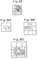
- Figures 3A to 3C of the accompanying drawings show positional relationships between such a block where a picture element C is the centre picture element and another block where a picture element C' is the centre picture element.
- the former block is from a current frame
- the latter block is from a preceding frame and matches the picture content of the block of the current frame but, due to motion, is at a position in the preceding frame with a centre picture element C'.
- Figure 3A thus represents a motion vector where the centre position of the picture has moved by +1 picture element in the horizontal direction and by +1 line in the vertical direction.
- Figure 3B represents a motion vector where the centre position of the picture has moved by +3 picture elements in the horizontal direction and by +3 lines in the vertical direction.
- Figure 3C represents a motion vector where the centre position of the picture has moved by +2 picture elements in the horizontal direction and by -1 line in the vertical direction.
- a motion vector can be obtained for each block of the current frame.
- a particular block of the current frame should be compared with various blocks in the preceding frame where C' is moved from C, which is the centre of the current frame, over ⁇ S picture elements in the horizontal direction and over ⁇ T lines in the vertical direction.
- Figure 4 of the accompanying drawings indicates that, when the position of the centre picture element C of a particular block of the current frame is R, it should be compared with (2S + 1) x (2T + 1) blocks of the preceding frame. In other words, all blocks of the preceding frame where C' is present, as shown in Figure 4, should be compared.
- some of the blocks may be omitted in detecting a motion vector.
- all positional relationships are compared over ⁇ S picture elements in the horizontal direction and ⁇ T lines in the vertical direction, some combinations of these comparisons may in fact be omitted. Nevertheless, in the following, all combinations are compared so as to simplify the description.
- Figure 6 is a conceptual block diagram of a system or structure for detecting a motion vector.
- Data a which is supplied from an input terminal 101, is picture data of a current frame.
- Data b is picture data of a just preceding frame which is delayed for one frame by a frame memory 102.
- a delay portion 103 causes the data b of the preceding frame to become data with various positional relationships as shown in Figure 3.
- the data is compared with the data a for the various positional relationships.
- a block comparison portion 104 outputs a matching ratio or degree of the picture for each deviated position.
- a determination portion 105 compares the matching ratios and outputs a most suitable deviation amount, namely a motion vector, to an output terminal 106.
- the hardware for detecting the motion vector shown in Figure 6 requires large capacity memories for the delay portion 103 and the block comparison portion 104, together with the frame memory 102. When some of the comparisons are not omitted, the size of a calculation portion of the block comparison portion 104 becomes large. In addition, the size of the determination portion 105 also becomes large, depending on the method of omitting comparisons. Thus, the hardware for detecting the motion vector takes up a large part of a system which employs the detection of motion vectors.
- Embodiments of the invention described below seek to decrease the amount of hardware for the delay portion 103 and the block comparison portion 104, except for the determination portion 105 shown in Figure 6, and in particular seek to decrease the amount of hardware for the delay portion 103.
- Figures 7 and 8 show a first previously proposed system.
- Figure 7 shows portions equivalent to the frame memory 102 and the delay portion 103 shown in Figure 6.
- a circuit F is the frame memory 102 for delaying input data by one frame
- circuits H are delay circuits for effecting a delay of one horizontal scanning line
- small circuit blocks without reference signs are delay circuits for effecting a delay of one picture element, namely registers
- circuits (H - 9) are delay circuits for delaying picture elements by one line less 9 picture elements.
- one line is delayed by one line interval by a delay of (H - 9) plus nine delays of one positive element each (registers).
- the input data a of the current frame is delayed for 3 lines and 5 picture elements by a delay circuit 107 (shown with its constituent elements surrounded by a dotted line) which becomes the centre position R of the block.
- the resultant data is supplied to an output terminal 108.
- the positions of the picture elements of the data a are the same as those of the data b.
- groups of nine stages of registers and one delay circuit (H - 9) are connected in series, and a tap C (0, 0) which has a delay of 3 lines and 5 picture elements relative to the data b has a delay of one frame relative to the centre position R.
- a data sequence which has been horizontally scanned is inputted like a conventional picture signal.
- the tap C (1, 0) data which is older by one picture element in the horizontal direction than C (0, 0) and (R) is obtained.
- the data of the picture element to the left of R on the display screen shown in Figure 4 is obtained.
- a motion vector is obtained, by using each tap shown in Figure 7, by performing the following process.
- data at each deviated position as shown in Figure 4 is obtained.
- the block comparison portion 104 compares each tap with R, calculates the degree of matching (of two pictures), and obtains a result for each value of (i, j). Thereafter, the determination portion 105 examines the results and selects a proper motion vector (i, j). (In a particular situation, i and j may be determined with real numbers rather than integer numbers.)
- blocks are compared for each tap C (i, j), as shown in Figure 3. From R, each picture element of the block at the centre portion shown in Figure 5 is obtained. On the other hand, from the tap C (i, j), each picture element of the block of the preceding frame which deviates by i picture elements in the horizontal direction and by j lines in the vertical direction is obtained. A subtraction circuit 109 obtains the difference between each corresponding position of the two blocks. As absolute value calculation circuit 110 calculates the absolute value (ABS) of the difference. An addition circuit 111 and a memory 112 accumulate the difference for all picture elements making up one block, namely for P x Q elements. The accumulated output is the degree of matching for (i, j).
- ABS absolute value
- each picture element according to blocks in the combinations shown in Figure 3 should be obtained in succession.
- each picture element of the first line of the block is inputted to R and C (i, j).
- data for comparing the adjacent block, rather than each picture element of the next line is inputted to R and C (i, j).
- each picture element of the second line of the former block is compared.
- the memory 112 for storing H/P words or more is arranged to be an accumulation memory.
- the circuit of Figure 8 includes an address generation circuit 113 that increments the address by 1 at intervals of P cycles which are equivalent to the number of horizontal picture elements making up one block, and resets the address to "0" after one horizontal scanning is completed.
- the address generation circuit 113 can control a memory address assignment circuit in the manner shown in Figure 9.
- the cumulative operation for matching blocks should be reset at intervals of H/P blocks disposed in the horizontal direction of the screen.
- This reset operation can be performed by setting all values b0 to bn-1 of the memory 112 to "0".
- the number of words that the memory 112 contains becomes one word.
- the number of words that the memory 112 should have depends upon the condition of obtaining motion vectors.
- circuits shown in Figures 7 and 8 can be realised and controlled with relative ease, their sizes are disadvantageously large.
- the frame memory 102 and the calculation circuits shown in Figure 8 are theoretically essential.
- the large number of delay circuits (H - 9) and the memories 112 having H/P words for each cumulative operation are required constructionally, not essentially.
- the delay circuits and the memories are required since input data has been horizontally scanned.
- the memories are required to compare the blocks as shown in Figure 3 in accordance with the input which has been horizontally scanned as shown in Figure 10A.
- a second prior proposal compares blocks in such a manner that an input data sequence a is data which has been scanned for each block as shown in Figure 10B, while a data sequence b with a delay of one frame relative thereto is scanned in a wide area when the block of the data a is at the centre portion shown in Figure 5.
- the amount of data of the former data sequence differs from that of the latter data sequence.
- the number of picture elements of one block to be compared for the data sequence a is (P x Q)
- that for the data sequence b is ⁇ (2S + P) x (2T + Q) ⁇ .
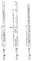
- the clock frequency of the data sequence b is correspondingly increased so that the data sequence a and the data sequence b take place in accordance with timing charts shown in Figures 11A to 11C of the accompanying drawings.
- the data sequence a takes place in accordance with a timing chart as shown in Figure 11A.
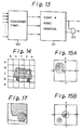
- Figure 12 depicts an arrangement including a scanning transformation circuit 115 for transforming the input data sequence a into a data sequence as shown in Figure 11B.
- a scanning sequence transformation circuit 116 transform a data sequence b from a frame memory 102′ into a data sequence as shown in Figure 11C.
- the data sequence b′ in which the scanning sequence has been transformed is sent to a delay portion which is composed of (2S + 1) x (2T + 1) shift register stages, which are the same as those shown in Figure 7. Thereafter, in the construction shown in Figure 8, blocks are compared.
- the (H - 9) delay circuits used in the first prior proposal ( Figure 7) become unnecessary.
- the number of words that the memory of the accumulator shown in Figure 8 requires becomes one word.
- the frame store 102′ in Figure 12 has a delay (F-32) which is smaller than a frame delay by 32 picture elements.
- the frame memory 102′ sets the timing difference between R and C (0, 0) to one frame.
- the scanning sequence of the television signal is transformed into the scanning sequence for every (P x Q) blocks
- the scanning sequence shown in Figure 10A is transformed into the scanning sequence of every block shown in Figure 10B.
- at least a line memory with the vertical length of the blocks is required. This memory is not small in terms of hardware.
- the scanning operation as shown in Figure 10B is required for various purposes such as for band compression which requires the detection of a motion vector
- the scanning sequence transformation of P x Q as shown in Figure 11A does not always become a burden upon the apparatus.
- the data sequence a′ as shown in Figure 11B and the scanning sequence transformation of (P + 2S) x (Q + 2T) as shown in Figure 11C are not used for other process, they become a burden upon the apparatus.
- the construction of the (P + 2S) x (Q + 2T) shift register stages in the second prior proposal is simpler than that of the (H - 9) delay circuit group in terms of hardware.
- the delay portion of the second prior proposal is simpler than that of the first prior proposal.
- a simple register can be used for the memory of the accumulator.
- the scanning sequence transformations P x Q and (P + 2S) x (Q + 2T) are required.
- more memories than the (H - 9) delay circuit group shown in Figure 7 are required.
- the data rate is increased by (P + 2S) x (Q + 2T)/P x Q times.
- the cumulative operation should be controlled.
- motion vectors which are detected are compensated in various picture processes.
- two frames (or fields) are compared so as to obtain a motion vector, namely a deviation between the pictures. Thereafter, one of the frames (or fields) is moved according to the amount of the deviation so as to overlap both the pictures.
- a motion picture involves not only parallel movement, but also rotation, enlargement, and reduction.
- the parallel movement component is detected and considered in the form of a motion vector.
- a motion vector detection method which has been widely used, a screen is divided into small square blocks and a motion vector is then obtained for each block. With respect to problems in detecting motion vectors and compensating them, the following items should be considered.
- the determination portion 105 comprises a remainder comparison circuit 120, to which a remainder for each deviated position after comparison of blocks is sent, and a comparison and noise removal circuit 121.
- the remainder comparison circuit 120 supplies the position and the amount of the most minimum value of the remainder, the position and amount of the second minimum value of the remainder, and the position and amount of the third minimum value of the remainder, to the comparison and noise removal circuit 121, which removes data which is determined to be noise and compares remainders.
- a determination signal representing the validity of the motion compensation and a motion vector are outputted through an AND gate 123.
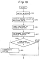
- blocks are matched (in a step 124). Thereafter, the minimum value of the degree of matching is detected (in a step 125).
- the vectors at the minimum position are sorted in the order of matching ratios (in a step 126).
- the significant minimum position (where it is determined that a motion subject of the vector is present) is determined (in a step 127).
- the number of peaks of the minimum position is checked (in a step 128). If the number of peaks is 1, the motion is compensated (in a step 129). Otherwise, the motion is not compensated.
- the minimum value is present at a vector which is such as a background in the panning of a camera or within the contours of a moving subject.
- Figure 15B shows the case of a contour of a moving subject where two minimum values (two vectors) are present.
- contour of the moving subject is for example the block D-b of Figure 14, which block is shown enlarged in Figure 17 of the accompanying drawings.
- the determination portion and motion vector compensation technique as described above are subject to the following disadvantages.
- inter-frame encoding technique using motion compensation has been proposed.
- the inter-frame encoding is used for band compression employed for transmitting a picture signal.
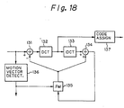
- the encoding method which is a combination of motion compensation and inter-frame differentiation, can be roughly accomplished in a construction as shown in Figure 18 of the accompanying drawings.
- Figure 18 of the accompanying drawings For the theory of operation of the circuitry, refer for example to "Multidimensional Signal Processing of TV Pictures", Nuki Fuki, Nikkan-Kogyo Shinbun, pp 266-280, particularly Figure 7-29 on page 274.
- the arrangement shown in Figure 18 includes a discrete cosine transformation (DCT) circuit 132, an inverse discrete cosine transformation (IDCT) circuit 133, and a frame memory (FM) 135 for delaying a frame.
- Input data is supplied to a motion vector detection circuit 136 and a subtraction circuit 131.
- the subtraction circuit 131 subtracts a locally decoded output of the preceding frame from the input data.
- the local decoding is performed by the IDCT circuit 133 and an addition circuit 134.
- the amount of encoded data which is generated in the DCT circuit 132 is compressed by encoding, such as Huffman encoding, carried out by means of an encoding assignment circuit 137.
- motion compensation of the frame memory 135 is accomplished by a motion vector produced by the motion vector detection circuit 136, which is disposed out of the centre loop shown in Figure 18.
- the motion vector detection circuit 136 requires another frame memory along with the frame memory 135 used for the band compression unit ( Figure 18).
- two frame memories are required for motion vector detection and band compression.
- a motion vector detection apparatus comprising:
- An embodiment of the invention further comprises means responsive to the determination of the presence of an image contour, to segment the blocks of the neighbourhood.
- the determining means comprises transform means for performing a spatial frequency transform of the correlated motion vectors.
- the transform is preferably a Fourier Transform but could be a Hadamand Transform or a Hartley Transform.
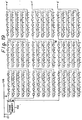
- the taps output picture element in such a manner that the output picture elements of R are vertically and horizontally inverted as the just preceding frame.
- the frame memory 102 is provided with three outputs.
- An output e has a delay ( F - 5H - 50 ) which is less than one frame by 5 H and 50 picture elements.
- An output f has a delay (F - 50) which is less than one frame by 50 picture elements.
- An output g has a delay ( F + 5H - 50 ) which is greater than one frame by 5 H minus 50 picture elements.
- Shift registers are connected to the outputs e, f, and g in such a manner that blocks are scanned. Each of the shift registers has a tap. 50 picture elements are twice as many as P x Q. A tap denoted by d in Figure 14, which is delayed by shift registers for 50 picture elements from the output f, has one frame difference from R.
- circuitry as mentioned before can be connected to each of points e', f', and g' in Figure 19, this is not necessary due to a reason which will be described later.
- the outputs f and g could be obtained by adding delay circuits to the points e' and f', respectively, though in this embodiment they are obtained from the frame memory 102.
- first data of a particular block of the current frame is present at R
- the successive 25 picture elements which are outputted are for this block.
- first data of a block of the preceding frame at the same position as the block of the current frame on the screen is present at d.
- the successive 25 picture elements are data which accord with R in screen positions.
- Figure 20 shows an array for each tap shown in Figure 19.
- the tap C' which is deviated by -2 picture elements from the tap d shown in Figure 19 can be used as the tap C (-2, 0),
- the tap C' the 3 picture elements following the first picture element of the block are valid. Thereafter, the successive 2 picture elements are out of the range. Thereafter, the successive 3 picture elements of the block are valid. Thereafter, the successive 2 picture elements of the block are out of the range.
- the first data of the block which was at C' should be present at the tap C'.
- the first data is actually present at the tap C''.
- C'' can be used as the tap.
- C' and C'' should be selected so that C'' is selected.
- a tap which is earlier than d by j x Q taps and another tap which is earlier than d by ⁇ H x Q - (Q - j) x P ⁇ (in other words, the former tap is a tap which is later by (Q - j) x P taps than d′, which has a delay from e, the delay being the same as that from f to d) are switched by the former j x P cycles and the later (Q - j) x P cycles.
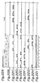
- Figure 22A shows a clock signal.
- the data of the range represented by the solid lines in Figure 21 is represented as d and d′ in Figures 22C and 22D, respectively.
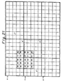
- Numbers 00 to 44 used in Figure 22 represent where each picture element of the block to be compared in Figure 21 is in the first cycle of Figure 22 when the first picture element of the block is present in R.
- 25 picture elements denoted by 00 to 44 are disposed as shown at y in Figure 22I, they cannot be compared with R by the calculation unit shown in Figure 8.
- the range represented by the solid lines in Figure 21 can be divided by the two dual lines into a lower right portion, a lower left portion, an upper right portion, and an upper left portion.
- the lower right portion consists of the picture elements 00, 01, 10, 11, 20 and 21. These picture elements are matched with the data sequence of R at the tap C′.
- the lower left portion consists of the picture elements 02, 03, 04, 12, 13, 14, 22, 23 and 24. These picture elements are matched with R at the tap C′′ according to the same consideration as the case where the block is deviated only in the horizontal direction.
- the upper right portion consists of the picture elements 30, 31, 40 and 41. These picture elements are matched with R at the tap C′′′ according to the same consideration as the case where the block is deviated only in the vertical direction.
- the upper left portion consists of the picture elements 32, 33, 34, 42, 43 and 44.
- the picture element 32 for example, is deviated from the position 00 on the screen by -2 picture elements and -3 picture elements in the horizontal and vertical directions, respectively.
- the picture element 32 is at a position which is earlier than the position 00 by 17 stages.
- the tap C′′′′ which is later than the picture element 32 by 17 stages can be used.
- a required data sequence can be obtained by switching at most the four taps C′ (-i, -j), C′′ (-i, -j), C′′′ (-i, -j) and C′′′′ (-i, -j) shown in Figure 23.
- Figure 23 shows the taps necessary in a case where blocks are deviated positively in both the horizontal and vertical directions. Since taps necessary for a case where a block is deviated positively in the horizontal direction and negatively in the vertical direction overlap with those required for other purposes, they are omitted.
- the taps in the case where the block is deviated negatively in both the horizontal and vertical directions can be used.
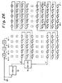
- the present embodiment can be constructed of frame memories 13 and 14 and a delay portion shown in Figure 26 and a block comparison portion shown in Figure 27.
- R can be categorised as of four types: R + +, R -+, R +- and R--.
- the output e' is not connected to taps for the first block. Thus, they are omitted. Instead, the frame memory is correspondingly delayed. In addition, with respect to the next block, 10 picture elements of the first two lines are not used. Thus, the frame memory is also delayed. Moreover, shift registers with respect to the output g are not necessary. Figure 26 does not show them. The small blocks represented by dotted lines in Figure 26 are unnecessary shift registers and they are thus omitted.
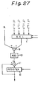
- Blocks are compared by using a circuit shown in Figure 27.
- a cumulative unit comprising a subtraction circuit 9 for subtracting data selected by a selector 1 from R, an absolute value (ABS) calculation circuit 10, an addition circuit 11, and a register 12 is used.
- R for a case where a block is deviated by i picture elements in the horizontal direction and by j picture elements in the vertical direction: when i is positive and j is positive, R ++ is used; when i is negative and j is positive, R - + is used; when i is positive and j is negative, R +- is used; and when i is negative and j is negative, R -- is used.
- a block comparison calculation circuit as shown in Figure 27 is required for each deviation amount (i, j). However, as was described earlier, part of them may be omitted.
- n sets of the amounts (i, j) can be time multiplexed to be processed in one calculation circuit. With this construction, therefore, the number of calculation units can be decreased by a factor of 1/n.
- a picture which is not interlaced was considered.
- the present invention can be applied to a case where a picture is interlaced.
- j in the abovementioned deviation (i, j) has an offset of 0.5 picture elements.
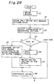
- Figure 28 shows a procedure according to the present embodiment. As opposed to the prior proposal shown in Figure 16, the distribution of the matching ratio, namely various minimum values, are not detected.
- the vector amount (x, y) with the minimum matching ratio is obtained in a step 22.
- the correlation of neighbouring (physically adjacent) vectors is obtained in a step 23.
- the block under consideration is Fourier transformed (for example).
- x and y represent the horizontal and vertical directions, respectively.
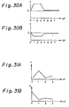
- waveforms as shown in Figures 30A and 30B are obtained.
- the horizontal axis represents a spatial position (SP), which in practice is the number i.
- the vertical axis represents an x component or a y component of a motion vector.
- Figure 30A represents the x component of the motion vector and
- Figure 30B represents the y component of the motion vector.
- Figure 31A represents a power spectrum where the waveforms have been Fourier transformed. In Figure 31A, since one fundamental wave is present, one peak occurs at a position 1 of spatial frequency (sf) on the horizontal axis.
- sf spatial frequency
- a peak takes place at the DC component.
- a frequency component with one or more particular levels is found for the data shown in Figures 31A and 31B. Thereafter, the frequency component is categorised by the spatial frequency (in a step 24 in Figure 28).
- the motion vector is a vector with the minimum matching ratio of the block under consideration.
- the vector of the block under consideration may differ from those of the neighbouring blocks.
- it is difficult to detect an isolated motion subject whether the vector with the minimum matching ratio relates to the motion subject or is the same as the neighbouring blocks should be determined in dependence upon the magnitude of the matching ratio. Thus, it seems that no special problem takes place.
- the motion compensation is performed (in a step 28).
- the motion vectors cannot be detected. In this event, the motion compensation is cancelled.
- Figures 32A to 32C are schematic diagrams illustrating adaptive block segmentation.
- an automobile which is a motion subject travels as shown in Figure 32A
- the neighbouring blocks are segmented locally into sub-blocks as shown in Figure 32B.
- the motion vector is recursively detected for each sub-block.
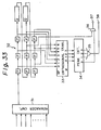
- Figure 33 shows an example of construction of a determination portion for carrying out the above-described motion vector determination procedure.
- a remainder comparison circuit 31 detects a position of deviation where the remainder per block is minimum. The result is outputted as a temporary motion vector, which is supplied to a delay circuit group 32.
- the delay circuit group 32 comprises registers P for storing a temporary motion vector and shift registers Q for storing a temporary motion vector with picture elements less than the block by 3 picture elements in the horizontal direction.
- the determination portion further comprises an orthogonal transformation circuit 33, for performing a transformation such as Fourier transformation on spatial position (SP) outputs of the delay circuit group 32, and a peak detection circuit 34 for receiving spatial frequency (sf) outputs of the circuit 33.
- SP spatial position
- sf spatial frequency
- the determination signal is supplied to a sub-block segmentation circuit.
- a motion vector is outputted.
- an alternative transformation such as a Hadamard transformation, a Hartley transformation or the like can be used.
- various wave numbers and the reference wave are correlatively calculated so as to find which wave number has the highest correlation with the reference wave.
Landscapes
- Engineering & Computer Science (AREA)
- Multimedia (AREA)
- Signal Processing (AREA)
- Computer Vision & Pattern Recognition (AREA)
- Physics & Mathematics (AREA)
- General Physics & Mathematics (AREA)
- Theoretical Computer Science (AREA)
- Compression Or Coding Systems Of Tv Signals (AREA)
- Image Processing (AREA)
- Color Television Systems (AREA)
Claims (6)
- Bewegungsvektor-Ermittlungsgerät, welches umfaßt:eine Verzögerungseinrichtung (Fig. 26, 13, 14) zum Empfangen (101) von ersten Bilddaten und zum darauf Anlegen von vorherbestimmten Verzögerungen,eine Blockvergleichseinrichtung zum Vergleichen eines Blocks von P x Q Bildelementen der verzögerten ersten Bilddaten mit mehreren Blöcken von P x Q Bildelementen von zweiten Bilddaten, die einen vorherbestimmten Zeitunterschied in bezug auf die ersten Bilddaten haben, und zum Bestimmen der Unterschiede zwischen einem Block der verzögerten ersten Bilddaten und der Blöcke der zweiten Bilddaten,
gekennzeichnet durcheine Einrichtung (31), die auf die Unterschiede anspricht, um für jeden einen der Blöcke der ersten Bilddaten einen Minimum-Bewegungsvektor in Verbindung mit einer Nachbarschaft von Blöcken zu bestimmen, die diesen einen Block und seine benachbarten Blöcke umfaßt,eine Einrichtung (32) zum Erhalten der Korrelation der Minimum-Bewegungsvektoren, wenn diese in einer vorgegebenen Reihenfolge angeordnet sind, dieser Nachbarschaft, undeine Einrichtung (33, 34) zum Bestimmen aus den korrelierten Bewegungsvektoren, ob ein Bewegungsvektor eines ausgewählten von den Blöcken der Nachbarschaft eine Bewegung an sich oder das Vorhandensein einer Bildkontur in diesem Block darstellt. - Gerät nach Anspruch 1, welches außerdem eine Einrichtung, die auf die Bestimmung des Vorhandenseins einer Bildkontur anspricht, umfaßt, um die Blöcke der Nachbarschaft zu segmentieren.
- Gerät nach Anspruch 1 oder 2, wobei die Bestimmungseinrichtung (33, 34) eine Transformiereinrichtung umfaßt, um eine Raumfrequenztransformation der korrelierten Bewegungsvektoren durchzuführen.
- Gerät nach Anspruch 3, wobei die Transformation eine Fourier-Transformation ist.
- Gerät nach Anspruch 3, wobei die Transformation eine Hadamand-Transformation oder eine Hartley-Transformation ist.
- Gerät nach einem der vorhergehenden Ansprüche, wobei der Zeitunterschied ein Teilbild oder ein Vollbild ist.
Priority Applications (1)
| Application Number | Priority Date | Filing Date | Title |
|---|---|---|---|
| EP19970201781 EP0805596A1 (de) | 1990-11-30 | 1991-11-29 | Bewegungsvektorerfassung und Bandkompressionsgerät |
Applications Claiming Priority (3)
| Application Number | Priority Date | Filing Date | Title |
|---|---|---|---|
| JP2338492A JPH04207788A (ja) | 1990-11-30 | 1990-11-30 | 画像信号符号化装置及び方法 |
| JP338492/90 | 1990-11-30 | ||
| JP33849290 | 1990-11-30 |
Related Child Applications (1)
| Application Number | Title | Priority Date | Filing Date |
|---|---|---|---|
| EP19970201781 Division EP0805596A1 (de) | 1990-11-30 | 1991-11-29 | Bewegungsvektorerfassung und Bandkompressionsgerät |
Publications (3)
| Publication Number | Publication Date |
|---|---|
| EP0488795A2 EP0488795A2 (de) | 1992-06-03 |
| EP0488795A3 EP0488795A3 (de) | 1994-02-23 |
| EP0488795B1 true EP0488795B1 (de) | 2000-01-26 |
Family
ID=18318668
Family Applications (2)
| Application Number | Title | Priority Date | Filing Date |
|---|---|---|---|
| EP19970201781 Withdrawn EP0805596A1 (de) | 1990-11-30 | 1991-11-29 | Bewegungsvektorerfassung und Bandkompressionsgerät |
| EP19910311131 Expired - Lifetime EP0488795B1 (de) | 1990-11-30 | 1991-11-29 | Bewegungsvektorerfassungsgerät |
Family Applications Before (1)
| Application Number | Title | Priority Date | Filing Date |
|---|---|---|---|
| EP19970201781 Withdrawn EP0805596A1 (de) | 1990-11-30 | 1991-11-29 | Bewegungsvektorerfassung und Bandkompressionsgerät |
Country Status (5)
| Country | Link |
|---|---|
| US (1) | US5226093A (de) |
| EP (2) | EP0805596A1 (de) |
| JP (1) | JPH04207788A (de) |
| KR (1) | KR100281148B1 (de) |
| DE (1) | DE69131938T2 (de) |
Families Citing this family (33)
| Publication number | Priority date | Publication date | Assignee | Title |
|---|---|---|---|---|
| US5400076A (en) * | 1991-11-30 | 1995-03-21 | Sony Corporation | Compressed motion picture signal expander with error concealment |
| GB9204117D0 (en) * | 1992-02-26 | 1992-04-08 | British Broadcasting Corp | Video image processing |
| US5461423A (en) * | 1992-05-29 | 1995-10-24 | Sony Corporation | Apparatus for generating a motion vector with half-pixel precision for use in compressing a digital motion picture signal |
| JPH06141304A (ja) | 1992-10-28 | 1994-05-20 | Sony Corp | 演算回路 |
| US5347311A (en) * | 1993-05-28 | 1994-09-13 | Intel Corporation | Method and apparatus for unevenly encoding error images |
| JPH07115646A (ja) * | 1993-10-20 | 1995-05-02 | Sony Corp | 画像処理装置 |
| JP2797959B2 (ja) * | 1994-03-12 | 1998-09-17 | 日本ビクター株式会社 | 多次元画像圧縮伸張方法 |
| KR100349883B1 (ko) * | 1994-07-27 | 2002-12-16 | 소니 가부시끼 가이샤 | 동작벡터검출및화상신호부호화방법및장치 |
| TW245871B (en) * | 1994-08-15 | 1995-04-21 | Gen Instrument Corp | Method and apparatus for efficient addressing of dram in a video decompression processor |
| JPH08171384A (ja) * | 1994-12-16 | 1996-07-02 | Canon Inc | 走査変換方法及びその装置 |
| JP2738325B2 (ja) * | 1995-01-24 | 1998-04-08 | 日本電気株式会社 | 動き補償フレーム間予測装置 |
| AU5027796A (en) | 1995-03-07 | 1996-09-23 | Interval Research Corporation | System and method for selective recording of information |
| WO1996033575A1 (en) * | 1995-04-18 | 1996-10-24 | Advanced Micro Devices, Inc. | Video decoder using block oriented data structures |
| US5886741A (en) * | 1995-08-18 | 1999-03-23 | Texas Instruments Incorporated | Method and apparatus for improved video coding using a zero block predictor module |
| JPH10509298A (ja) | 1995-09-15 | 1998-09-08 | インターヴァル リサーチ コーポレイション | 複数のビデオ画像の圧縮方法 |
| DE19540424C2 (de) * | 1995-10-30 | 2003-07-03 | Dinu Scheppelmann | Verfahren zum Übertragen eines digitalen Bildes |
| US5953458A (en) * | 1995-12-06 | 1999-09-14 | Thomson Multimedia S.A. | Method and device for motion estimation |
| FR2742248B1 (fr) * | 1995-12-06 | 1998-01-23 | Thomson Multimedia Sa | Procede de traitement de donnees dans des reseaux matriciels dans un systeme d'estimation de mouvement |
| GB2313011B (en) * | 1996-05-07 | 2000-10-04 | British Broadcasting Corp | Encoding and decoding of composite video |
| KR100209413B1 (ko) * | 1996-05-23 | 1999-07-15 | 전주범 | 블럭-기반 비디오 신호 부호화 시스템에 이용하기 위한그리드 결정방법 |
| US6263507B1 (en) | 1996-12-05 | 2001-07-17 | Interval Research Corporation | Browser for use in navigating a body of information, with particular application to browsing information represented by audiovisual data |
| US5893062A (en) | 1996-12-05 | 1999-04-06 | Interval Research Corporation | Variable rate video playback with synchronized audio |
| US6614845B1 (en) * | 1996-12-24 | 2003-09-02 | Verizon Laboratories Inc. | Method and apparatus for differential macroblock coding for intra-frame data in video conferencing systems |
| JP2007151169A (ja) * | 1996-12-26 | 2007-06-14 | United Module Corp | 動ベクトル検出装置および記録媒体 |
| KR100239308B1 (ko) * | 1997-02-18 | 2000-01-15 | 전주범 | 적응적 윤곽선 부호화 방법 및 그 장치 |
| US6937659B1 (en) * | 1997-11-14 | 2005-08-30 | Ac Capital Management, Inc. | Apparatus and method for compressing video information |
| US6335976B1 (en) * | 1999-02-26 | 2002-01-01 | Bomarc Surveillance, Inc. | System and method for monitoring visible changes |
| US6888958B1 (en) * | 1999-03-30 | 2005-05-03 | Kabushiki Kaisha Toshiba | Method and apparatus for inspecting patterns |
| US7155735B1 (en) | 1999-10-08 | 2006-12-26 | Vulcan Patents Llc | System and method for the broadcast dissemination of time-ordered data |
| US6757682B1 (en) | 2000-01-28 | 2004-06-29 | Interval Research Corporation | Alerting users to items of current interest |
| JP3739274B2 (ja) * | 2000-10-31 | 2006-01-25 | Kddi株式会社 | 2系統映像の位置ずれ補正装置 |
| JP4145275B2 (ja) * | 2004-07-27 | 2008-09-03 | 富士通株式会社 | 動きベクトル検出・補償装置 |
| WO2010007590A2 (en) * | 2008-07-17 | 2010-01-21 | Amimon Ltd. | Methods circuits and systems for transmission and reconstruction of a video block |
Family Cites Families (15)
| Publication number | Priority date | Publication date | Assignee | Title |
|---|---|---|---|---|
| JPS58197984A (ja) * | 1982-05-14 | 1983-11-17 | Nec Corp | テレビジヨン信号の適応予測符号化装置 |
| JPS61113377A (ja) * | 1984-11-07 | 1986-05-31 | Sony Corp | テレビジヨン信号の動き検出装置 |
| EP0186196B1 (de) * | 1984-12-25 | 1991-07-17 | Nec Corporation | Verfahren und Vorrichtung zur Kodierung/Dekodierung eines Bildsignals |
| DE3721074A1 (de) * | 1986-12-24 | 1988-07-07 | Licentia Gmbh | Schaltungsanordnung zur verschiebungsvektorsuche in der digitalen bildanalyse |
| GB2214751B (en) * | 1988-02-01 | 1992-06-17 | Plessey Co Plc | Video signal coding |
| FR2628276B1 (fr) * | 1988-03-02 | 1991-06-28 | France Etat | Procede de reduction de debit d'une sequence de donnees d'assistance a la reconstitution d'une image electronique a partir d'un signal sous-echantillonne |
| FR2648254B2 (fr) * | 1988-09-23 | 1991-08-30 | Thomson Csf | Procede et dispositif d'estimation de mouvement dans une sequence d'images animees |
| DE3835368A1 (de) * | 1988-10-18 | 1990-04-19 | Bosch Gmbh Robert | Schaltungsanordnung zum auslesen von daten aus einem bildspeicher |
| JP2563567B2 (ja) * | 1989-03-20 | 1996-12-11 | 松下電器産業株式会社 | 揺れ補正装置 |
| GB8909498D0 (en) * | 1989-04-26 | 1989-06-14 | British Telecomm | Motion estimator |
| AU612543B2 (en) * | 1989-05-11 | 1991-07-11 | Panasonic Corporation | Moving image signal encoding apparatus and decoding apparatus |
| JP3035920B2 (ja) * | 1989-05-30 | 2000-04-24 | ソニー株式会社 | 動体抽出装置及び動体抽出方法 |
| JPH03117991A (ja) * | 1989-09-29 | 1991-05-20 | Victor Co Of Japan Ltd | 動きベクトル符号化装置及び復号化装置 |
| JPH03127580A (ja) * | 1989-10-13 | 1991-05-30 | Matsushita Electric Ind Co Ltd | 動き補償フレーム間符号化装置 |
| US5491909A (en) * | 1993-08-18 | 1996-02-20 | Darco | Shock absorbing medical shoe |
-
1990
- 1990-11-30 JP JP2338492A patent/JPH04207788A/ja active Pending
-
1991
- 1991-11-27 US US07/799,308 patent/US5226093A/en not_active Expired - Lifetime
- 1991-11-29 EP EP19970201781 patent/EP0805596A1/de not_active Withdrawn
- 1991-11-29 EP EP19910311131 patent/EP0488795B1/de not_active Expired - Lifetime
- 1991-11-29 KR KR1019910021771A patent/KR100281148B1/ko not_active Expired - Fee Related
- 1991-11-29 DE DE69131938T patent/DE69131938T2/de not_active Expired - Fee Related
Non-Patent Citations (1)
| Title |
|---|
| IEEE TRANSACTIONS ON COMMUNICATIONS, vol.COM-29, no.12, 12/81, page 1799 - 1808, J.R.JAIN ET AL 'DISPLACEMENT MEASUREMENT AND ITS APPLICATION IN INTERFRAME IMAGE CODING' * |
Also Published As
| Publication number | Publication date |
|---|---|
| EP0805596A1 (de) | 1997-11-05 |
| KR920011257A (ko) | 1992-06-27 |
| EP0488795A2 (de) | 1992-06-03 |
| US5226093A (en) | 1993-07-06 |
| DE69131938T2 (de) | 2000-06-15 |
| KR100281148B1 (ko) | 2001-02-01 |
| EP0488795A3 (de) | 1994-02-23 |
| JPH04207788A (ja) | 1992-07-29 |
| DE69131938D1 (de) | 2000-03-02 |
Similar Documents
| Publication | Publication Date | Title |
|---|---|---|
| EP0488795B1 (de) | Bewegungsvektorerfassungsgerät | |
| KR100203913B1 (ko) | 모션 벡터 생성기 | |
| EP1430724B1 (de) | Bewegungsschätzung und/oder kompensation | |
| EP0560577B1 (de) | Kodierung und Dekodierung zur Videokompression mit automatischer Halbbild/Bild Bewegungskompensation auf der Subpixelebene | |
| EP0765573B1 (de) | Bewegungskompensierte interpolation | |
| US5083202A (en) | Motion detector for video signals including a novel line comparison processing scheme | |
| JPH06261310A (ja) | 移動補償されたデジタル・ビデオ・システムのための半画素補間法及び装置 | |
| US5099325A (en) | Process and circuit for block matching in two-dimensional picture signals | |
| HK1014434B (en) | Motion estimator | |
| KR100407691B1 (ko) | 계층탐색을 이용한 움직임 추정장치 및 방법 | |
| JP2005512202A (ja) | 画像データ検索 | |
| US8135224B2 (en) | Generating image data | |
| US5777681A (en) | Method of extracting color difference signal motion vector and a motion compensation in high definition television | |
| EP1420595B1 (de) | Auswahl von Bewegungsvektoren in einem Bewegungsschätzer für Videodaten auf der Basis eines Referenzpunktes | |
| US20050089099A1 (en) | Fast motion estimating apparatus | |
| US6968011B2 (en) | Motion vector detecting device improved in detection speed of motion vectors and system employing the same devices | |
| JP3192698B2 (ja) | 動きベクトル評価装置 | |
| JP2964633B2 (ja) | 画像信号符号化装置及び方法 | |
| JP2931783B2 (ja) | 動きベクトル探索装置 | |
| EP0909098B1 (de) | Vorrichtung zur Bewegungsvektordetektion | |
| KR100205146B1 (ko) | 디지탈 비데오 인코더 시스템에서 움직임 예측 방법 | |
| KR0166918B1 (ko) | 엠펙 ii의 이동량 검출장치 | |
| JPH04207777A (ja) | 動きベクトル検出装置 | |
| WO2000072590A2 (en) | Block matching | |
| IE80924B1 (en) | Motion estimator |
Legal Events
| Date | Code | Title | Description |
|---|---|---|---|
| PUAI | Public reference made under article 153(3) epc to a published international application that has entered the european phase |
Free format text: ORIGINAL CODE: 0009012 |
|
| AK | Designated contracting states |
Kind code of ref document: A2 Designated state(s): DE FR GB |
|
| PUAL | Search report despatched |
Free format text: ORIGINAL CODE: 0009013 |
|
| AK | Designated contracting states |
Kind code of ref document: A3 Designated state(s): DE FR GB |
|
| 17P | Request for examination filed |
Effective date: 19940712 |
|
| 17Q | First examination report despatched |
Effective date: 19961206 |
|
| GRAG | Despatch of communication of intention to grant |
Free format text: ORIGINAL CODE: EPIDOS AGRA |
|
| GRAG | Despatch of communication of intention to grant |
Free format text: ORIGINAL CODE: EPIDOS AGRA |
|
| GRAG | Despatch of communication of intention to grant |
Free format text: ORIGINAL CODE: EPIDOS AGRA |
|
| GRAH | Despatch of communication of intention to grant a patent |
Free format text: ORIGINAL CODE: EPIDOS IGRA |
|
| GRAH | Despatch of communication of intention to grant a patent |
Free format text: ORIGINAL CODE: EPIDOS IGRA |
|
| GRAA | (expected) grant |
Free format text: ORIGINAL CODE: 0009210 |
|
| DX | Miscellaneous (deleted) | ||
| AK | Designated contracting states |
Kind code of ref document: B1 Designated state(s): DE FR GB |
|
| REF | Corresponds to: |
Ref document number: 69131938 Country of ref document: DE Date of ref document: 20000302 |
|
| ET | Fr: translation filed | ||
| PLBE | No opposition filed within time limit |
Free format text: ORIGINAL CODE: 0009261 |
|
| STAA | Information on the status of an ep patent application or granted ep patent |
Free format text: STATUS: NO OPPOSITION FILED WITHIN TIME LIMIT |
|
| 26N | No opposition filed | ||
| REG | Reference to a national code |
Ref country code: GB Ref legal event code: IF02 |
|
| PGFP | Annual fee paid to national office [announced via postgrant information from national office to epo] |
Ref country code: DE Payment date: 20081127 Year of fee payment: 18 |
|
| PGFP | Annual fee paid to national office [announced via postgrant information from national office to epo] |
Ref country code: FR Payment date: 20081112 Year of fee payment: 18 |
|
| PGFP | Annual fee paid to national office [announced via postgrant information from national office to epo] |
Ref country code: GB Payment date: 20081126 Year of fee payment: 18 |
|
| GBPC | Gb: european patent ceased through non-payment of renewal fee |
Effective date: 20091129 |
|
| REG | Reference to a national code |
Ref country code: FR Ref legal event code: ST Effective date: 20100730 |
|
| PG25 | Lapsed in a contracting state [announced via postgrant information from national office to epo] |
Ref country code: FR Free format text: LAPSE BECAUSE OF NON-PAYMENT OF DUE FEES Effective date: 20091130 |
|
| PG25 | Lapsed in a contracting state [announced via postgrant information from national office to epo] |
Ref country code: DE Free format text: LAPSE BECAUSE OF NON-PAYMENT OF DUE FEES Effective date: 20100601 |
|
| PG25 | Lapsed in a contracting state [announced via postgrant information from national office to epo] |
Ref country code: GB Free format text: LAPSE BECAUSE OF NON-PAYMENT OF DUE FEES Effective date: 20091129 |