EP0488086B1 - Dekantierzentrifuge - Google Patents
Dekantierzentrifuge Download PDFInfo
- Publication number
- EP0488086B1 EP0488086B1 EP91119984A EP91119984A EP0488086B1 EP 0488086 B1 EP0488086 B1 EP 0488086B1 EP 91119984 A EP91119984 A EP 91119984A EP 91119984 A EP91119984 A EP 91119984A EP 0488086 B1 EP0488086 B1 EP 0488086B1
- Authority
- EP
- European Patent Office
- Prior art keywords
- discharge port
- dip
- screw conveyor
- weir
- external
- Prior art date
- Legal status (The legal status is an assumption and is not a legal conclusion. Google has not performed a legal analysis and makes no representation as to the accuracy of the status listed.)
- Expired - Lifetime
Links
- 239000007787 solid Substances 0.000 claims abstract description 55
- 239000007788 liquid Substances 0.000 claims abstract description 42
- 239000002002 slurry Substances 0.000 claims abstract description 17
- 230000002093 peripheral effect Effects 0.000 claims abstract description 10
- 239000012527 feed solution Substances 0.000 claims abstract description 9
- 238000007596 consolidation process Methods 0.000 claims description 3
- 230000007423 decrease Effects 0.000 claims description 3
- XLYOFNOQVPJJNP-UHFFFAOYSA-N water Substances O XLYOFNOQVPJJNP-UHFFFAOYSA-N 0.000 abstract description 16
- 238000000926 separation method Methods 0.000 abstract description 5
- 230000003247 decreasing effect Effects 0.000 abstract description 4
- 238000005192 partition Methods 0.000 description 6
- 239000010802 sludge Substances 0.000 description 6
- 230000000694 effects Effects 0.000 description 5
- 239000010801 sewage sludge Substances 0.000 description 3
- 239000000203 mixture Substances 0.000 description 2
- 239000002245 particle Substances 0.000 description 2
- VRDIULHPQTYCLN-UHFFFAOYSA-N Prothionamide Chemical compound CCCC1=CC(C(N)=S)=CC=N1 VRDIULHPQTYCLN-UHFFFAOYSA-N 0.000 description 1
- 238000005352 clarification Methods 0.000 description 1
- 238000011084 recovery Methods 0.000 description 1
- 238000004062 sedimentation Methods 0.000 description 1
- 238000003466 welding Methods 0.000 description 1
Images


Classifications
-
- B—PERFORMING OPERATIONS; TRANSPORTING
- B04—CENTRIFUGAL APPARATUS OR MACHINES FOR CARRYING-OUT PHYSICAL OR CHEMICAL PROCESSES
- B04B—CENTRIFUGES
- B04B1/00—Centrifuges with rotary bowls provided with solid jackets for separating predominantly liquid mixtures with or without solid particles
- B04B1/20—Centrifuges with rotary bowls provided with solid jackets for separating predominantly liquid mixtures with or without solid particles discharging solid particles from the bowl by a conveying screw coaxial with the bowl axis and rotating relatively to the bowl
- B04B2001/2041—Centrifuges with rotary bowls provided with solid jackets for separating predominantly liquid mixtures with or without solid particles discharging solid particles from the bowl by a conveying screw coaxial with the bowl axis and rotating relatively to the bowl with baffles, plates, vanes or discs attached to the conveying screw
Definitions
- This invention relates to a decanter centrifuge having an excellent ability of liquid-solids separation.
- Decanter centrifuges are sedimentation centrifuges used in clarification, dewatering and classification for the mixture of solids and liquid (slurry).
- the decanter centrifuge has a screw conveyor in a rotating bowl.
- the decanter centrifuge has a structure allowing that the solids in the slurry introduced from a slurry feeding pipe inserted into the screw conveyor are sedimented on the inner surface of the rotating bowl due to centrifugal force. Then, the solids are scraped together toward one end of the rotating bowl to be discharged by the screw conveyor rotating with a predetermined rotative speed being different from that of the rotating bowl. Simultaneously, the separated liquid is discharged automatically from the other end of the rotating bowl by liquid pressure due to the centrifugal force.
- dip weirs (baffles) are generally not provided. Because, if the dip weirs are provided, efficient dewatering can not be attained. However, some decanter centrifuges provided with dip weirs are proposed in order to obtain the specific reasons respectively.
- the baffle or the dip weir is provided in order to improve liquid-solids separating efficiency in the conical portion, while the straight shell has a mechanism for transporting the solids using conveyor means. That is to say, in the conventional centrifuge, the straight shell does not have mechanism of improving the concentrating efficiency for a feed solution and the dewatering efficiency for a cake. Therefore, in the prior art, the water content in the cake depends on the degree of a centrifugal force produced in the straight shell, the length of the residents time of the feed solution in the straight shell and dewatering efficiency for the feed solution in the conical portion.
- a decanter centrifuge comprises: a rotating bowl, which is provided with a solid discharge port and a clarified liquid discharge port; a screw conveyor, which comprises a straight shell and a conical portion and which is formed coaxially with the rotating bowl so as to be included in the rotating bowl, while the rotating bowl and the screw conveyor are rotated in the same direction with a differential rotative speed and while a feed solution to be separated is introduced into a ring-shaped space formed between the rotating bowl and the screw conveyor and is continuously separated to be solids and liquid by means of a centrifugal force so that the solids are discharged from the solid discharge port and the liquid is discharged from the clarified liquid discharge port; a slurry feeding port, which is formed on the wall of the straight shell of the screw conveyor and from which the feed solution to be separated is fed to the ring-shaped space; at least one dip weir, which is fixed to the external periphery of the wall of the straight shell of the screw conveyor on the solid discharge port-side away from the
- plural number of dip weirs are fixed to the external periphery of the wall of the straight shell of the screw conveyor and the dip weirs have the overflow holes respectively so that the overflow hole decreases in the length on the radius direction as the dip weir locates closer to the solid discharge port.
- the distance between the external periphery of the dip weir and the internal periphery of the rotating bowl becomes shorter as the dip weir locates closer to the solid discharge port.
- the conical portion of the screw conveyor is provided so as to connect to the solid discharge port-side end of the straight shell of the screw conveyor and if the external edge of the dip weir locates closer to the rotating axis of the screw conveyor compared with the periphery of the straight shell-side end of the conical protion, this end substantially acts as the dip weir.
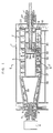
- the decanter centrifuge related to the present invention has the structure stated below.
- a rotating bowl 2 and a screw conveyor 3 are included in a casing 1.
- the rotating bowl 2 is rotated with a predetermined rotative speed by a rotational force, which is obtained from a driving motor (not shown) through a bearing 22 by means of a pulley and a pulley belt drum 21.
- a rotational force which is obtained from a driving motor (not shown) through a bearing 22 by means of a pulley and a pulley belt drum 21.
- another rotational force is transformed through a gear unit 4 to a shaft end portion 6 supported by a bearing 5.
- the screw conveyor 3 and the rotating bowl 2 can be rotated in the same direction with a predetermined differential rotative speed.
- the above rotating bowl 2 is provided with a side wall 20 at the one end of its longitudinal direction while its another end is totally open.
- the mixture of liquid and solids such as sludge can be fed through a feed pipe 7, which is inserted through the center portion of the side wall 20 with allowance.
- a ring-shaped clarified liquid discharge port 8 is formed at the internal periphery of the side wall 20.
- a ring-shaped weir board 10 is formed so as to cover the clarified liquid discharge port 8 partly in order to control the level of the clarified liquid. Thus, only the clarified liquid can be discharged from the discharge port 8.
- a space formed between the rotating bowl 2 and the screw conveyor 3 is used as a solid discharge port 9.
- the screw conveyor 3 comprises a straight shell 3A and a conical portion 3B.
- a partition wall 34 is provided in the straight shell 3A so as to cross it at its substantial center. Due to this partition wall 34, the flow of the introduced slurry can be changed.
- a slurry feeding port 35 is formed on the wall of the straight shell 3A so that the slurry can be fed through a ring-shaped space formed between the rotating bowl 2 and the screw conveyor 3.
- Screw blades 30 are fixed to the external periphery of the wall of the straight shell 3A so as to encircle the straight shell 3A. Due to these screw blades 30, the solids are transported toward the solid discharge port 9.
- the first dip weir 32 and the second dip weir 33 are fixed to the external periphery of the wall of the straight shell 3A so as to encircle the straight shell 3A on the solid discharge port-side away from the slurry feeding port 35.
- Overflow holes 32a, 33a are formed at the internal periphery-sides of the dip weirs 32, 33 respectively so that the liquid goes through the overflow holes 32a, 33a.
- the external peripheral edge of the overflow hole 32a, 33a locates closer to the axis of the screw conveyor 3 compared with the internal edge of the weir board 10 provided on the clarified liquid discharge port 8.
- the external peripheral edge of the overflow hole 32a, 33a locates closer to the axis of the screw conveyor 3 compared with the external edge of the clarified liquid discharge port 8. Further, as shown in Fig. 4, the distance l2 between the external edge of the second dip weir 33 and the rotating bowl 2 is shorter than the distance l1 between the external edge of the first dip weir 32 and the rotating bowl 2. Then, as shown in Fig. 3, the overflow hole 33a of the second dip weir 33 locates internal side as compared with the overflow hole 32a of the first dip weir 32. As shown in Fig. 1, the conical portion 3B has the shape of truncated cone tapered toward the solid discharge port 9.
- the screw blades 31 are fixed to the external periphery of the wall of the conical portion 3B so that the above mentioned sedimented solids are transformed in the form of cake.
- the distance l3 between the straight shell-side peripheral end of the conical portion 3B and the rotating bowl 2 is smaller than the distance l2
- the concentration of the solid layer is higher on the internal surface -side of the rotating bowl 2 than on the rotating axis-side. Then, a force is applied to the solid layer so that the solid layer can be transported toward the solid discharge port 9 with the screw conveyor 3. In this situation, the solid layer goes through the space formed between the first dip weir 32 and the rotating bowl 2 against the resistance, thereby a consolidation force is applied to the solid layer. Therefore, only a heavy layer, which has large solid content and small water content, can go through the first dip weir 32.
- this heavy layer residents between the first dip weir 32 and the screw blade 30 disposed at the solid discharge port-side of the first dip weir 32.
- a centrifugal force is applied to the heavy layer so that the separation of the light layer from the heavy layer is further advanced.
- the separated light layer is overflown the overflow hole 32a so as to be returned toward the slurry feeding port 35.
- the solid layer can be consolidated, while the slurry having large water content can be returned so that only the heavy layer can be transported toward the solid discharge port 9.
- the water content in the solid layer decreases in the stages of the dip weirs 32, 33, as the solid layer is transported closer to the solid discharge port 9.
- the external peripheral edge of the overflow hole 32a, 33a locates closer to the rotating axis of the screw conveyor 3 compared with the internal edge of the weir board 10 provided on the clarified liquid discharge port 8. Accordingly, the slurry having large water content is overflown so as to be returned toward the clarified liquid discharge port 8.
- the separated liquid is partly overflown the overflow holes 32a, 33a of the dip weirs 32, 33 and the weir board 10 provided on the clarified liquid discharge port 8. Then, the liquid is discharged from this port 8.
- one dip weir is enough. However, three or more than three dip weirs can be applied.
- the shape of the overflow hole can be selected optionally.
- Each dip weir is fixed to the straight shell 3A by welding so as not to be removed.
- the dip weir is ring-shaped and its internal periphery has larger diameter than that of the straight shell 3A, it can be fixed to the straight shell 3A with a stay member. In this case, the overflow hole is also ring-shaped.
- Each applied decanter centrifuge has a bowl diameter of 460 mm ⁇ and the bowl length of 1200 mmL.
- the examples are performed with three kinds of decanter centrifuges; two kinds of conventional apparatuses and one kind of apparatus of the present invention.
- one apparatus of the present invention is compared with the conventional apparatuses.
- the first conventional apparatus has a dry zone in the conical portion and a dip weir or another equipment like this is not provided in the screw.
- the second conventional apparatus has a partition wall 37 at the inlet of the conical portion 3B and a dry zone is not provided.
- the apparatus of the present invention as shown in Fig. 4, two dip weirs are provided in the straight shell 3A.
- the partition mechanism is provided at the inlet of the conical portion 3B, like the second conventional apparatus.
- the distance l1 between the first dip weir 32 and the rotating bowl 2 is 50 mm.
- the distance l2 formed between the second dip weir 33 and the rotating bowl 2 is 35 mm.
- the distance l3 between the partition wall 37 and the rotating bowl 2 is 30 mm.
- the overflow level of the external peripheral edge of the overflow hole 33a of the second dip weir 33 is the same as the standard, the overflow level of the external peripheral edge of the overflow hole 32a of the first dip weir 32 is 1.5 mm below the standard (-1.5mm) and the level of the external edge of the clarified liquid discharge port is 3 mm below the standard (-3mm).
- the centrifuge of the present invention shows following effects. Comparing with the first conventional apparatus, on the condition that the throughput is the same, the water content in the cake can be decreased by ca. 4 % with the apparatus of the present invention. On the condition of the same water content, much sludge cart be processed by more than ca. 30%. Then, comparing with the second conventional apparatus, on the condition that the throughput is the same, the water content in the cake can be decreased by ca. 2 % with the apparatus of the present invention. On the condition of the same water content, much sludge can be processed by more than ca. 30%.
- A indicates the position A shown in Fig. 4.
- B indicates the position B shown in Fig. 4.
- X indicates that the dip weir does not have the overflow hole.
- O indicates that the dip weir has at least one overflow cavity.
- h1 indicates the level of the external edge of the clarified liquid discharge port.
- h2 indicates the level of the external edge of the overflow hole of the first dip weir.
- the centrifuge which has the overflow hole can be used with more efficient dewatering. Precisely, the water content in the cake can be decreased by ca. 2.0 %. This effect can be attained regardless to the number of dip weir.
- the overflow hole is provided, when there is no difference between the levels of the weirs (as apparatus No.5 in Table 2), the water content in the cake is increased as compared with the case where there is level difference. Therefore, it is understood that the liquid layer having large water content is overflown so as to be returned toward the clarified liquid discharge port due to the level difference.
- the centrifuge provided with two dip weirs can be used with more efficient dewatering.
Landscapes
- Centrifugal Separators (AREA)
Claims (4)
- Dekantierzentrifuge mit:- einem Rotations-Behälter (2) mit einem Feststoffauslaß (9) und einem Auslaß (8) für geklärte Flüssigkeit;- einem koaxial zum Rotations-Behälter (2) angeordneten Schraubenförderer (3) mit einem geradwandigen Hülsenabschnitt (3a) und einem konischen Abschnitt (3b), der in diesem Rotations-Behälter (2) eingeschlossen ist,wobei- der Rotations-Behälter (2) und der Schraubenförderer (3) in der gleichen Richtung mit unterschiedlichen Rotationsgeschwindigkeiten gedreht werden,- eine zugeführte, aufzutrennende Lösung in den ringförmigen Raum zwischen dem Rotations-Behälter (2) und dem Schraubenförderer (3) eingebracht und kontinuierlich in Feststoff und Flüssigkeit durch die Zentrifugalkraft getrennt wird, so daß die Feststoffe aus dem Feststoffauslaß (9) und die Flüssigkeit aus dem Auslaß (8) für geklärte Flüssigkeit ausgebracht werden;- durch eine Aufschlämmungszufuhröffnung (35) in der Wand des geradwandigen Hülsenabschnitts (3a) die zugeführte, aufzutrennende Losung in den ringförmigen Raum eingebracht wird;- mindestens ein außen am Umfang der Wand des geradwandigen Hülsenabschnitts (3a) des Schraubenförderers (3) angeordnetes Wehr (32,33) auf der Seite des Feststoffauslasses, entgegengesetzt dem Aufschlämmungssufuhreinlaß (35) ausgebildet ist, während zwischen dem äußeren Umfang des Wehrs (32,33) und dem inneren Umfang des Rotations-Behälters (2) ein Abstand (l₁,l₂) besteht, wobei der radiale Abstand zwischen dem Außen-Umfang des Wehrs (32,33) und der Innenseite des Rotations-Behälters (2) so groß ist, daß der resultierende ringförmige Raum die durch den Schraubenförderer erzwungene Bewegung einer Feststoffschicht durch ihn unter Verfestigung der Feststoffschicht begrenzt;
gekennzeichnet durch- mindestens eine Überlauföffnung (32a,33a) auf der Innen-Seite des Wehrs (32,33), so daß die Flüssigkeit durch die Überlauföffnung (32a,33a) tritt, während die Außen-Umfangskante der Überlauföffnung (32a,33a) näher an der Drehachse des Schraubenförderers (3), verglichen mit der Außenkante des Auslasses für geklärte Flüssigkeit (8) oder der auf dem Auslaß für geklärte Flüssigkeit vorgesehenen Innenkante eines Wehr-Blechs (10) liegt. - Dekantierzentrifuge nach Anspruch 1, wobei mehrere Wehre (32,33) am Außenumfang der Wand des geradwandigen Hülsenabschnitts (3a) des Schraubenförderers (3) ausgebildet sind, wobei Überlauföffnungen (32a,33a) jeweils so in den Wehren (32,33) ausgebildet sind, daß die Überlauföffnung (32a,33a) in Richtung des Radius kleiner wird, je näher das Wehr (32,33) am Feststoffauslaß (9) ist.
- Dekantierzentrifuge nach Anspruch 1, wobei mehrere Wehre (32,33) am Außenumfang der Wand des geradwandigen Hülsenabschnitts (3a) des Schraubenförderers (3) befestigt sind, wobei der Abstand (l₁,l₂) zwischen dem äußeren Umfang des Wehrs (32,33) und dem inneren Umfang des Rotations-Behälters (2) abnimmt, wenn das Wehr (32,33) näher am Feststoffauslaß (9) liegt.
- Dekantierzentrifuge nach Anspruch 1, wobei der konische Abschnitt (3b) am feststoffauslaßseitigen Ende des geradwandigen Hülsenabschnitts (3a) des Schraubenförderers (3) ausgebildet ist, wobei die Außenkante der Wehre (32,33) näher an der Rotations-Achse des Schraubenförderers (3) verläuft als die Peripherie des Endes des konischen Abschnitts (3b) am geradwandigen Hülsenabschnitt (3b).
Applications Claiming Priority (2)
| Application Number | Priority Date | Filing Date | Title |
|---|---|---|---|
| JP323864/90 | 1990-11-27 | ||
| JP2323864A JP3032283B2 (ja) | 1990-11-27 | 1990-11-27 | デカンタ型遠心分離機 |
Publications (3)
| Publication Number | Publication Date |
|---|---|
| EP0488086A2 EP0488086A2 (de) | 1992-06-03 |
| EP0488086A3 EP0488086A3 (en) | 1992-08-26 |
| EP0488086B1 true EP0488086B1 (de) | 1995-04-12 |
Family
ID=18159444
Family Applications (1)
| Application Number | Title | Priority Date | Filing Date |
|---|---|---|---|
| EP91119984A Expired - Lifetime EP0488086B1 (de) | 1990-11-27 | 1991-11-22 | Dekantierzentrifuge |
Country Status (5)
| Country | Link |
|---|---|
| US (1) | US5306225A (de) |
| EP (1) | EP0488086B1 (de) |
| JP (1) | JP3032283B2 (de) |
| AT (1) | ATE120987T1 (de) |
| DE (1) | DE69108868T2 (de) |
Families Citing this family (19)
| Publication number | Priority date | Publication date | Assignee | Title |
|---|---|---|---|---|
| DE4231063A1 (de) * | 1992-09-17 | 1994-03-24 | Westfalia Separator Ag | Vollmantel-Schneckenzentrifuge zum Klären oder Trennen eines Flüssigkeits-Feststoffgemisches |
| US5562617A (en) * | 1994-01-18 | 1996-10-08 | Finch, Jr.; Charles D. | Implantable vascular device |
| US5653673A (en) * | 1994-06-27 | 1997-08-05 | Amoco Corporation | Wash conduit configuration in a centrifuge apparatus and uses thereof |
| US6030332A (en) * | 1998-04-14 | 2000-02-29 | Hensley; Gary L. | Centrifuge system with stacked discs attached to the housing |
| US6860845B1 (en) | 1999-07-14 | 2005-03-01 | Neal J. Miller | System and process for separating multi phase mixtures using three phase centrifuge and fuzzy logic |
| DE19952804C2 (de) * | 1999-11-02 | 2003-07-03 | Westfalia Separator Ind Gmbh | Vollmantel-Schneckenzentrifuge zur Verarbeitung eines zur Schäumung neigenden Schleudergutes |
| US6572524B1 (en) * | 2000-07-14 | 2003-06-03 | Alfa Laval Inc. | Decanter centrifuge having a heavy phase solids baffle |
| DE10212187A1 (de) * | 2002-03-20 | 2003-10-02 | Hiller Gmbh | Schneckenzentrifuge |
| DK200200598A (da) * | 2002-04-22 | 2003-10-23 | Alfa Laval Copenhagen As | Dekantercentrifuge |
| DE10220757B4 (de) * | 2002-05-08 | 2004-06-24 | Westfalia Separator Ag | Zentrifuge, insbesondere Separator |
| DE10223802B4 (de) * | 2002-05-29 | 2005-06-09 | Westfalia Separator Ag | Vollmantel-Schneckenzentrifuge |
| SE525413C2 (sv) * | 2003-06-18 | 2005-02-15 | Alfa Laval Corp Ab | En skruvtransportör för en dekantercentrifug |
| US7908764B1 (en) | 2008-05-05 | 2011-03-22 | Decanter Machines, Inc. | Hyperbaric centrifuge system |
| JP2013154327A (ja) * | 2012-01-31 | 2013-08-15 | Ihi Corp | 遠心脱水機 |
| CN103272705A (zh) * | 2013-06-04 | 2013-09-04 | 无锡市博迪电子设备有限公司 | 用于离心分离器转子单元的盘组件 |
| CN104190556A (zh) * | 2014-08-05 | 2014-12-10 | 安徽奥冠环保设备制造有限公司 | 一种高干型卧式螺旋离心机差速器 |
| CN105880038B (zh) * | 2016-04-07 | 2018-05-15 | 安徽普源分离机械制造有限公司 | 一种自来水污泥彻底分离设备 |
| CN115646665A (zh) * | 2022-09-26 | 2023-01-31 | 重庆江北机械有限责任公司 | 一种卧螺离心机螺旋结构 |
| KR102707664B1 (ko) * | 2024-04-05 | 2024-09-19 | 주식회사 센텍기술 | 유분 분리 효율이 향상된 복합 원심분리기 |
Family Cites Families (26)
| Publication number | Priority date | Publication date | Assignee | Title |
|---|---|---|---|---|
| DE682714C (de) * | 1937-09-28 | 1939-10-21 | Hans Joachim V Klinkowstroem | Verfahren und Vorrichtung zur Erzielung einer eingeschraenkten Beleuchtung fuer Luftschutzzwecke |
| US2831575A (en) * | 1954-12-16 | 1958-04-22 | Raibl Societa Miniraria Del Pr | Centrifugal classifier for finely granulated solid substances in suspension |
| CH418982A (de) * | 1964-06-24 | 1966-08-15 | Escher Wyss Ag | Klärzentrifuge zum Scheiden einer Suspension in Flüssigkeit und Feststoff |
| IS679B6 (is) * | 1965-10-21 | 1969-04-22 | Alfa-Laval Ab | Tilhögun við að aðskilja aurleðju í skilvindu. |
| DE2130633C3 (de) * | 1971-06-21 | 1982-09-23 | Flottweg-Werk Dr. Georg Bruckmayer GmbH & Co. KG, 8313 Vilsbiburg | Vollmantel-Schneckenzentrifuge |
| DE2154558A1 (de) * | 1971-11-03 | 1973-05-10 | Georg Hiller | Vollmantelschneckenzentrifuge |
| AR205952A1 (es) * | 1975-01-03 | 1976-06-15 | Pennwalt Corp | Una centrifuga decantadora |
| DE2701763C3 (de) * | 1977-01-18 | 1979-11-15 | Westfalia Separator Ag, 4740 Oelde | Kontinuierlich arbeitender Vollmantel-Gegenstrom-Zentrifugalextraktor |
| JPS54139167A (en) * | 1978-03-23 | 1979-10-29 | Kobe Steel Ltd | Axial-flow decanter-shaped centrifugal separator |
| JPS5610353A (en) * | 1979-07-05 | 1981-02-02 | Suguru Katsume | Completely-enclosed type screw-carrying centrifugal separator |
| AU538688B2 (en) * | 1979-10-20 | 1984-08-23 | Klockner-Humboldt-Deutz Aktiengesellschaft | Discharge control device for centrifuge |
| DE3027020A1 (de) * | 1980-07-17 | 1982-02-04 | Klöckner-Humboldt-Deutz AG, 5000 Köln | Vollmantelzentrifuge zum stoffaustausch zwischen fluessigkeiten |
| JPS5735849A (en) * | 1980-08-12 | 1982-02-26 | Ricoh Co Ltd | Image forming material |
| DE3202294C1 (de) * | 1982-01-26 | 1983-04-21 | Westfalia Separator Ag, 4740 Oelde | Kontinuierlich arbeitender Vollmantel-Gegenstrom-Zentrifugalextraktor |
| JPS59169550A (ja) * | 1983-03-16 | 1984-09-25 | Mitsubishi Heavy Ind Ltd | 遠心分離機 |
| US4743226A (en) * | 1983-04-29 | 1988-05-10 | Geosource Inc. | High capacity continuous solid bowl centrifuge |
| DE3318064A1 (de) * | 1983-05-18 | 1984-11-22 | Klöckner-Humboldt-Deutz AG, 5000 Köln | Verfahren und vorrichtung zur trennung eines feststoff-fluessigkeitsgemisches |
| DE3318793A1 (de) * | 1983-05-24 | 1985-01-24 | KHD Humboldt Wedag AG, 5000 Köln | Vorrichtung zum entfeuchten von schlamm |
| GB8328894D0 (en) * | 1983-10-28 | 1983-11-30 | Broadbent & Sons Ltd Thomas | Decanting type centrifuges |
| DE3436168A1 (de) * | 1984-10-03 | 1986-04-10 | Klöckner-Humboldt-Deutz AG, 5000 Köln | Verfahren und vorrichtung zur entwaesserung von schlamm |
| SU1329826A1 (ru) * | 1985-08-14 | 1987-08-15 | Комплексный научно-исследовательский и проектно-конструкторский институт обогащения твердых горючих ископаемых | Осадительна центрифуга |
| JPS6243745A (ja) * | 1985-08-21 | 1987-02-25 | Alps Electric Co Ltd | 情報処理装置 |
| US4731182A (en) * | 1985-11-18 | 1988-03-15 | Decanter Pty. Limited | Decanter centrifuge |
| JPS6419941A (en) * | 1987-07-10 | 1989-01-24 | Fuji Electric Co Ltd | Dc rotating electric machine |
| JPH01218650A (ja) * | 1988-02-29 | 1989-08-31 | Nishihara Environ Sanit Res Corp | 連続排出型遠心分離機 |
| JP6243745B2 (ja) | 2014-01-27 | 2017-12-06 | 株式会社スギノマシン | 流体ノズル |
-
1990
- 1990-11-27 JP JP2323864A patent/JP3032283B2/ja not_active Expired - Lifetime
-
1991
- 1991-11-22 AT AT91119984T patent/ATE120987T1/de not_active IP Right Cessation
- 1991-11-22 DE DE69108868T patent/DE69108868T2/de not_active Expired - Lifetime
- 1991-11-22 EP EP91119984A patent/EP0488086B1/de not_active Expired - Lifetime
-
1993
- 1993-05-17 US US08/062,030 patent/US5306225A/en not_active Expired - Lifetime
Also Published As
| Publication number | Publication date |
|---|---|
| JP3032283B2 (ja) | 2000-04-10 |
| EP0488086A3 (en) | 1992-08-26 |
| DE69108868D1 (de) | 1995-05-18 |
| ATE120987T1 (de) | 1995-04-15 |
| DE69108868T2 (de) | 1995-09-14 |
| EP0488086A2 (de) | 1992-06-03 |
| JPH04193363A (ja) | 1992-07-13 |
| US5306225A (en) | 1994-04-26 |
Similar Documents
| Publication | Publication Date | Title |
|---|---|---|
| EP0488086B1 (de) | Dekantierzentrifuge | |
| US4037781A (en) | Decanter centrifuge apparatus | |
| US3795361A (en) | Centrifuge apparatus | |
| US4362620A (en) | Partitioned centrifuge | |
| GB1596122A (en) | Gravitational separation | |
| JPS59206062A (ja) | 固体ボウル遠心分離機 | |
| EP0971856B1 (de) | Dreizonenvorrichtung zur reinigung durch flotation mit gelöster luft mit verbessertem wirkungsgrad | |
| DE69122665D1 (de) | Trennungssysteme | |
| US4714456A (en) | Solid bowl centrifuge with terminal clarification device | |
| JPH0649157B2 (ja) | 高さの異る堰を備えた遠心分離機 | |
| EP0016690B1 (de) | Vorrichtung zur Abscheidung fester Suspensionsteilchen in einem Flüssigkeitsstrom | |
| JPS62152556A (ja) | ダブルカントデカンタによる3相分離装置 | |
| CA1325982C (en) | Filter bed clarifier | |
| EP0447742B1 (de) | Dekantierzentrifuge | |
| DE3634323C2 (de) | Verfahren und Vorrichtung zur Fliehkrafttrennung eines Flotationssuspensionsgemisches | |
| US6719911B2 (en) | Apparatus and method for the treatment of a contaminated fluid | |
| US3260369A (en) | Means for centrifugally clarifying water containing sewage sludges and the like | |
| US4915681A (en) | Centrifugal separator with continuous discharge | |
| WO1993020946A1 (en) | Apparatus for separating materials | |
| US3423016A (en) | Continuously operating solid-bowl centrifuge | |
| SU927102A3 (ru) | Центрифуга дл обезвоживани отсто сточных вод | |
| JPH10151369A (ja) | 多層混合物の遠心分離方法及びスクリューデカンター型遠心分離装置 | |
| RU2185892C2 (ru) | Центрифуга для разделения суспензий | |
| JP3945856B2 (ja) | 液・固−液分離用スクリュウ型デカンター | |
| JP3748798B2 (ja) | 遠心分離機 |
Legal Events
| Date | Code | Title | Description |
|---|---|---|---|
| PUAI | Public reference made under article 153(3) epc to a published international application that has entered the european phase |
Free format text: ORIGINAL CODE: 0009012 |
|
| AK | Designated contracting states |
Kind code of ref document: A2 Designated state(s): AT BE CH DE DK ES FR GB GR IT LI LU NL SE |
|
| PUAL | Search report despatched |
Free format text: ORIGINAL CODE: 0009013 |
|
| AK | Designated contracting states |
Kind code of ref document: A3 Designated state(s): AT BE CH DE DK ES FR GB GR IT LI LU NL SE |
|
| 17P | Request for examination filed |
Effective date: 19921204 |
|
| 17Q | First examination report despatched |
Effective date: 19931116 |
|
| GRAA | (expected) grant |
Free format text: ORIGINAL CODE: 0009210 |
|
| AK | Designated contracting states |
Kind code of ref document: B1 Designated state(s): AT BE CH DE DK ES FR GB GR IT LI LU NL SE |
|
| PG25 | Lapsed in a contracting state [announced via postgrant information from national office to epo] |
Ref country code: DK Effective date: 19950412 Ref country code: GR Free format text: LAPSE BECAUSE OF FAILURE TO SUBMIT A TRANSLATION OF THE DESCRIPTION OR TO PAY THE FEE WITHIN THE PRESCRIBED TIME-LIMIT Effective date: 19950412 Ref country code: ES Free format text: THE PATENT HAS BEEN ANNULLED BY A DECISION OF A NATIONAL AUTHORITY Effective date: 19950412 Ref country code: NL Free format text: LAPSE BECAUSE OF NON-PAYMENT OF DUE FEES Effective date: 19950412 |
|
| REF | Corresponds to: |
Ref document number: 120987 Country of ref document: AT Date of ref document: 19950415 Kind code of ref document: T |
|
| REF | Corresponds to: |
Ref document number: 69108868 Country of ref document: DE Date of ref document: 19950518 |
|
| ITF | It: translation for a ep patent filed | ||
| ET | Fr: translation filed | ||
| PG25 | Lapsed in a contracting state [announced via postgrant information from national office to epo] |
Ref country code: SE Effective date: 19950712 |
|
| NLV1 | Nl: lapsed or annulled due to failure to fulfill the requirements of art. 29p and 29m of the patents act | ||
| PLBE | No opposition filed within time limit |
Free format text: ORIGINAL CODE: 0009261 |
|
| STAA | Information on the status of an ep patent application or granted ep patent |
Free format text: STATUS: NO OPPOSITION FILED WITHIN TIME LIMIT |
|
| 26N | No opposition filed | ||
| PGFP | Annual fee paid to national office [announced via postgrant information from national office to epo] |
Ref country code: BE Payment date: 19981119 Year of fee payment: 8 Ref country code: LU Payment date: 19981119 Year of fee payment: 8 |
|
| PGFP | Annual fee paid to national office [announced via postgrant information from national office to epo] |
Ref country code: CH Payment date: 19981126 Year of fee payment: 8 |
|
| PG25 | Lapsed in a contracting state [announced via postgrant information from national office to epo] |
Ref country code: LU Free format text: LAPSE BECAUSE OF NON-PAYMENT OF DUE FEES Effective date: 19991122 |
|
| PG25 | Lapsed in a contracting state [announced via postgrant information from national office to epo] |
Ref country code: LI Free format text: LAPSE BECAUSE OF NON-PAYMENT OF DUE FEES Effective date: 19991130 Ref country code: BE Free format text: LAPSE BECAUSE OF NON-PAYMENT OF DUE FEES Effective date: 19991130 Ref country code: CH Free format text: LAPSE BECAUSE OF NON-PAYMENT OF DUE FEES Effective date: 19991130 |
|
| BERE | Be: lapsed |
Owner name: TSUKISHIMA KIKAI CO. LTD Effective date: 19991130 |
|
| REG | Reference to a national code |
Ref country code: CH Ref legal event code: PL |
|
| PGFP | Annual fee paid to national office [announced via postgrant information from national office to epo] |
Ref country code: AT Payment date: 20001122 Year of fee payment: 10 |
|
| PG25 | Lapsed in a contracting state [announced via postgrant information from national office to epo] |
Ref country code: AT Free format text: LAPSE BECAUSE OF NON-PAYMENT OF DUE FEES Effective date: 20011122 |
|
| REG | Reference to a national code |
Ref country code: GB Ref legal event code: IF02 |
|
| PGFP | Annual fee paid to national office [announced via postgrant information from national office to epo] |
Ref country code: GB Payment date: 20021029 Year of fee payment: 12 |
|
| PGFP | Annual fee paid to national office [announced via postgrant information from national office to epo] |
Ref country code: FR Payment date: 20021118 Year of fee payment: 12 |
|
| PG25 | Lapsed in a contracting state [announced via postgrant information from national office to epo] |
Ref country code: GB Free format text: LAPSE BECAUSE OF NON-PAYMENT OF DUE FEES Effective date: 20031122 |
|
| GBPC | Gb: european patent ceased through non-payment of renewal fee |
Effective date: 20031122 |
|
| PG25 | Lapsed in a contracting state [announced via postgrant information from national office to epo] |
Ref country code: FR Free format text: LAPSE BECAUSE OF NON-PAYMENT OF DUE FEES Effective date: 20040730 |
|
| REG | Reference to a national code |
Ref country code: FR Ref legal event code: ST |
|
| PG25 | Lapsed in a contracting state [announced via postgrant information from national office to epo] |
Ref country code: IT Free format text: LAPSE BECAUSE OF NON-PAYMENT OF DUE FEES Effective date: 20051122 |
|
| PGFP | Annual fee paid to national office [announced via postgrant information from national office to epo] |
Ref country code: DE Payment date: 20110128 Year of fee payment: 20 |
|
| REG | Reference to a national code |
Ref country code: DE Ref legal event code: R071 Ref document number: 69108868 Country of ref document: DE |
|
| REG | Reference to a national code |
Ref country code: DE Ref legal event code: R071 Ref document number: 69108868 Country of ref document: DE |
|
| PG25 | Lapsed in a contracting state [announced via postgrant information from national office to epo] |
Ref country code: DE Free format text: LAPSE BECAUSE OF EXPIRATION OF PROTECTION Effective date: 20111123 |