EP0486876B1 - Maschinenelement mit mindestens einem mit Druck auf einer Welle befestigten Verbindungsteil - Google Patents
Maschinenelement mit mindestens einem mit Druck auf einer Welle befestigten Verbindungsteil Download PDFInfo
- Publication number
- EP0486876B1 EP0486876B1 EP91118912A EP91118912A EP0486876B1 EP 0486876 B1 EP0486876 B1 EP 0486876B1 EP 91118912 A EP91118912 A EP 91118912A EP 91118912 A EP91118912 A EP 91118912A EP 0486876 B1 EP0486876 B1 EP 0486876B1
- Authority
- EP
- European Patent Office
- Prior art keywords
- shaft
- protrusions
- bore
- fitting member
- machine element
- Prior art date
- Legal status (The legal status is an assumption and is not a legal conclusion. Google has not performed a legal analysis and makes no representation as to the accuracy of the status listed.)
- Expired - Lifetime
Links
Images

Classifications
-
- B—PERFORMING OPERATIONS; TRANSPORTING
- B21—MECHANICAL METAL-WORKING WITHOUT ESSENTIALLY REMOVING MATERIAL; PUNCHING METAL
- B21D—WORKING OR PROCESSING OF SHEET METAL OR METAL TUBES, RODS OR PROFILES WITHOUT ESSENTIALLY REMOVING MATERIAL; PUNCHING METAL
- B21D53/00—Making other particular articles
- B21D53/84—Making other particular articles other parts for engines, e.g. connecting-rods
- B21D53/845—Making camshafts
-
- B—PERFORMING OPERATIONS; TRANSPORTING
- B23—MACHINE TOOLS; METAL-WORKING NOT OTHERWISE PROVIDED FOR
- B23P—METAL-WORKING NOT OTHERWISE PROVIDED FOR; COMBINED OPERATIONS; UNIVERSAL MACHINE TOOLS
- B23P11/00—Connecting or disconnecting metal parts or objects by metal-working techniques not otherwise provided for
-
- F—MECHANICAL ENGINEERING; LIGHTING; HEATING; WEAPONS; BLASTING
- F01—MACHINES OR ENGINES IN GENERAL; ENGINE PLANTS IN GENERAL; STEAM ENGINES
- F01L—CYCLICALLY OPERATING VALVES FOR MACHINES OR ENGINES
- F01L1/00—Valve-gear or valve arrangements, e.g. lift-valve gear
- F01L1/02—Valve drive
- F01L1/04—Valve drive by means of cams, camshafts, cam discs, eccentrics or the like
- F01L1/047—Camshafts
-
- F—MECHANICAL ENGINEERING; LIGHTING; HEATING; WEAPONS; BLASTING
- F16—ENGINEERING ELEMENTS AND UNITS; GENERAL MEASURES FOR PRODUCING AND MAINTAINING EFFECTIVE FUNCTIONING OF MACHINES OR INSTALLATIONS; THERMAL INSULATION IN GENERAL
- F16D—COUPLINGS FOR TRANSMITTING ROTATION; CLUTCHES; BRAKES
- F16D1/00—Couplings for rigidly connecting two coaxial shafts or other movable machine elements
- F16D1/06—Couplings for rigidly connecting two coaxial shafts or other movable machine elements for attachment of a member on a shaft or on a shaft-end
- F16D1/064—Couplings for rigidly connecting two coaxial shafts or other movable machine elements for attachment of a member on a shaft or on a shaft-end non-disconnectable
- F16D1/072—Couplings for rigidly connecting two coaxial shafts or other movable machine elements for attachment of a member on a shaft or on a shaft-end non-disconnectable involving plastic deformation
-
- B—PERFORMING OPERATIONS; TRANSPORTING
- B23—MACHINE TOOLS; METAL-WORKING NOT OTHERWISE PROVIDED FOR
- B23P—METAL-WORKING NOT OTHERWISE PROVIDED FOR; COMBINED OPERATIONS; UNIVERSAL MACHINE TOOLS
- B23P2700/00—Indexing scheme relating to the articles being treated, e.g. manufactured, repaired, assembled, connected or other operations covered in the subgroups
- B23P2700/02—Camshafts
-
- Y—GENERAL TAGGING OF NEW TECHNOLOGICAL DEVELOPMENTS; GENERAL TAGGING OF CROSS-SECTIONAL TECHNOLOGIES SPANNING OVER SEVERAL SECTIONS OF THE IPC; TECHNICAL SUBJECTS COVERED BY FORMER USPC CROSS-REFERENCE ART COLLECTIONS [XRACs] AND DIGESTS
- Y10—TECHNICAL SUBJECTS COVERED BY FORMER USPC
- Y10T—TECHNICAL SUBJECTS COVERED BY FORMER US CLASSIFICATION
- Y10T29/00—Metal working
- Y10T29/49—Method of mechanical manufacture
- Y10T29/49229—Prime mover or fluid pump making
- Y10T29/49231—I.C. [internal combustion] engine making
- Y10T29/49233—Repairing, converting, servicing or salvaging
-
- Y—GENERAL TAGGING OF NEW TECHNOLOGICAL DEVELOPMENTS; GENERAL TAGGING OF CROSS-SECTIONAL TECHNOLOGIES SPANNING OVER SEVERAL SECTIONS OF THE IPC; TECHNICAL SUBJECTS COVERED BY FORMER USPC CROSS-REFERENCE ART COLLECTIONS [XRACs] AND DIGESTS
- Y10—TECHNICAL SUBJECTS COVERED BY FORMER USPC
- Y10T—TECHNICAL SUBJECTS COVERED BY FORMER US CLASSIFICATION
- Y10T29/00—Metal working
- Y10T29/49—Method of mechanical manufacture
- Y10T29/49229—Prime mover or fluid pump making
- Y10T29/49293—Camshaft making
-
- Y—GENERAL TAGGING OF NEW TECHNOLOGICAL DEVELOPMENTS; GENERAL TAGGING OF CROSS-SECTIONAL TECHNOLOGIES SPANNING OVER SEVERAL SECTIONS OF THE IPC; TECHNICAL SUBJECTS COVERED BY FORMER USPC CROSS-REFERENCE ART COLLECTIONS [XRACs] AND DIGESTS
- Y10—TECHNICAL SUBJECTS COVERED BY FORMER USPC
- Y10T—TECHNICAL SUBJECTS COVERED BY FORMER US CLASSIFICATION
- Y10T403/00—Joints and connections
- Y10T403/49—Member deformed in situ
- Y10T403/4966—Deformation occurs simultaneously with assembly
-
- Y—GENERAL TAGGING OF NEW TECHNOLOGICAL DEVELOPMENTS; GENERAL TAGGING OF CROSS-SECTIONAL TECHNOLOGIES SPANNING OVER SEVERAL SECTIONS OF THE IPC; TECHNICAL SUBJECTS COVERED BY FORMER USPC CROSS-REFERENCE ART COLLECTIONS [XRACs] AND DIGESTS
- Y10—TECHNICAL SUBJECTS COVERED BY FORMER USPC
- Y10T—TECHNICAL SUBJECTS COVERED BY FORMER US CLASSIFICATION
- Y10T74/00—Machine element or mechanism
- Y10T74/19—Gearing
- Y10T74/1987—Rotary bodies
-
- Y—GENERAL TAGGING OF NEW TECHNOLOGICAL DEVELOPMENTS; GENERAL TAGGING OF CROSS-SECTIONAL TECHNOLOGIES SPANNING OVER SEVERAL SECTIONS OF THE IPC; TECHNICAL SUBJECTS COVERED BY FORMER USPC CROSS-REFERENCE ART COLLECTIONS [XRACs] AND DIGESTS
- Y10—TECHNICAL SUBJECTS COVERED BY FORMER USPC
- Y10T—TECHNICAL SUBJECTS COVERED BY FORMER US CLASSIFICATION
- Y10T74/00—Machine element or mechanism
- Y10T74/21—Elements
- Y10T74/2101—Cams
Definitions
- the present invention relates to a machine element of the type having at least a fitting member pressure-fitted on a shaft, such as a camshaft for use in internal combution engines, a shaft-supported gear, and a shaft-supported rotor.
- the fitting member has a bore for receiving the shaft, which is eccentric to the center of the fitting member for use in the camshaft or the like and concentric in the shaft-supported gear or the like.
- At least one portion of the area of the shaft in which the fitting member is to be provided has a diameter which is greater than the remaining areas of the shaft.
- the bore has at least a narrow portion defining a spacing diametrally smaller than the increased diameter portion of the shaft.
- the fitting member is forced onto the increased diameter portion of the shaft with the narrow portion of the bore cutting and/or deforming the increased diameter portion.
- the present invention also relates to a method of manufacturing the above-described machine element.
- a camshaft includes a shaft and at least one cam slid onto and connected to the shaft in an area of the shaft.
- the cam defines a bore for receiving the shaft.
- the bore has at least one radially inwardly directed projection.
- At least one portion of the area of the shaft has a diameter larger than the remaining areas of the shaft.
- the increased diameter portion of the shaft is a bead- like material displacement which extends circumferentially on the shaft and is manufactured by rolling.
- the cam is forced onto the increased diameter portion of the shaft with a projection in the bore of the cam forming in a chip-removing operation a groove in the increased diameter portion.
- the projection is so finished as a cutting edge with an angular cross-section to form the groove in the outer surface of the shaft. It is also required for the fitting member to be harder than the shaft, since the fitting member must cut the groove off on the shaft with its projection. However, it is not easy to provide and finish the axially extending angular projection as a cutting edge within the bore of the fitting member. The cost of manufacturing the camshaft considerably rises when the fitting member is made from a harder material for coupling with the relatively hard shaft.
- the present invention as claimed is intended to provide a remedy. It provides a machine element in which at least one fitting member is pressure-fitted onto the increased diameter portion of a shaft with at least an inner wall portion of the fitting member shaving and/or deforming the outer surface of the shaft for a tight connection therebetween, while the fitting member is manufactured with ease at a relatively low cost.
- a camshaft assembly wherein a cam has a hexagonal bore for fitting with a hexagonal shaft.
- EP-A-190841 discloses a camshaft assembly wherein the cam is formed with a hexagonal bore to be fitted on a tubular shaft by a radial expansion of this hollow shaft.
- the shaft has protrusions on the outer surface thereof in the area of the shaft in which the fitting member is to be mounted.
- the protrusions have a diameter larger than the remaining areas of the shaft.
- the protrusions extend continuously or discretely and axially, peripherally or helically on the shaft and are formed by means of the known manner as padding, cutting, rolling and knurling.
- the fitting member has a bore, concentric or eccentric to the center of the fitting member, for receiving the shaft.
- the bore is formed with at least a chordal inner surface as an inner wall portion defining a space diametrally smaller than the protrusions.
- the chordal surface has such a perpendicular from the center of the bore that is adequately smaller than the radius of the protrusions.
- the bore in the fitting member consists of alternately connected arcuate and chordal surfaces in which the inner diameter of the arcuate surface is slightly larger than the outer diameter of the protrusions. It is also composed of a plurality of chordal surfaces in the form of a polygon.
- the fitting member is not always required to be harder than the shaft or the protrusions thereof. It can be similar in hardness to the shaft or the protrusions thereof.
- the fitting member is forced onto the protrusions of the shaft with the inner chordal surface of the fitting member forming in a shaving and/or deforming operation an outer chordal surface on the the protrusions for a tight connection between the fitting member and the shaft.
- the chordal surface of the bore has the central portion thereof for shaving engagement with the protrusions of the shaft when the fitting member is harder than the shaft or for plastically deforming engagement with the protrusions of the shaft when the fitting member is similar in hardness to the shaft.
- both side portions adjacent to central portion of the bore force the protrusions to deform partly plastically, partly elastically, so that the inner chordal surface of the bore is secured to a corresponding outer surface formed in the protrusions by a shaving and/or deforming operation.
- This connection is substantially similar to an angular joint. It ensures that the machine element thus assembled has no relative motion arising between the shaft and the fitting member under practical working conditions.
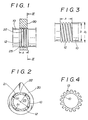
- the shaft 10 has a fitting area A on which the cam piece 20 is fitted.
- the area is provided on the outer periphery thereof with a plurality of peripherally extending protrusions 12 in the form of an annular-groove knurling.
- the protrusions are previously formed by rolling for fitting engagement with the chordal inner surface 22 which is formed in the bore 25 of the cam piece 20 to assemble the cam piece and the shaft into a camshaft.
- the peripheral or helical protrusions in the form of an annular or helical-groove knurling can be formed by means of pressure deformation, for example, by rolling.
- the protrusions extend continuously, peripherally in the form of an annular-groove knurling as seen in FIG. 1.
- the protrusions extend continuously, helically in the form of a helical-groove knurling as seen in FIG. 3.
- the protrusions extend discretely, peripherally or helically in the form of a criss-cross or diamond knurling as seen in FIG. 4,
- the protrusions in the form of a coarse criss-cross or diamond knurling are shaped by knurling.
- the knurled and rolled protrusions are preferable considering an efficiency in production.
- the protrusions 12 have an outer diameter D1 larger than the outer diameter D of the shaft 10 except the fitting area A in which the individual root between the two adjacent protrusions 12 has a diameter smaller than D.
- the bore in the cam piece 20 consists of inner arcuate surfaces 21 and inner chordal surfaces 22 which are alternately, circumferentially connected.
- the arcuate surface 21 has a diameter D2 larger than the diameter D1 of the protrusions 12.
- the chordal surface 22 has such a perpendicular from the center of the bore 25 that is shorter than the radius of the protrusions 12 but longer than the radius of the root between the two adjacent protrusions.
- the bore 25 of FIG. 2 consists of four same arcuate surfaces 21 and four same chordal surfaces 22. It can consists of any number of arcuate or chordal surfaces. Both or either of arcuate and chordal surfaces may be in number more or less than 4. For example, an arcuate surface and a chordal surface can constitute the bore. Furthermore, the bore in the shape of polygon is formed only by the chordal surfaces.
- the polygonal bore makes a tight fitting with the shaft so that there occurs no relative motion between the fitting member and the shaft.
- the chordal surface is easy to be manufactured and finished since it is simple and flat. This results to remarkably reduce the cost of manufacturing the camshaft as compared with the conventional camshaft.
- the cam piece 20 is axially slid onto the fitting area A from an end of the shaft 10. Then, the chordal surface 22 within the bore 25 of the cam piece 20 has its central portion shaving the protrusions 12 partly, the both side portions adjacent to the central portion deforming the same plastically, and the both further side portions deforming the same elastically, so that the cam piece 20 is tightly fitted on the protrusions.
- the cam piece 20 is chamferred at the forward end of the bore 25 and formed with a conical surface 23.
- the conical surface 23 facilitates for the inner chordal surface 22 to form the corresponding outer surface on the protrusions 12 of the shaft 10 in a shaving and/or deforming operation.
- the conical surface 23 also serves as a stopper to determine the axial position of the cam piece on the shaft.
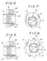
- FIG. 7 There is shown a shaft-supported rotor for use in a rotary compressor in FIG. 7, in which the rotor body 20 in the form of a disk is the fitting member.
- the bore 25 is eccentric to the center of the rotor body 20.
- the shaft 10 has the protrusions 12 formed on the outer surface in the fitting area of the shaft by means of pressure deformation.
- the bore 25 is composed of four inner arcuate surfaces 21 and four inner chordal surfaces 22, alternately connected to each other.
- the diameter D1 of the protrusions 12 is smaller than the diameter D2 of the arcuate surface 21, while the radius of the protrusions 12 is larger than the perpendicular to the chordal surface 22 from the center of the bore 25.
- the shaft-supported rotor has the same longitudinal section as shown in FIG. 1.
- a shaft-supported gear is shown in FIG. 8, in which the spur gear 20 is the fitting member.
- the bore 25 is concentric to the center of the gear 20.
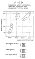
- the fitting members were made from a Fe-8%Cr alloy and had an axial length of 11 mm.
- the shafts were made from a steel similar to SAE 1050.
- the first protrusions extended continuously, axially in the form of axial-groove knurling.
- the second protrusions extended discretely, peripherally or helically in the form of a criss-cross or diamond knurling.
- the third protrusions extended continuously, peripherally in the form of an annular-groove knurling.
- the hexagonal bore had an inscribed circle which was radially smaller by 0.8 mm than the protrusions, so that there was in maximum a radial interference of 0.8 mm between the fitting members and the shafts.
- the test results are shown in FIG.
- Regular hexagonal, octagonal, decagonal and dodecagonal bores in the fitting members were tested by measuring the bonding strength between the fitting members and the shafts after each bore being forced onto the protrusions in the form of the criss-cross knurling on the shaft.
- the polygonal bores had the same circumcircle which was radially larger by 0.8 mm than the protrusions, so that there was in maximum a radial interference between the fitting member and the protrusions.
- the fitting members and the shafts were made from the same materials as those illustrated in FIG 9.
- the test results are shown in FIG. 10 in which the graph illustrates the relation between the angular number of the regular polygonal bores and the bonding strength. From FIG. 10 it is known that the polygonal bores with an angular number of 8 to 10 are superior in bonding strength or applicable torque to the hexagonal and dodecagonal bores.
Claims (8)
dadurch gekennzeichnet, daß
zumindest eine innere Oberfläche der Bohrung eine sehnenförmige Oberfläche ist.
Applications Claiming Priority (2)
| Application Number | Priority Date | Filing Date | Title |
|---|---|---|---|
| JP31143190 | 1990-11-19 | ||
| JP311431/90 | 1990-11-19 |
Publications (4)
| Publication Number | Publication Date |
|---|---|
| EP0486876A2 EP0486876A2 (de) | 1992-05-27 |
| EP0486876A3 EP0486876A3 (en) | 1992-09-16 |
| EP0486876B1 true EP0486876B1 (de) | 1994-09-14 |
| EP0486876B2 EP0486876B2 (de) | 1998-12-30 |
Family
ID=18017127
Family Applications (1)
| Application Number | Title | Priority Date | Filing Date |
|---|---|---|---|
| EP91118912A Expired - Lifetime EP0486876B2 (de) | 1990-11-19 | 1991-11-06 | Maschinenelement mit mindestens einem mit Druck auf einer Welle befestigten Verbindungsteil |
Country Status (3)
| Country | Link |
|---|---|
| US (2) | US5419217A (de) |
| EP (1) | EP0486876B2 (de) |
| DE (1) | DE69104016T3 (de) |
Cited By (1)
| Publication number | Priority date | Publication date | Assignee | Title |
|---|---|---|---|---|
| CN104379882A (zh) * | 2012-07-18 | 2015-02-25 | 马勒国际有限公司 | 凸轮轴 |
Families Citing this family (49)
| Publication number | Priority date | Publication date | Assignee | Title |
|---|---|---|---|---|
| US5909980A (en) * | 1995-01-26 | 1999-06-08 | Barsplice Products, Inc. | Tubular coupler for concrete reinforcing bars |
| DE19608983A1 (de) * | 1995-03-17 | 1996-09-19 | Volkswagen Ag | Steuerwelle und Verfahren zu ihrer Herstellung |
| US5682641A (en) * | 1995-06-29 | 1997-11-04 | Robert D. Newman, Sr. | Tool handle with locking assembly |
| WO1997022819A1 (en) * | 1995-12-15 | 1997-06-26 | Zenith Sintered Products, Inc. | Duplex sprocket/gear construction and method of making same |
| DE19625554C2 (de) * | 1996-06-26 | 1999-07-29 | Hans Dipl Ing Kuehl | Verfahren und Einrichtung zum drehfesten Verbinden einer Welle mit mindestens einem auf der Welle angeordnetem Teil |
| JP3450970B2 (ja) * | 1996-10-17 | 2003-09-29 | アスモ株式会社 | ワイヤハーネス接続部の防水具 |
| EP0866216B1 (de) | 1997-03-21 | 2003-05-07 | Stefan Battlogg | Nockenwelle |
| JPH1136831A (ja) * | 1997-07-18 | 1999-02-09 | Toyota Motor Corp | 三次元カムシャフト及びその製造方法 |
| DE19925028A1 (de) * | 1999-06-01 | 2000-12-21 | Thyssen Krupp Automotive Ag | Nocken für zusammengesetzte Nockenwelle |
| US6375381B1 (en) * | 2000-01-06 | 2002-04-23 | Curtiss Wright Flight Systems, Inc. | Machine element/assembly and magneform joint |
| IL135744A (en) * | 2000-04-18 | 2008-08-07 | Mosaid Technologies Inc | Telephone communication system through a single line |
| DE10027517A1 (de) * | 2000-06-06 | 2001-12-13 | Thyssen Krupp Automotive Ag | Einrichtung mit einer Welle und mit zumindest einer auf dieser Welle angebrachten Nabe und Verfahren für die Herstellung dieser Einrichtung |
| JP3820347B2 (ja) * | 2000-12-28 | 2006-09-13 | 本田技研工業株式会社 | カム組立体およびカム位置決め装置 |
| JP2002307237A (ja) * | 2001-04-09 | 2002-10-23 | Harmonic Drive Syst Ind Co Ltd | 波動歯車装置の剛性内歯歯車の製造方法 |
| US6682250B2 (en) | 2001-11-07 | 2004-01-27 | Lockheed Martin Corporation | Position-adjustable fastening apparatus and method |
| DE60306150T2 (de) * | 2002-05-01 | 2007-04-19 | Ultimate Design Solutions Ltd. | Verbindungsvorrichtung |
| JP2004195567A (ja) * | 2002-12-16 | 2004-07-15 | Denso Corp | 圧入材、整流素子の圧入方法および整流装置 |
| JP2005040842A (ja) * | 2003-07-24 | 2005-02-17 | Uk:Kk | 中空段付軸の成形方法 |
| DE602004009087T2 (de) * | 2003-08-27 | 2008-06-12 | Gen Tek Technologies Marketing, Inc., Parsipanny | Verfahren zur herstellung einer nocken-eingriffs-kurbelschwinge |
| EP1553329B1 (de) * | 2004-01-12 | 2007-01-03 | Robert Bürgler | Anordnung und Verfahren zum Herstellen einer Nockenwelle |
| JP4731497B2 (ja) * | 2004-02-06 | 2011-07-27 | メルツ,カール | カムシャフトとその製造方法 |
| US20070271985A1 (en) * | 2004-08-26 | 2007-11-29 | Gentek Technologies Marketing Inc. | Method for Forming a Cam-Engaged Rocker Arm |
| DE202005000430U1 (de) * | 2005-01-13 | 2006-05-24 | Brose Fahrzeugteile Gmbh & Co. Kommanditgesellschaft, Coburg | Befestigung eines Getriebeelementes in einem Kraftfahrzeug |
| JP2006234437A (ja) * | 2005-02-22 | 2006-09-07 | Seiko Instruments Inc | 歯車構造体及びこれを備えた時計 |
| WO2007077880A1 (ja) * | 2005-12-28 | 2007-07-12 | Nippon Piston Ring Co., Ltd. | 焼結部品が接合された軸部材の製造方法、および内燃機関用カムシャフト |
| DE102006012358A1 (de) * | 2006-03-17 | 2007-09-27 | Mahle International Gmbh | Verfahren zur Erzeugung einer Pressverbindung |
| US20070247015A1 (en) * | 2006-04-25 | 2007-10-25 | A. O. Smith Corporation | Rotor having lobed bore and method of assembling same |
| CN101153599B (zh) * | 2006-09-28 | 2010-07-28 | 株式会社神户制钢所 | 螺旋转子 |
| GB0619741D0 (en) * | 2006-10-06 | 2006-11-15 | Rolls Royce Plc | Mounting arrangement |
| US20080172979A1 (en) * | 2007-01-19 | 2008-07-24 | Wilson Eric J | Reinforcing bar splice with cutting edge bolts |
| DE102007018920B3 (de) * | 2007-04-19 | 2008-08-28 | Thyssenkrupp Presta Ag | Antriebswelle |
| GB0807778D0 (en) * | 2008-04-29 | 2008-06-04 | Romax Technology Ltd | Apparatus and method for improving radial stresses in a gear transmission mounting |
| DE202009000623U1 (de) * | 2009-01-15 | 2009-03-19 | Acument Gmbh & Co. Ohg | Profile zur Übertragung von Drehmomenten und drehmomentschlüssige Verbindung |
| DE102010048225B4 (de) * | 2010-10-12 | 2021-03-18 | Neumayer Tekfor Engineering Gmbh | Fertigung einer Funktionswelle |
| DE102012207271A1 (de) * | 2012-05-02 | 2013-11-07 | Robert Bosch Gmbh | Verfahren zum Verbinden einer Welle mit einem Rotationsbauteil und nach diesem Verfahren hergestellte Turboladerwelle |
| DE102012223811A1 (de) * | 2012-12-19 | 2014-06-26 | Mahle International Gmbh | Nockenwelle |
| CN205456047U (zh) * | 2013-05-08 | 2016-08-17 | 吉瑞高新科技股份有限公司 | 电子烟连接座及电子烟雾化器 |
| CN203457808U (zh) * | 2013-08-23 | 2014-03-05 | 刘秋明 | 雾化组件、电池组件以及电子烟 |
| CH709379A1 (de) | 2014-03-11 | 2015-09-15 | Unipart Ag | Vorrichtung und Verfahren zur Herstellung einer Funktionswelle. |
| CN106352619B (zh) * | 2015-07-14 | 2020-05-12 | 株式会社不二工机 | 储存器 |
| DE102015224574A1 (de) | 2015-12-08 | 2017-06-08 | Bayerische Motoren Werke Aktiengesellschaft | Rotor, Verfahren zum Herstellen eines Rotors, Asynchronmaschine und Fahrzeug |
| DE102015224577A1 (de) | 2015-12-08 | 2017-06-08 | Bayerische Motoren Werke Aktiengesellschaft | Rotor, Verfahren zum Herstellen eines Rotors, Asynchronmaschine und Fahrzeug |
| DE102015224579A1 (de) * | 2015-12-08 | 2017-06-08 | Bayerische Motoren Werke Aktiengesellschaft | Rotor, Verfahren zum Herstellen eines Rotors, Asynchronmaschine und Fahrzeug |
| DE102016208968A1 (de) * | 2016-05-24 | 2017-11-30 | Thyssenkrupp Ag | Schiebemodul einer Nockenwelle |
| JP6717711B2 (ja) | 2016-08-30 | 2020-07-01 | ファナック株式会社 | 電磁ブレーキ |
| US9759098B1 (en) | 2016-09-09 | 2017-09-12 | William Cullen Chapman, Jr. | Valvetrain conversion kit for an engine |
| US10487932B2 (en) * | 2016-11-30 | 2019-11-26 | GM Global Technology Operations LLC | Vehicle differential |
| DE102017108373A1 (de) * | 2017-04-20 | 2018-08-16 | Schaeffler Technologies AG & Co. KG | Wankstabilisator für ein Kraftfahrzeug |
| IT201800003230A1 (it) * | 2018-03-02 | 2019-09-02 | Ge Avio Srl | Ingranaggio non-assialsimmetrico |
Family Cites Families (15)
| Publication number | Priority date | Publication date | Assignee | Title |
|---|---|---|---|---|
| DE2336241A1 (de) * | 1973-07-17 | 1975-02-06 | Volkswagenwerk Ag | Poly-metallische, zusammengefuegte steuerwellen |
| US4006993A (en) * | 1975-11-25 | 1977-02-08 | Borg-Warner Corporation | Shaft mounting arrangement |
| JPS5891311A (ja) * | 1981-11-24 | 1983-05-31 | Toyota Motor Corp | カムシヤフト |
| DE3401057A1 (de) * | 1983-01-14 | 1984-07-19 | Kokan Kako Co., Ltd., Yokohama, Kanagawa | Verfahren zur verbindung eines rohrfoermigen teils mit einem ringfoermigen teil |
| US4597365A (en) * | 1985-02-07 | 1986-07-01 | General Motors Corporation | Camshaft assembly and method |
| JPH0121192Y2 (de) * | 1985-06-07 | 1989-06-23 | ||
| JPS62199907A (ja) * | 1986-02-28 | 1987-09-03 | Mazda Motor Corp | エンジンのカムシヤフト |
| JPS62248808A (ja) * | 1986-04-22 | 1987-10-29 | Musashi Seimitsu Ind Co Ltd | 組立カムシヤフト |
| DE3704092C1 (de) * | 1987-02-10 | 1988-05-26 | Schneider Gesenkschmiede | Hohlwelle sowie Verfahren zu ihrer Herstellung |
| CA1290596C (en) * | 1987-03-09 | 1991-10-15 | Philip D. Arnold | Tubular camshaft assemblies, method and apparatus |
| DE3717190A1 (de) * | 1987-05-22 | 1988-12-15 | Supervis Ets | Nockenwelle zur steuerung von ventilen bei verbrennungskraftmaschinen und verfahren zu ihrer herstellung |
| GB8720052D0 (en) * | 1987-08-25 | 1987-09-30 | Jaguar Cars | Cam mechanisms |
| DE8805679U1 (de) * | 1988-04-29 | 1988-06-09 | Kasper, Guenter, 5439 Bad Marienberg, De | |
| JP3163505B2 (ja) * | 1991-06-07 | 2001-05-08 | 日本ピストンリング株式会社 | シャフトを嵌合部材に圧入してなる機械要素及びその製造方法 |
| US5419365A (en) * | 1993-12-16 | 1995-05-30 | J. Edward Stachowiak | Pressure regulator for water blasting |
-
1991
- 1991-11-06 DE DE69104016T patent/DE69104016T3/de not_active Expired - Fee Related
- 1991-11-06 EP EP91118912A patent/EP0486876B2/de not_active Expired - Lifetime
-
1993
- 1993-06-29 US US08/083,323 patent/US5419217A/en not_active Expired - Lifetime
-
1995
- 1995-03-03 US US08/397,931 patent/US5598631A/en not_active Expired - Lifetime
Cited By (2)
| Publication number | Priority date | Publication date | Assignee | Title |
|---|---|---|---|---|
| CN104379882A (zh) * | 2012-07-18 | 2015-02-25 | 马勒国际有限公司 | 凸轮轴 |
| CN104379882B (zh) * | 2012-07-18 | 2016-12-14 | 马勒国际有限公司 | 凸轮轴 |
Also Published As
| Publication number | Publication date |
|---|---|
| EP0486876A3 (en) | 1992-09-16 |
| EP0486876A2 (de) | 1992-05-27 |
| EP0486876B2 (de) | 1998-12-30 |
| DE69104016T3 (de) | 1999-09-02 |
| DE69104016T2 (de) | 1995-01-26 |
| DE69104016D1 (de) | 1994-10-20 |
| US5419217A (en) | 1995-05-30 |
| US5598631A (en) | 1997-02-04 |
Similar Documents
| Publication | Publication Date | Title |
|---|---|---|
| EP0486876B1 (de) | Maschinenelement mit mindestens einem mit Druck auf einer Welle befestigten Verbindungsteil | |
| US4903543A (en) | Camshaft for controlling valves in internal combustion engines and method of manufacturing the camshaft | |
| US5272930A (en) | Mechanical element having a shaft pressure-fitted into an engaging member and its manufacturing method | |
| EP0650550B1 (de) | Nockenwelle und deren herstellungsverfahren | |
| US5307708A (en) | Camshaft for controlling valves in internal combustion engines | |
| EP0282166B1 (de) | Zusammengefügte Nockenwellen. | |
| US5607358A (en) | Connection between inner joint part and driveshaft | |
| US5469759A (en) | Camshaft and method of making a camshaft | |
| EP1653099B1 (de) | Kraftübertragungsmechanismus für welle und nabe | |
| JPS5926805B2 (ja) | 軸部品への嵌合部材の固定法 | |
| US4781075A (en) | Camshaft and method of making the same | |
| EP1653100B1 (de) | Kraftübertragungsmechanismus für welle und nabe | |
| JP3189058B2 (ja) | 嵌合部材にシャフトを圧入してなる機械要素及びその製造方法 | |
| US4809831A (en) | One-way sprag clutch and assembly method of sprags in retainer | |
| WO1995035434A1 (en) | Assembled camshaft | |
| CN107435687B (zh) | 包括耦接接口的可旋转组件 | |
| US6464058B2 (en) | Hub for a clutch | |
| US5855053A (en) | Method and forming die for fabricating spiral groove torque tube assemblies | |
| JP2747537B2 (ja) | カムシャフト | |
| DE102017121135A1 (de) | Verfahren zur Montage zumindest eines Kupplungsbolzens in einer Kupplungsanordnung für ein Wellgetriebe, Kupplungsanordnung für ein Wellgetriebe und Kupplungsbolzen zur Verwendung in einer Kupplungsanordnung für ein Wellgetriebe | |
| JP3292216B2 (ja) | エンジン用カム軸の製造方法 | |
| JPH07238978A (ja) | 回転伝達軸の連結構造 | |
| JPH04365907A (ja) | カムシャフトの製造方法 | |
| CN115750727A (zh) | 降噪齿轮及发动机 | |
| JPH07189614A (ja) | カムシャフト |
Legal Events
| Date | Code | Title | Description |
|---|---|---|---|
| PUAI | Public reference made under article 153(3) epc to a published international application that has entered the european phase |
Free format text: ORIGINAL CODE: 0009012 |
|
| AK | Designated contracting states |
Kind code of ref document: A2 Designated state(s): DE FR GB IT |
|
| PUAL | Search report despatched |
Free format text: ORIGINAL CODE: 0009013 |
|
| AK | Designated contracting states |
Kind code of ref document: A3 Designated state(s): DE FR GB IT |
|
| 17P | Request for examination filed |
Effective date: 19920828 |
|
| 17Q | First examination report despatched |
Effective date: 19921023 |
|
| GRAA | (expected) grant |
Free format text: ORIGINAL CODE: 0009210 |
|
| AK | Designated contracting states |
Kind code of ref document: B1 Designated state(s): DE FR GB IT |
|
| ITF | It: translation for a ep patent filed |
Owner name: JACOBACCI CASETTA & PERANI S.P.A. |
|
| REF | Corresponds to: |
Ref document number: 69104016 Country of ref document: DE Date of ref document: 19941020 |
|
| ET | Fr: translation filed | ||
| PLBI | Opposition filed |
Free format text: ORIGINAL CODE: 0009260 |
|
| 26 | Opposition filed |
Opponent name: ETABLISSEMENT SUPERVIS Effective date: 19950607 |
|
| PLBF | Reply of patent proprietor to notice(s) of opposition |
Free format text: ORIGINAL CODE: EPIDOS OBSO |
|
| PLBO | Opposition rejected |
Free format text: ORIGINAL CODE: EPIDOS REJO |
|
| APAC | Appeal dossier modified |
Free format text: ORIGINAL CODE: EPIDOS NOAPO |
|
| APAE | Appeal reference modified |
Free format text: ORIGINAL CODE: EPIDOS REFNO |
|
| APAC | Appeal dossier modified |
Free format text: ORIGINAL CODE: EPIDOS NOAPO |
|
| PLAW | Interlocutory decision in opposition |
Free format text: ORIGINAL CODE: EPIDOS IDOP |
|
| PUAH | Patent maintained in amended form |
Free format text: ORIGINAL CODE: 0009272 |
|
| STAA | Information on the status of an ep patent application or granted ep patent |
Free format text: STATUS: PATENT MAINTAINED AS AMENDED |
|
| 27A | Patent maintained in amended form |
Effective date: 19981230 |
|
| AK | Designated contracting states |
Kind code of ref document: B2 Designated state(s): DE FR GB IT |
|
| ITF | It: translation for a ep patent filed |
Owner name: JACOBACCI & PERANI S.P.A. |
|
| ET3 | Fr: translation filed ** decision concerning opposition | ||
| REG | Reference to a national code |
Ref country code: GB Ref legal event code: IF02 |
|
| APAH | Appeal reference modified |
Free format text: ORIGINAL CODE: EPIDOSCREFNO |
|
| PGFP | Annual fee paid to national office [announced via postgrant information from national office to epo] |
Ref country code: DE Payment date: 20081103 Year of fee payment: 18 |
|
| PGFP | Annual fee paid to national office [announced via postgrant information from national office to epo] |
Ref country code: IT Payment date: 20081126 Year of fee payment: 18 |
|
| PGFP | Annual fee paid to national office [announced via postgrant information from national office to epo] |
Ref country code: FR Payment date: 20081112 Year of fee payment: 18 |
|
| PGFP | Annual fee paid to national office [announced via postgrant information from national office to epo] |
Ref country code: GB Payment date: 20081105 Year of fee payment: 18 |
|
| GBPC | Gb: european patent ceased through non-payment of renewal fee |
Effective date: 20091106 |
|
| REG | Reference to a national code |
Ref country code: FR Ref legal event code: ST Effective date: 20100730 |
|
| PG25 | Lapsed in a contracting state [announced via postgrant information from national office to epo] |
Ref country code: FR Free format text: LAPSE BECAUSE OF NON-PAYMENT OF DUE FEES Effective date: 20091130 |
|
| PG25 | Lapsed in a contracting state [announced via postgrant information from national office to epo] |
Ref country code: DE Free format text: LAPSE BECAUSE OF NON-PAYMENT OF DUE FEES Effective date: 20100601 |
|
| PG25 | Lapsed in a contracting state [announced via postgrant information from national office to epo] |
Ref country code: GB Free format text: LAPSE BECAUSE OF NON-PAYMENT OF DUE FEES Effective date: 20091106 |
|
| PG25 | Lapsed in a contracting state [announced via postgrant information from national office to epo] |
Ref country code: IT Free format text: LAPSE BECAUSE OF NON-PAYMENT OF DUE FEES Effective date: 20091106 |