EP0486053B1 - Vehicle for cleaning beaches - Google Patents
Vehicle for cleaning beaches Download PDFInfo
- Publication number
- EP0486053B1 EP0486053B1 EP91119542A EP91119542A EP0486053B1 EP 0486053 B1 EP0486053 B1 EP 0486053B1 EP 91119542 A EP91119542 A EP 91119542A EP 91119542 A EP91119542 A EP 91119542A EP 0486053 B1 EP0486053 B1 EP 0486053B1
- Authority
- EP
- European Patent Office
- Prior art keywords
- vehicle according
- rotor
- pickup
- chassis
- rubbish
- Prior art date
- Legal status (The legal status is an assumption and is not a legal conclusion. Google has not performed a legal analysis and makes no representation as to the accuracy of the status listed.)
- Expired - Lifetime
Links
Images


Classifications
-
- E—FIXED CONSTRUCTIONS
- E01—CONSTRUCTION OF ROADS, RAILWAYS, OR BRIDGES
- E01H—STREET CLEANING; CLEANING OF PERMANENT WAYS; CLEANING BEACHES; DISPERSING OR PREVENTING FOG IN GENERAL CLEANING STREET OR RAILWAY FURNITURE OR TUNNEL WALLS
- E01H12/00—Cleaning beaches or sandboxes
Definitions
- the invention relates to a vehicle for beach cleaning with a vehicle frame, at least one wheel axle arranged thereon, with a height-adjustable waste pickup, a adjoining latter, the waste taken over from the waste pickup to a conveyor arranged at the rear end of the vehicle frame (such as from the EP -A-0 387794) and a feed rotor assigned to the feed area of the garbage collector.
- Such a beach cleaning vehicle is also known from US-A-4,482,019.
- waste from the ground is z.
- B. a sandy beach and transferred to a conveyor belt.
- the tines of the feed rotor are curved at their ends in the direction of travel, the rotor rotates in the same direction.
- the speed of rotation of the rotor is added to the driving speed in the receiving area, so that the waste is thrown tangentially forward in the direction of travel when it comes into contact with the tines. In this way, contaminants can accumulate in front of the feed rotor and impair further use.
- the tines are heavily loaded when they hit the dirt or sand due to the high relative speed and can break.
- Fibrous impurities such as algae can wrap around the feed rotor and the sinks and become matted with them due to the rotation of the feed rotor and the long entrainment until delivery to the conveyor belt.
- the known feed rotor must frequently be cleaned and freed from the algae.
- the entire vehicle frame with all the devices attached to it is lowered.
- the wheels mounted on a bracket-shaped bracket are pivoted backwards by an actuating device and the entire vehicle is thereby lowered.
- a height adjustment of the feed rotor relative to the conveyor belt is not possible.
- the distance between the feed rotor and the conveyor belt cannot be varied. Bulky impurities cannot be picked up and may damage the vehicle.
- a separation of impurities and sand takes place in the previously known beach vehicle only with the help of a sieve belt arranged after the conveyor belt. It must have both the contaminants and the sand transport. This can put a heavy load on the vehicle, particularly in the case of damp sand.
- part of the sand with the impurities is transported to the collection container. The collection container is filled prematurely and must be exchanged for another container or emptied.
- the invention has for its object to provide a vehicle for beach cleaning of the type mentioned, which is improved when feeding, picking up and transporting waste and when separating the waste from the sand and when disposing of the contaminants.
- a swivel frame carrying the garbage collector and the feed rotor for height adjustment is lowered on the vehicle frame, on which the feed rotor by means of a handlebar over a different operating positions swiveling range from the front is pivotally mounted to the rear and can be rotated, in particular counterclockwise, about a horizontal axis of rotation mounted on the links.
- the feed rotor is arranged in a first, front operating position for feeding garbage and / or sand to the waste pickup in the direction of travel in front of a receiving wedge strip arranged at the front of the waste pickup, in a second, middle operating position the distance between the receiving wedge strip and the feed rotor is minimal and in one In the third, rear operating position, the feed rotor is arranged at a greater distance from the receiving wedge strip or from the waste pickup above compared to the second operating position.
- the waste pick-up is lowered down to or into the sand with the holding wedge strip.
- the impurities and possibly sand are absorbed via the wedge ledge.
- the feed rotor is also lowered. Since this is pivotably mounted relative to the waste pickup, both the distance from the feed rotor to the waste pickup or wedge bar and the height of the feed rotor relative to the sand can be varied independently of the waste pickup.
- the feed rotor In a first operating position, the feed rotor is arranged in the direction of travel in front of the wedge bar and thus also in front of the waste collector. If in this position the wedge bar rests roughly on the sand, the feed rotor rotates above the sand or penetrates the sand surface only slightly. In this position, the feed rotor feeds all surface contaminants to the waste collector. Only a small amount of sand is taken up and therefore a high driving speed is possible. In addition, since the rotor rotates counterclockwise, the rotation speed and the vehicle speed do not add up, which leads to a lower load on the rotor. This throws the impurities in the direction of the wedge ledge and garbage collector, at the same time a partial separation of the contamination occurs depending on its weight. Lighter impurities are thrown further towards the waste collector than heavier ones, e.g. B. sand.
- Any impurities not detected by the feed rotor are subsequently removed by the Wedge ledge picked up and passed on to the waste collector. In this way, all debris is absorbed by the beach up to a certain immersion depth and this is cleaned intensively.
- the first operating position is particularly advantageous in the case of wet sand or in the flood zone area, since only a small amount of sand is absorbed and the surface is cleaned thoroughly.
- the second operating position of the feed rotor is preferably used.
- the rotor not only serves to supply contaminants to the waste collector, but also to accelerate the sand and the contaminants taken up by the wedge bar.
- the wedge bar is partially immersed in the sand.
- the feed rotor forming a channel with the wedge ledge partly covers the sand and in particular the garbage lying superficially on the sand. Similar to the first operating position, the rotor throws the materials in its rotating area towards the waste collector. The lighter parts are thrown further than the heavier parts. In this way, sand and impurities are already partially fed to the waste collector and are easier to separate from each other on this. At the same time, the accelerated forwarding of the materials picked up enables a higher driving speed.
- the wedge bar can recorded parts are carried out in the gap formed between the rotor and the wedge bar to the waste collector.
- the rotation of the rotor supports further transport.
- claims 2 and 3 are also advantageous, since in this way the swivel frame is of simple design and is arranged completely below the vehicle frame.
- the top of the vehicle frame can also be used in a variety of ways, such as. B. for transporting building material, soil, nursery items or the like.
- the swivel frame itself can be lowered by the storage at its rear end with its end lying in the direction of travel. At this end feed rotor and wedge bar are arranged.
- claims 4 and 5 are advantageous in that a versatile use of the vehicle is possible in this way.
- the swivel frame can be exchanged together with the waste pick-up and feed rotor with the help of detachable quick-release fasteners for another swivel frame with corresponding devices. Converting the vehicle to other areas of application is possible without spending a lot of time. This increases the flexibility of the vehicle. For example, use for cleaning asphalt roads is also possible, in which case the receiving wedge strip is preferably elastic and the feed rotor is designed in particular as a brush roller is.
- the vehicle can also be used for general transport without a swivel frame.
- claims 6 to 9 are also advantageous, since in this way the refuse collector can be used for many areas of application.
- the contaminants are taken over by the elevator from the feed rotor or the wedge ledge and passed on to the downstream conveyor. If the elevator has its own drive, its speed can be set independently of the speed of rotation of the feed rotor or the speed of the conveyor and can be easily adapted to applications with different amounts of waste.
- the construction of the vehicle according to claims 10 to 12 is also favorable.
- the draw-in area of the wedge ledge, feed rotor and garbage collector can be designed according to the vehicle width.
- the width of the waste stream is reduced in accordance with the specified conditions via the arranged side coulters and guide plates and is thus, for. B. between the wheels attached to the wheel axle.
- the contaminants are absorbed before they are possibly compacted with the wheels of the vehicle or even pressed into the ground, and the sand is cleaned across the entire width of the vehicle.
- a larger width would be z. B. the wedge bar possible, but this would complicate the handling of the vehicle and people may be injured by the ends of the wedge bar protruding laterally from the vehicle contour.
- the features of the protection claims 13 and 14 are advantageous in that with the help of the adjusting device e.g. B. automatically controlled lowering and lifting of the swivel frame is possible.
- the actuating device can be designed as a hydraulic actuating cylinder and z. B. be operated remotely by the driver of the vehicle.
- the adjusting device is arranged on the side of the frame.
- the angle of incidence relative to the garbage pickup of the receiving wedge strip is greater than the angle of incidence of the garbage pickup. In this way, in the second operating position between the receiving wedge strip and the feed rotor, a narrowing transport channel is obtained for the further transport of waste and sand that has been taken in, the end of the transport channel having a larger opening angle and the material taken up thereby being better distributed over the waste collector.
- the rotor is thus easily accessible.
- the arrangement of the flange bearings and bearing brackets makes it very easy to swivel over the swivel range encompassing the operating positions.
- the swivel radius of the feed rotor is relatively large, and yet it is possible to swivel the swivel frame close to the vehicle frame, with flange bearings and bearing brackets of the rotor being arranged laterally next to the vehicle frame. Due to the special bearing of the rotor axis of rotation, a fine height adjustment of the rotor is also possible.
- a drive device is assigned to one end of the rotor axis of rotation.
- This can be a hydraulic motor that is connected to the hydraulic system of the vehicle and can be adjusted by the driver if necessary.
- claims 23 and 24 are also advantageous, since the actuating device for pivoting the rotor allows it to be pivoted independently of the waste pickup.
- the actuator can, for. B. be designed as a hydraulically actuated piston. So that no greater leverage occurs, the Actuator attached with one end close to the rotor axis of rotation. In order to further facilitate the pivoting, the other end of the adjusting device is arranged on a side wall of the impact cladding.
- the feed rotor has a plurality of radially projecting tines which determine the rotor circumference. With the help of the tines, the impurities or the sand are thrown in the direction of the wedge ledge or the waste collector.
- the tines can be designed as elastic tines made of metal or plastic which are fixedly arranged on the axis of rotation of the rotor. It is also possible to store the tines spring loaded.
- the receiving wedge bar extends in the direction of travel essentially in a direction parallel to a tangent of a pivoting curve, the pivot curve being determined as the envelope of a part of the rotor circumference lying opposite the pivot bearing.
- a deflection axis can be designed as an unbalanced shaft on the conveyor as well as on the garbage collector and can make shaking off the sand or the soil material easier by means of a targeted oscillating movement that runs vertically to the transport direction.
- the front cross member of the vehicle frame laterally protrudes beyond the longitudinal members to approximately the vehicle width and the actuating devices are supported at its ends.
- tipping devices for a loading area arranged on the vehicle frame can also be mounted at these ends.
- the vehicle frame is essentially formed by a frame rectangle formed by two long beams and two cross beams and a frame triangle arranged at its front end.
- a coupling device for a towing vehicle is arranged at the top of the frame triangle.
- the collecting container can be pivoted over the leather surface by means of two supports arranged on the side of the vehicle frame or on the leather surface and can be emptied evenly onto the leather surface.
- the features of the protection claims 35 to 37 are advantageous in that with the aid of the rocker arms, a uniform pouring out of the collecting container is possible over the entire length of the loading area.
- the first garbage is placed over a pouring edge of the collecting container emptied onto the loading area directly above the rear end and gradually pivoted further by the arrangement of the tilting link and carrier of the collecting container during the pivoting to the front end of the loading area.
- Due to the triangular connection frame the carrier of the collecting container can be rotated from a substantially horizontal position into an approximately vertical position with the aid of a tilting device.
- Both the tilting device for the collecting container and the tilting device for the loading area can be designed as hydraulically actuated pistons.
- a further development of the vehicle according to claims 38 to 40 is also expedient.
- a height adjustment of the rear end of the vehicle is possible due to the wheel axle designed as a lift axle.
- the vehicle frame is raised with the aid of the lifting device and the collected garbage can also be tipped into a higher container.
- FIG. 1 the vehicle according to the invention for beach cleaning 1 is shown together with a towing vehicle 2.
- the beach cleaning vehicle 1 is connected to the latter by means of a coupling device 3 and a coupling device 77 formed on the towing vehicle 2 and is movable over a base 68.
- the vehicle 1 is essentially from the Vehicle frame 4, a folded-up loading area 5, a swiveling frame 7 arranged under the vehicle frame 4 and a collecting container 6 pivoted over the loading area 5 are formed.
- the coupling device 3 is arranged on the vehicle frame 4 at its front end and an essentially horizontal tilting axis 51 for the loading area 5 is arranged at its rear end.
- the loading area 5 is pivoted upward about 45 ° relative to the vehicle frame 4 about the tilt axis 51.
- an adjustable rear wall 50 which is pivotably mounted at the rear upper end of the loading area 5, is partially open.
- a collecting container swiveling device 39 is arranged on a side wall 87 of the loading area near the underside facing the vehicle frame. This runs essentially parallel and closely adjacent to the underside of the side surface 87.
- the pivoting device 39 is mounted on the side surface 87 at a front end 40, while the rear end 41 is mounted on the tip of a triangular frame element 48, 49.
- the ends of the legs 48 and 49 of the triangular frame element are connected to a carrier 42.
- This and the triangle legs enclose an essentially equilateral triangle.
- the triangular leg 48 and the carrier 42 In the vicinity of the connection between the triangular leg 48 and the carrier 42, the latter is pivotably mounted on the underside of the side wall 87 of the loading surface 5 at its end 43.
- the collecting container 6 At the opposite end 44, the collecting container 6 is pivotably mounted relative to the carrier 42.
- the end 44 of the carrier 42 is arranged approximately in the center of gravity of a side surface of the collecting container 6.
- a cross member 45 extends at right angles to the carrier 42 along the collecting container 6.
- a rocker arm 46 is rotatably mounted on the side wall 87 of the loading surface 5 adjacent to the end 43 of the carrier 42.
- the bearing point 164 of the rocker arm 46 is shown in FIGS. 2 and 3 and is offset relative to the bearing point 43 of the support 42 in the direction of the upper edge of the side wall 87.
- the rocker arm 46 is rotatably mounted on the collecting container 6. This end lies essentially offset on a straight line which runs vertically to the bottom surface and runs through the end point 44 of the carrier 42 in the direction of the top of the collecting container 6.
- the rocker arm 46 is formed with a somewhat shorter length than the carrier 42.
- a loading surface tipping device 36 which is arranged between a cross member 35 of the frame 4 and the side surface 87 of the loading surface 5, the latter is pivoted relative to the vehicle frame 4.
- the tilting device 36 is rotatably supported at one end 37 on the cross member 35 and is arranged at the other end 38 approximately above the end 43 of the carrier 42 in the center of the side wall 87.
- an actuating device 32 Opposite the end 37 of the tilting device 36, an actuating device 32 with one end 34 is rotatably mounted on the cross member 35. With its other end 33, it is rotatably mounted on a swivel frame 7 arranged below the vehicle frame 4.
- the swivel frame 7 can be lowered in the direction of the floor 68 about an essentially horizontal swivel axis 8 arranged in the vicinity of its rear end.
- a number of rollers 20, 21, 24, 25, 26, 27 and 28 are rotatably mounted in the swivel frame 7.
- the rollers 20 and 21 serve as deflection axes for a conveyor belt formed from upper run 22 and lower run 23.
- the rollers 24, 25 and 26 are designed as support rollers and, together with the deflection axes 20 and 21, define a transport plane of the upper strand 22.
- the rollers 27 and 28 are each arranged between the deflection axes 20 and 21 and the support rollers 24 and 26 adjacent to them.
- rollers 27 and 28 serve as tensioning rollers and are arranged below the lower run 23 and guide it in the direction of the upper run 22.
- the lower run 23 between the tensioning rollers 27 and 28 sags in the direction of the bottom 68.
- a baffle cover 15 is arranged on the swivel frame 7 above the deflection axis 20 and the support roller 24. This points from the swivel frame 7 in the direction of the vehicle frame 4.
- a cover 16 of the impact lining 15 with the underside of the vehicle frame 4 is in contact over its entire length.
- the end 33 of the actuating device 32 is arranged near the swivel frame 7.
- a guide plate 65 which extends in the longitudinal direction of the swivel frame and extends above the upper run 22.
- an adjusting device 29 extends between a rear upper edge of the impact cladding 15 and a feed rotor 11 arranged in front of it. It is mounted at its rear end 31 on the impact cladding 15 and at its front end 30 on the feed rotor 11.
- the feed rotor 11 is rotatable about an axis of rotation 18. It has a plurality of radially projecting tines 67.
- a drive device cover 17 extends between the axis of rotation 18 and the vehicle frame 4. This partially projects laterally beyond the vehicle frame 4.
- a bearing bracket 19 is directed toward the upper end of the cover 17. This is arranged on a front edge of the cover 16 of the impact lining 15.
- a side sheet 64 partially covering this laterally is arranged as an extension of the swivel frame 7.
- the height of the side coulter 64 corresponds approximately to the height of the end of the swivel frame 7 that is adjacent to it above, wherein it runs approximately parallel to the opposite end of the swivel frame 7 pointing towards a conveyor 12.
- the conveyor 12 is arranged between the wheel axle 13 and the vehicle frame 4. It has an inclination essentially corresponding to the swivel frame.
- the transport direction of the conveyor 12 and of the waste pickup 9 arranged in the swivel frame 7 is the same and in the direction of the rear end of the vehicle 1 directed. Similar to the swivel frame 7, the conveyor 12 also has side-guiding plates 66.
- FIG. 1 the vehicle frame 4 is shown lifted relative to the wheel axle 13.
- Two support arms 62 and 63 connected to the vehicle frame 4 point from the vehicle frame in the direction of the wheel axis 13.
- a lifting cylinder 61 is arranged centrally between them.
- a lifting piston 60 is almost completely extended from the lifting cylinder 61, with a holding part 59 partially encompassing the wheel axle 13 being arranged at its end. This has a cross section similar to an isosceles triangle.
- the reciprocating piston 60 is connected in the center to the base of this triangle.
- a height-adjustable adjusting wheel 162 for parking the vehicle 1 is arranged near the coupling device 3 perpendicular to the vehicle frame 4.
- FIG. 2 shows the beach cleaning vehicle 1 with the pivot frame 7 lowered to the floor 68.
- the same parts are provided with the same reference numerals as in FIG. 1 and are only mentioned in part.
- the loading area 5 is placed on the vehicle frame 4 in this figure.
- the tilting device 36 moves its end 38 along the circular arc 72, the loading surface 5 assuming approximately the position shown in FIG. 1 at the end of the circular arc.
- the tip 41 of the triangular frame part can be guided along the semicircular arc 71 with the aid of the collecting container swiveling device 39.
- the position of the collecting container 6 shown which is pivoted as far as possible over the loading surface 5 and the triangular tip 41 points in the direction of the pivoting device 39, is in the position of the collecting container 6 shown in FIG. 2, this near the bottom 68 below the rear deflection axis 53 the conveyor 12 arranged.
- the center area 44 of the collecting container 6 moves along the circle 69 to the position of the collecting container 6 '.
- the end point 47 of the rocker arm 46 moves along the arch 70. Due to the relative arrangement and length of the carrier 42 and the rocker arm 46 described in FIG. 1, the corresponding guide arch 69 and 70 intersect and the open end of the collecting container 6 is more and more pointed Direction of the loading area 5 and can be emptied via a pouring edge 161 in the direction of the loading area 5.
- the swivel frame 7 is lowered around the laying point 8 at one end to the floor 68.
- a receiving wedge strip 10 arranged below the feed rotor 11 on the swivel frame 7 touches the bottom 68 with its free end, and the side sheet 64 runs with its underside essentially parallel to the bottom.
- the beach cleaning vehicle 1 is shown in a plan view.
- the vehicle frame 4 has a triangular frame section connected to the coupling device 3 and a rectangular section section adjoining this.
- the triangular frame section is formed by two supports 81 and 82 running symmetrically to the longitudinal direction 100 of the coupling device 3 in the direction of a first cross member 35.
- the triangular tip is arranged in the coupling device 3, while the triangular base is formed by the cross member 35.
- Parallel to the longitudinal axis 100 are connected to the beams 81 and 82, longitudinal beams 75 and 76.
- the rectangular frame section is formed by these beams, the cross beam 35 and a cross beam 78 arranged near the vehicle end.
- the longitudinal members 75 and 76 are at a distance corresponding to the distance between the wheels 14 and 14 '.
- the loading surface 5 is pivotally mounted, these ends projecting beyond the cross member 78 to the rear.
- the cross member 78 extends from one longitudinal member to the other, the longitudinal member 35 parallel to the latter has a greater length. With its ends 79 and 80, it protrudes on both sides of the side members by the same length in each case.
- the actuators 32 and 36 are pivotally mounted.
- the loading area 5 is arranged lying thereon.
- a front wall 88, two side walls 87 and 89 and a rear wall 50 can be seen from the loading area 5.
- the side walls or front and rear walls are parallel to the longitudinal beams 75 and 76 or cross beams 35 and 78 and form the rectangular loading area 5.
- the rear wall 50 runs, as shown in FIG. 2, at an angle to the vertical towards the rear toward the collecting container 6. While the upper edge of the rear wall 50 is arranged in front of the collecting container, the lower edge closer to the collecting container is arranged above an opening 90 of the collecting container 6.
- the pouring edge 161 is thus located below the loading area 5.
- the pouring edge and its opposite side of the collecting container run essentially parallel to the rear wall 50.
- the extent of the collecting container 6 perpendicular to the longitudinal direction 100, ie its width, is slightly shorter than the inner distance between the side walls 87 and 89 of the loading area.
- the collecting container 6 is connected in the center via the bearings 44 and 44 'or 47 and 47' to the carrier 42 and 42 'or the rocker arms 46 and 46'.
- the brackets 42 and 42 ' run parallel to the rocker arms 46 and 46' outside the side walls 87 and 89.
- both the brackets 42 and the rocker arms 46 are with the side wall 87 and correspondingly on the other side with the side wall 89 connected.
- the pivoting device 39 runs between a first bearing point 40 and a second bearing point 41. This is above the carrier 42 according to FIG. 1 and 2 designed as a triangular tip.
- the distance from the carrier 42 and the collecting container swiveling device 39 to the side wall 87 is essentially the same. The same applies to the collecting container swiveling device 39 'on the other side wall 89 of the loading area 5.
- a hydraulic cover 91 is arranged on the triangular frame section formed by the supports 81 and 82. This extends symmetrically to the longitudinal direction 100, with its side surfaces running essentially parallel to and projecting above the supports 81 and 82.
- the cover 16 is arranged symmetrically to the longitudinal direction 100. On both sides, it protrudes somewhat relative to the side walls 87 and 89 of the loading area 5, the adjusting devices 29 and 29 'being arranged on these sides.
- the distance between these adjusting devices essentially corresponds to the distance between the collecting container pivoting devices 39 and 39 'or the distance between the supports 42 and 42'.
- bearing tabs 19 and 19 ' are arranged symmetrically to the longitudinal direction. These are in engagement with bearing devices 85 and 86 of a frame 84.
- the frame 84 runs parallel to the front of the cover 16 and projects beyond it laterally through two arms directed in the direction of the adjusting devices 29 and 29 '.
- the drive device cover 17 is arranged on one side of the frame 84, with a motor 83 protruding from the cover 17 in the direction of the longitudinal axis of the frame 84.
- the beach cleaning vehicle 1 is shown in a plan view of the garbage collector 9, the conveyor 12 and the collecting container 6.
- Both the run 22 of the garbage collector 9 and the run 58 of the conveyor 12 are designed as sieve belts. These have a plurality of essentially diamond-shaped openings.
- two side coulters 64 and 64 ′ which are angled outward symmetrically to the longitudinal direction 100, are arranged at the ends of the wedge strip 10.
- the receiving width 92 of the side coulters 64 and 64 ' essentially corresponds to the vehicle width 93.
- the wedge ledge 10 protrudes from the waste pickup 9 approximately over half the longitudinal extent of the side coulters 64 and 64' in the direction of the coupling device 3.
- Adjoining plates 96 and 97 running on both sides symmetrically to the longitudinal direction 100 adjoin these ends.
- a drive device 98 is arranged on one side on the rear deflection axis 21. At least the support rollers 25 and 26 are drive-connected to the deflection axis 21 by drive connections 99.
- the conveyor 12 also has an output device 101 arranged on one side on its rear deflection axis 53.
- the frame 84 is essentially U-shaped.
- a U-web 103 runs horizontally and parallel to the rotor pivot axis 120 or rotor rotation axis 18. At its ends, the U-web 103 has U-legs 104 and 105 arranged at right angles to this. These extend to almost above a rotor shaft 106 which is concentric with the axis of rotation 18.
- Bearing flanges 107 and 108 are arranged at the ends 109 and 110 of the U-legs 104 and 105. These are placed on the U-legs 104 and 105 from the outside and connected to them.
- the axis of rotation 18 is mounted in the bearing flanges 107 and 108.
- Concentric rotor end disks 132 and 133 are arranged on the axis of rotation 18. These limit the feed rotor 11 in the direction of the axis of rotation.
- a plurality of radially projecting tines 67 are arranged on the rotor shaft 106. For clarification, only a few tines are shown in FIG. 5.
- Bearing devices 85 and 86 are arranged on the U-web 103 for mounting the feed rotor 11 on the swivel axis 120. These are each formed by a pair of bearing flanges 116, 117 and 118, 119. The bearing flanges have a corresponding opening to accommodate the swivel axis.
- a drive device 111 is arranged on one side of the feed rotor 11. This comprises a motor 112 arranged above the U-web 103 and a drive pulley 113 mounted on its drive axle. This is connected via a V-belt 115 to a drive pulley 114 arranged coaxially on the axis of rotation.
- FIG. 6 shows a side view, in particular of the flange stop 108.
- This is essentially U-shaped.
- elongated holes 123 and 124 are arranged symmetrically to an elongated groove receiving the axis of rotation.
- a U-leg has a thickening in which a bore 30 is arranged.
- One end of the actuating device 29 can be stored in this bore.
- a U-leg 105 of the frame 84 from FIG. 5 is visible above the bearing flange 108. Both the longitudinal groove 122 and the U-leg 105 extend vertically in the direction 125. At the upper end of the U-leg 105, the bearing flange 119 runs in the direction 126. This has at its free end a pivot bearing bore 121. Angle 127 is included between direction 125 of longitudinal groove 122 and direction 126 of bearing flange 119.
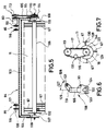
- FIG. 7 shows the drive device of the feed rotor 11.
- the rotor end disk 133 is arranged concentrically to the axis of rotation 18. Tines 67 protrude radially from these and fix the circumferential line 129 when rotated in the direction 128.
- the drive pulley 114 is connected to it coaxially with the axis of rotation 18.
- the drive pulley 113 connected to the motor is arranged vertically above this drive pulley. Both are connected to the drive via a V-belt 115.
- a tensioning roller 131 For tensioning the V-belt, a tensioning roller 131, which is offset laterally to the connecting line of these two, is arranged between the drive pulleys 113 and 114.
- the feed rotor 11 is pivoted forward about the pivot bearing axis 120 with the aid of the adjusting device 29.
- the deepest point of the feed rotor 11 is located near the surface 68 and in front of the receiving wedge strip 10.
- the tines 67 engage in a layer of waste 136 lying on the surface when rotated counterclockwise 128. Both by rotating the feed rotor 11 and by moving the vehicle in the direction 140, the waste 136 is conveyed onto the upper run 22 of the waste receiver via the receiving wedge strip 10. This transports the garbage in the direction of 137.
- the receiving wedge strip 10 In the operating position shown in FIG. 8, the receiving wedge strip 10 is arranged near the surface 68 but above it.
- the feed rotor 11 can be pivoted forwards with the aid of the adjusting device 29 until the length of the piston 138 corresponds approximately to the length of the adjusting device 29. In the position of the feed rotor pivoted furthest back, the piston 138 is completely retracted into the actuating device 29. The entire swivel range of the feed rotor corresponds essentially to the swivel arc 74 of the axis of rotation 18.
- a wedge-shaped recess 139 is arranged in a side wall 134 of the impact lining 15. This serves to receive the axis of rotation 18 when the feed rotor 11 is pivoted.
- FIG. 9 shows a second operating position of the feed rotor 11.
- the receiving wedge ledge 144 is inserted into the sand 135 to the depth d.
- Both sand 135 and waste 136 are arranged between the receiving wedge strip 10 and the feed rotor 11.
- the feed rotor 11 is pivoted so far to the rear that the distance e between the circumferential line 129 and the wedge strip 10 is minimal.
- Other characteristic sizes according to the Invention are the distance a from the tip 144 of the receiving wedge strip 10 and the perpendicular base 143 of the solder 142 placed by the pivot axis 120, and the distance b and c of the pivot axis 120 from the vertical base and from the plane formed by the receiving wedge strip 10.
- the receiving wedge strip forms an angle ⁇ with the horizontal which is larger by the angle 145 than the angle ⁇ enclosed between the upper strand 22 and the horizontal.
- the feed rotor 11 is shown in a third operating position.
- the piston 138 is fully inserted into the actuating device 29 and the feed rotor is arranged in its most pivoted rearward position. In this position, its peripheral line 129 almost touches the cover 16 from below and the axis of rotation 18 is inserted as far as possible into the cutout 139 of the side wall of the impact cladding.
- circumferential line 129 and upper run 22 are arranged at a distance f.
- the distance f is approximately twice the distance e between the circumferential line and the receiving wedge strip 10 in the second operating position.
- the distance e is the minimum distance.
- FIG. 11 shows the wheel axle 13 in a front view.
- a bottom wall 146 of the loading area 5 runs horizontally and lies on the cross member 78 of the vehicle frame. This is laterally enclosed by long beams 75 and 76.
- the loading area 5 in Side walls 82 and 87 enclosing the vertical direction are arranged above the longitudinal beams 75, 76 and offset to the outside thereof.
- the lifting cylinders are arranged directly below the longitudinal beams 75 and 76 and, like these, are arranged symmetrically to the central vertical axis 164 of the vehicle.
- Lower lifter mounts 149 and 150 are formed on each of the support members.
- the reciprocating pistons movable in the lifting cylinders are mounted on these. Above the lower lifting device fasteners 149 and 150, the ends of the lifting pistons 61 and 61 'are passed through lifting piston guides 147 and 148.
- the lifting device is shown in a side view.
- the upper lifting device mounting 153 is visible below the longitudinal beam 76.
- This is essentially formed by a profile arranged laterally on it parallel to the longitudinal beam 76.
- a hole 154 for supporting the upper end of the lifting cylinder 61 is formed in the center of this profile.
- Two support arms 62 and 63 pointing in the direction of the wheel axis are arranged on the longitudinal member 76 at the ends of the profile.
- a profile 148 for fixing the lower end of the lifting cylinder 61 is attached between the free ends of the support arms.
- the lifting cylinder 61 itself runs centrally to the support arms 62 and 63 which essentially enclose a triangle with the longitudinal beam 76. Below the In the illustration according to FIG.
- the profile 148 is arranged directly at the lower bearing point of the lifting device.
- the holding part 59 is shown abutting them. In cross section, this essentially has the shape of an isosceles triangle.
- the free ends of the support arms 62 and 63 abut the ends of the base line of this triangle.
- the lower bearing point 150 of the lifting device is arranged centrally between these free ends in the middle of the base line.
- the two legs of the triangle point in the direction of the wheel axis 13 and partially encompass them.
- FIG. 13 shows the lifting device with the lifting piston 60 extended to the maximum.
- the same reference numerals designate the same parts as in FIG. This is only partially addressed.
- the longitudinal member 76 is shown lifted upwards by the distance g with respect to the wheel axle 13.
- the free ends 157 and 158 of the support arms 62 and 63 have journals 155 and 156. These are arranged parallel to the lifting cylinder 61 or reciprocating piston 60 and point to the holding part 59.
- Corresponding bearing openings 159 and 160 are arranged in this, which in the illustration according to FIG. 12 are in engagement with the bearing pins 155 and 156.
Landscapes
- Engineering & Computer Science (AREA)
- Architecture (AREA)
- Civil Engineering (AREA)
- Structural Engineering (AREA)
- Cleaning Of Streets, Tracks, Or Beaches (AREA)
- Refuse-Collection Vehicles (AREA)
Description
Die Erfindung betrifft ein Fahrzeug zur Strandreinigung mit einem Fahrzeugrahmen, wenigstens einer an diesem angeordneten Radachse, mit einem höhenverstellbaren Müllaufnehmer, einem an diesen anschließenden, den vom Müllaufnehmer übernommenen Müll an einen am hinteren Ende des Fahrzeugrahmens angeordneten Sammelbehälter überführenden Förderer(wie z.B. aus der EP-A-0 387794 vorbekannt) und einem dem Einzugsbereich des Müllaufnehmers zugeordneten Zuführrotor.The invention relates to a vehicle for beach cleaning with a vehicle frame, at least one wheel axle arranged thereon, with a height-adjustable waste pickup, a adjoining latter, the waste taken over from the waste pickup to a conveyor arranged at the rear end of the vehicle frame (such as from the EP -A-0 387794) and a feed rotor assigned to the feed area of the garbage collector.
Ein solches Strandreinigungsfahrzeug ist auch aus der US-A-4 482 019 bekannt. Von einem mit Zinken ausgebildeten Zuführrotor wird Abfall vom Untergrund z. B. eines Sandstrandes aufgenommen und auf ein Förderband überführt. Die Zinken des Zuführrotors sind an Ihren Enden in Fahrtrichtung gekrümmt, der Rotor dreht sich in die gleiche Richtung.Such a beach cleaning vehicle is also known from US-A-4,482,019. From a feed rotor formed with prongs, waste from the ground is z. B. a sandy beach and transferred to a conveyor belt. The tines of the feed rotor are curved at their ends in the direction of travel, the rotor rotates in the same direction.
Nachteilig daran ist, daß die Verunreinigungen in Fahrtrichtung vom Untergrund aufgenommen und zumindest über einen Bereich von 180o über den Zuführrotor hinweggeführt werden müssen. Von den Zinken nach vorne weggeschleuderte Verunreinigungen prallen teilweise an ein Rotorgehäuse, teilweise fallen sie zurück auf den Strand, geraten dadurch wieder vor den Zuführrotor und müssen neu aufgenommen werden.A disadvantage that the impurities must be included in the driving direction from the substrate and at least passed over a range of 180 o about the feed rotor. Contaminants thrown forward by the tines partially hit a rotor housing, sometimes fall back onto the beach, get back in front of the feed rotor and have to be taken up again.
Die Umdrehungsgeschwindigkeit des Rotors addiert sich im Aufnahmebereich zur Fahrgeschwindigkeit, so daß der Abfall beim Kontakt mit den Zinken tangential in Fahrtrichtung nach vorne geschleudert wird. Auf diese Weise können sich Verunreinigungen vermehrt vor dem Zuführrotor ansammeln und einen weiteren Einsatz beeinträchtigen.The speed of rotation of the rotor is added to the driving speed in the receiving area, so that the waste is thrown tangentially forward in the direction of travel when it comes into contact with the tines. In this way, contaminants can accumulate in front of the feed rotor and impair further use.
Die Zinken sind beim Auftreffen auf die Verunreinigungen bzw. den Sand durch die hohe Relativgeschwindigkeit stark belastet und können brechen.The tines are heavily loaded when they hit the dirt or sand due to the high relative speed and can break.
Faserige Verunreinigungen wie Algen, können sich durch die Drehung des Zuführrotors und die lange Mitnahme bis zur Abgabe an das Transportband um den Zuführrotor und die Sinken wickeln und mit diesen verfilzen. Bei verstärkter Algenverunreinigung muß der bekannte Zuführrotor häufig gereinigt und von den Algen befreit werden.Fibrous impurities such as algae can wrap around the feed rotor and the sinks and become matted with them due to the rotation of the feed rotor and the long entrainment until delivery to the conveyor belt. In the case of increased algae contamination, the known feed rotor must frequently be cleaned and freed from the algae.
Durch die Ausbildung des Zuführrotors und dessen Zuordnung zum Transportband werden nur Verunreinigungen vom Strand aufgenommen, die der Rotor erfaßt. Nicht vom Zuführrotor aufgenommene Verunreinigungen können nicht mehr vom Transportband aufgenommen werden und verbleiben auf dem Strand.Due to the formation of the feed rotor and its assignment to the conveyor belt, only impurities that the rotor detects are absorbed by the beach. Contaminants not picked up by the feed rotor can no longer be picked up by the conveyor belt and remain on the beach.
Zur Höhenverstellung des Zuführrotors wird der gesamte Fahrzeugrahmen mit allen daran befestigten Einrichtungen abgesenkt. Die an einer bügelförmigen Halterung gelagerten Räder werden durch eine Stelleinrichtung nach hinten verschwenkt und dadurch das gesamte Fahrzeug abgesenkt. Eine Höhenverstellung des Zuführrotors relativ zum Transportband ist nicht möglich. Ebenso ist der Abstand zwischen Zuführrotor und Transportband nicht variierbar. Sperrige Verunreinigungen können gar nicht aufgenommen werden und führen gegebenenfalls zu einer Beschädigung des Fahrzeugs.To adjust the height of the feed rotor, the entire vehicle frame with all the devices attached to it is lowered. The wheels mounted on a bracket-shaped bracket are pivoted backwards by an actuating device and the entire vehicle is thereby lowered. A height adjustment of the feed rotor relative to the conveyor belt is not possible. The distance between the feed rotor and the conveyor belt cannot be varied. Bulky impurities cannot be picked up and may damage the vehicle.
Eine Trennung von Verunreinigungen und Sand findet bei dem vorbekannten Strandfahrzeug erst mit Hilfe eines dem Transportband nachgeordneten Siebbandes statt. Es muß sowohl die Verunreinigungen als auch den Sand transportieren. Dies kann insbesondere bei feuchtem Sand das Fahrzeug gewichtsmäßig stark belasten. Außerdem wird ein Teil des Sandes mit den Verunreinigungen bis zum Sammelbehälter weitertransportiert. Der Sammelbehälter ist vorzeitig gefüllt und muß gegen einen anderen Behälter ausgetauscht oder entleert werden.A separation of impurities and sand takes place in the previously known beach vehicle only with the help of a sieve belt arranged after the conveyor belt. It must have both the contaminants and the sand transport. This can put a heavy load on the vehicle, particularly in the case of damp sand. In addition, part of the sand with the impurities is transported to the collection container. The collection container is filled prematurely and must be exchanged for another container or emptied.
Der Erfindung liegt die Aufgabe zugrunde, ein Fahrzeug zur Strandreinigung der eingangs genannten Art zu schaffen, das beim Zuführen, Aufnehmen und Transportieren von Abfall und beim Trennen des Abfalls vom Sand und beim Entsorgen der Verunreinigungen verbessert ist.The invention has for its object to provide a vehicle for beach cleaning of the type mentioned, which is improved when feeding, picking up and transporting waste and when separating the waste from the sand and when disposing of the contaminants.
Diese Aufgabe wird bei einem Fahrzeug zur Strandreinigung mit den Merkmalen des Oberbegriffs des Anspruches 1 dadurch gelöst, daß ein den Müllaufnehmer und den Zuführrotor tragender Schwenkrahmen zur Höhenverstellung absenkbar am Fahrzeugrahmen gelagert ist, an diesem der Zuführrotor mittels Lenker über einen verschiedene Betriebsstellungen umfassenden Schwenkbereich von vorne nach hinten oben verschwenkbar gelagert ist und um eine an den Lenkern gelagerte horizontale Drehachse insbesondere entgegen des Uhrzeigersinns drehbar ist.This object is achieved in a vehicle for beach cleaning with the features of the preamble of claim 1 in that a swivel frame carrying the garbage collector and the feed rotor for height adjustment is lowered on the vehicle frame, on which the feed rotor by means of a handlebar over a different operating positions swiveling range from the front is pivotally mounted to the rear and can be rotated, in particular counterclockwise, about a horizontal axis of rotation mounted on the links.
Dabei ist der Zuführrotor in einer ersten, vorderen Betriebsstellung zum Zuführen von Müll und/oder Sand zum Müllaufnehmer in Fahrtrichtung vor einer vorne am Müllaufnehmer angeordneten Aufnahmekeilleiste angeordnet, in einer zweiten, mittleren Betriebsstellung ist der Abstand zwischen der Aufnahmekeilleiste und dem Zuführrotor minimal und in einer dritten, hinteren Betriebsstellung ist der Züführrotor in einem im Vergleich zur zweiten Betriebsstellung größeren Abstand zur Aufnahmekeilleiste bzw. zum Müllaufnehmer oberhalb angeordnet.The feed rotor is arranged in a first, front operating position for feeding garbage and / or sand to the waste pickup in the direction of travel in front of a receiving wedge strip arranged at the front of the waste pickup, in a second, middle operating position the distance between the receiving wedge strip and the feed rotor is minimal and in one In the third, rear operating position, the feed rotor is arranged at a greater distance from the receiving wedge strip or from the waste pickup above compared to the second operating position.
Gemäß der Erfindung muß daher nicht der gesamte Fahrzeugrahmen zur Höhenverstellung des Müllaufnehmers abgesenkt werden, sondern nur der Schwenkrahmen. Der Müllaufnehmer wird je nach Einsatz mit der Aufnahmekeilleiste bis auf den Sand bzw. in den Sand hinein abgesenkt. Über die Keilleiste werden die Verunreinigungen und eventuell Sand aufgenommen. Gleichzeitig wird auch der Zuführrotor mit abgesenkt. Da dieser relativ zum Müllaufnehmer verschwenkbar gelagert ist, ist sowohl der Abstand von Zuführrotor zu Müllaufnehmer bzw. Keilleiste und die Höhe des Zuführrotors relativ zum Sand unabhängig vom Müllaufnehmer variierbar.According to the invention, therefore, it is not necessary to lower the entire vehicle frame for height adjustment of the garbage collector, but only the swivel frame. Depending on the application, the waste pick-up is lowered down to or into the sand with the holding wedge strip. The impurities and possibly sand are absorbed via the wedge ledge. At the same time, the feed rotor is also lowered. Since this is pivotably mounted relative to the waste pickup, both the distance from the feed rotor to the waste pickup or wedge bar and the height of the feed rotor relative to the sand can be varied independently of the waste pickup.
In einer ersten Betriebsstellung ist der Zuführrotor in Fahrtrichtung vor der Keilleiste und damit auch vor dem Müllaufnehmer angeordnet. Wenn in dieser Stellung die Keilleiste in etwa auf dem Sand aufliegt, dreht sich der Zuführrotor oberhalb des Sandes bzw. dringt nur wenig in die Sandoberfläche ein. In dieser Stellung führt der Zuführrotor alle oberflächlichen Verunreinigungen dem Müllaufnehmer zu. Es findet nur eine geringe Sandaufnahme statt und daher ist eine hohe Fahrtgeschwindigkeit möglich. Da sich außerdem der Rotor im Gegenuhrzeigersinn dreht, addieren sich Rotationsgeschwindigkeit und Fahrgeschwindigkeit nicht, was zu einer geringeren Belastung des Rotors führt. Dieser schleudert die Verunreinigungen in Richtung Keilleiste und Müllaufnehmer, wobei gleichzeitig eine teilweise Trennung der Verunreinigung in Abhängigkeit ihres Gewichtes auftritt. Leichtere Verunreinigungen werden weiter in Richtung des Müllaufnehmers geschleudert als schwerere, z. B. Sand.In a first operating position, the feed rotor is arranged in the direction of travel in front of the wedge bar and thus also in front of the waste collector. If in this position the wedge bar rests roughly on the sand, the feed rotor rotates above the sand or penetrates the sand surface only slightly. In this position, the feed rotor feeds all surface contaminants to the waste collector. Only a small amount of sand is taken up and therefore a high driving speed is possible. In addition, since the rotor rotates counterclockwise, the rotation speed and the vehicle speed do not add up, which leads to a lower load on the rotor. This throws the impurities in the direction of the wedge ledge and garbage collector, at the same time a partial separation of the contamination occurs depending on its weight. Lighter impurities are thrown further towards the waste collector than heavier ones, e.g. B. sand.
Eventuell von dem Zuführrotor nicht erfaßte Verunreinigungen werden nachträglich noch von der Keilleiste aufgenommen und an den Müllaufnehmer weitergeführt. Auf diese Weise werden bis zu einer gewissen Eintauchtiefe alle Verunreinigungen vom Strand aufgenommen und dieser intensiv gesäubert.Any impurities not detected by the feed rotor are subsequently removed by the Wedge ledge picked up and passed on to the waste collector. In this way, all debris is absorbed by the beach up to a certain immersion depth and this is cleaned intensively.
Die erste Betriebsstellung ist insbesondere bei nassem Sand bzw. im Flutsaumbereich von Vorteil, da nur eine geringe Sandaufnahme erfolgt und die Oberfläche gründlich gereinigt wird.The first operating position is particularly advantageous in the case of wet sand or in the flood zone area, since only a small amount of sand is absorbed and the surface is cleaned thoroughly.
Bei trockenem Sand wird vorzugsweise die zweite Betriebsstellung des Zuführrotors benutzt. In dieser Stellung dient der Rotor nicht nur zum Zuführen von Verunreinigungen zum Müllaufnehmer, sondern auch zum Beschleunigen des von der Keilleiste aufgenommenen Sandes und der Verunreinigungen. Die Keilleiste ist hierbei teilweise in den Sand eingetaucht. Der mit der Keilleiste einen Kanal bildende Zuführrotor erfaßt sowohl teilweise den Sand als insbesondere den oberflächlich auf dem Sand liegenden Müll. Ähnlich wie bei der ersten Betriebsstellung schleudert der Rotor die in seinem Drehbereich befindlichen Materialien in Richtung des Müllaufnehmers. Die leichteren Teile werden weiter als die schwereren Teile geschleudert. Auf diese Weise werden Sand und Verunreinigungen schon teilweise getrennt dem Müllaufnehmer zugeführt und sind auf diesem umso leichter weiter voneinander zu trennen. Gleichzeitig ist durch die beschleunigte Weiterführung der aufgenommenen Materialien eine höhere Fahrgeschwindigkeit möglich.In the case of dry sand, the second operating position of the feed rotor is preferably used. In this position, the rotor not only serves to supply contaminants to the waste collector, but also to accelerate the sand and the contaminants taken up by the wedge bar. The wedge bar is partially immersed in the sand. The feed rotor forming a channel with the wedge ledge partly covers the sand and in particular the garbage lying superficially on the sand. Similar to the first operating position, the rotor throws the materials in its rotating area towards the waste collector. The lighter parts are thrown further than the heavier parts. In this way, sand and impurities are already partially fed to the waste collector and are easier to separate from each other on this. At the same time, the accelerated forwarding of the materials picked up enables a higher driving speed.
In der dritten Betriebsstellung ist es insbesondere möglich, auch sperrige Teile aufzunehmen. Da der Abstand zwischen Zuführrotor und Keilleiste bzw. Müllaufnehmer relativ groß ist, können die durch die Keilleiste aufgenommene Teile in dem zwischen Rotor und Keilleiste gebildeten Spalt zum Müllaufnehmer durchgeführt werden. Der Rotor unterstützt durch seine Drehung den Weitertransport.In the third operating position, it is particularly possible to accommodate bulky parts. Since the distance between the feed rotor and the wedge bar or garbage collector is relatively large, the wedge bar can recorded parts are carried out in the gap formed between the rotor and the wedge bar to the waste collector. The rotation of the rotor supports further transport.
Die sowohl durch Zuführrotor als auch Müllaufnehmer schon zum großen Teil vom Sand getrennten Verunreinigungen werden auf dem anschließenden Förderer nahezu vollständig von eventuell mittransportiertem Sand befreit und dem Sammelbehälter zugeführt.The contaminants, which are largely separated from the sand by the feed rotor and the waste pickup, are almost completely freed of any sand that may have been transported on the subsequent conveyor and fed to the collecting container.
Günstig sind ferner die Merkmale der Ansprüche 2 und 3, da auf diese Weise der Schwenkrahmen einfach ausgebildet und vollständig unterhalb des Fahrzeugrahmens angeordnet ist. Die Oberseite des Fahrzeugrahmens kann zusätzlich vielfältig genutzt werden, wie z. B. zum Transportieren von Baumaterial, Erdreich, Gärtnereiartikeln oder dergleichen. Der Schwenkrahmen selbst ist durch die Lagerung an seinem hinteren Ende mit seinem in Fahrtrichtung liegenden Ende absenkbar. An diesem Ende sind Zuführrotor und Aufnahmekeilleiste angeordnet.The features of
Die Merkmale der Schutzansprüche 4 und 5 sind insofern vorteilhaft, als auf diese Weise ein vielfältiger Einsatz des Fahrzeuges möglich ist. Der Schwenkrahmen kann zusammen mit Müllaufnehmer und Zuführrotor mit Hilfe lösbarer Schnellverschlüsse gegen einen anderen Schwenkrahmen mit entsprechenden Einrichtungen ausgetauscht werden. Ein Umrüsten des Fahrzeuges auf anderen Einsatzgebiete ist ohne großen Zeitaufwand möglich. Die Flexibilität des Fahrzeugs wird dadurch erhöht. Z. B. ist auch ein Einsatz zur Reinigung von asphaltierten Straßen möglich, wobei in diesem Fall die Aufnahmekeilleiste vorzugsweise elastisch und der Zuführrotor insbesondere als Bürstenrolle ausgebildet ist. Ebenso ist das Fahrzeug auch ohne Schwenkrahmen zum allgemeinen Transport einsetzbar.The features of
Vorteilhaft sind auch die Merkmale der Ansprüche 6 bis 9, da auf diese Weise der Müllaufnehmer für viele Einsatzgebiete verwendbar ist. Die Verunreinigungen werden von dem Elevator vom Zuführrotor bzw. der Keilleiste übernommen und an den nachgeordneten Förderer weitergeführt. Falls der Elevator über einen eigenen Antrieb verfügt, ist dessen Geschwindigkeit unabhängig von der Drehgeschwindigkeit des Zuführrotors bzw. der Geschwindigkeit des Förderers einstellbar und an Einsätze mit unterschiedlichem Müllaufkommen leicht anpaßbar.The features of
Günstig ist auch die Ausbildung des Fahrzeuges gemäß der Ansprüche 10 bis 12. Der Einzugsbereich von Keilleiste, Zuführrotor und Müllaufnehmer kann entsprechend der Fahrzeugbreite ausgebildet sein. Über die angeordneten Seitenschare und Einweisbleche wird die Breite des Müllstromes entsprechend der vorgegebenen Bedingungen verkleinert und ist so z. B. zwischen den an der Radachse angebrachten Rädern durchführbar. Die Verunreinigungen werden bevor sie mit den Rädern des Fahrzeuges möglicherweise verdichtet oder gar in den Untergrund eingedrückt werden, aufgenommen und der Sand über die gesamte Fahrzeugbreite gereinigt. Prinzipiell wäre auch eine größere Breite z. B. der Keilleiste möglich, dies würde aber die Handhabung des Fahrzeuges erschweren und durch die aus der Fahrzeugkontur seitlich hervorstehenden Enden der Keilleiste werden möglicherweise Personen verletzt.The construction of the vehicle according to
Die Merkmale der Schutzansprüche 13 und 14 sind insofern vorteilhaft, als mit Hilfe der Stelleinrichtung ein z. B. automatisch gesteuertes Absenken und Anheben des Schwenkrahmens möglich ist. Die Stelleinrichtung kann als hydraulischer Stellzylinder ausgebildet sein und z. B. vom Fahrer des Fahrzeuges fernbedient werden. Um die gesamte Breite des Schwenkrahmens für den Müllaufnehmer nutzen zu können, ist die Stelleinrichtung seitlich an den Rahmen angeordnet.The features of the protection claims 13 and 14 are advantageous in that with the help of the adjusting device e.g. B. automatically controlled lowering and lifting of the swivel frame is possible. The actuating device can be designed as a hydraulic actuating cylinder and z. B. be operated remotely by the driver of the vehicle. In order to be able to use the entire width of the swivel frame for the refuse collector, the adjusting device is arranged on the side of the frame.
Weiterhin ist es günstig, wenn der Anstellwinkel zur Müllaufnanme der Aufnahmekeilleiste relativ zum Boden größer ist als der Anstellwinkel des Müllaufnehmers. Auf diese Weise erhält man in der zweiten Betriebsstellung zwischen Aufnahmekeilleiste und Zuführrotor einen sich verengenden Transportkanal zum Weitertransportieren von aufgenommenem Müll und Sand, wobei das Ende des Transportkanals einen größeren Öffnungswinkel aufweist und dadurch das aufgenommene Material besser über den Müllaufnehmer verteilt werden kann.Furthermore, it is advantageous if the angle of incidence relative to the garbage pickup of the receiving wedge strip is greater than the angle of incidence of the garbage pickup. In this way, in the second operating position between the receiving wedge strip and the feed rotor, a narrowing transport channel is obtained for the further transport of waste and sand that has been taken in, the end of the transport channel having a larger opening angle and the material taken up thereby being better distributed over the waste collector.
Außerdem ist eine Weiterbildung des Fahrzeuges gemäß der Schutzansprüche 16 bis 18 zweckmäßig. Mit Hilfe der Prallverkleidung wird eventuell vom Rotor nach oben oder potentiell über den Müllaufnehmer hinausgeschleudertes Material abgefangen und auf den Müllaufnehmer zurückgelenkt. Gleichzeitig werden beim Aufprall z. B. Sandklumpen zerkleinert, was eine nachfolgende Trennung von Müll und Sand auf dem Müllabnehmer bzw. dem Förderer erleichtert. Insbesondere die entgegengesetzt zur Fahrtrichtung abnehmende Höhe der Prallverkleidung verhindert, daß der Müll bzw. Sand über den Müllaufnehmer fortgeschleudert wird. Zusätzlich dient die Abdeckung der Prallverkleidung als Anschlag beim Zurückschwenken des Schwenkrahmens in Richtung des Fahrzeugrahmens und zur Lagerung der Rotorschwenkachse.In addition, a further development of the vehicle according to
Vorteilhafte Ausgestaltungen einer Zuführrotoraufhängung sind in Ansprüchen 19 bis 21 zu entnehmen. Durch die Verwendung des U-förmigen Rahmens ist der Zuführrotor im Prinzip pendelförmig mit Hilfe des Rahmens aufgehängt. Mit Hilfe der vom U-Steg abstehenden Flanschlager und den entsprechenden an der Abdeckung abstehenden Lagerlaschen ist der gesamte Rahmen um die Schwenkachse verschwenkbar.Advantageous embodiments of a feed rotor suspension can be found in
Der Rotor ist somit leicht zugänglich aufgehängt. Außerdem ist durch die Anordnung der Flanschlager und Lagerlaschen in einfachster Weise ein Verschwenken über den die Betriebsstellungen umfassenden Schwenkbereich möglich. Der Schwenkradius des Zuführrotors ist relativ groß, und doch ist es möglich, den Schwenkrahmen bis nah an den Fahrzeugrahmen heranzuschwenken, wobei Flanschlager und Lagerlaschen des Rotors seitlich neben dem Fahrzeugrahmen angeordnet sind. Durch die spezielle Lagerung der Rotordrehachse ist außerdem eine Höhenfeineinstellung des Rotors möglich.The rotor is thus easily accessible. In addition, the arrangement of the flange bearings and bearing brackets makes it very easy to swivel over the swivel range encompassing the operating positions. The swivel radius of the feed rotor is relatively large, and yet it is possible to swivel the swivel frame close to the vehicle frame, with flange bearings and bearing brackets of the rotor being arranged laterally next to the vehicle frame. Due to the special bearing of the rotor axis of rotation, a fine height adjustment of the rotor is also possible.
Um den Zuführrotor unabhängig von anderen Einrichtungen in seiner Rotationsgeschwindigkeit einzustellen, ist es außerdem günstig, wenn einem Ende der Rotordrehachse eine Antriebseinrichtung zugeordnet ist. Dies kann ein Hydromotor sein, der an das Hydrauliksystem des Fahrzeuges angeschlossen, und vom Fahrer gegebenenfalls einstellbar ist.In order to adjust the rotational speed of the feed rotor independently of other devices, it is also advantageous if a drive device is assigned to one end of the rotor axis of rotation. This can be a hydraulic motor that is connected to the hydraulic system of the vehicle and can be adjusted by the driver if necessary.
Vorteilhaft sind auch die Merkmale der Ansprüche 23 und 24, da sich durch die Stelleinrichtung zum Verschwenken des Rotors dieser unabhängig vom Müllaufnehmer verschwenken läßt. Die Stelleinrichtung kann z. B. als hydraulisch betätigbarer Kolben ausgebildet sein. Damit keine größeren Hebelkräfte auftreten, ist die Stelleinrichtung mit einem Ende nahe an der Rotordrehachse befestigt. Um weiterhin das Verschwenken zu erleichtern, ist das andere Ende der Stelleinrichtung an einer Seitenwand der Prallverkleidung angeordnet.The features of
Bei einer vorteilhaften Ausführungsform weist der Zuführrotor eine Vielzahl von radial abstehenden, den Rotorumfang bestimmenden Zinken auf. Mit Hilfe der Zinken werden die Verunreinigungen bzw. der Sand in Richtung der Keilleiste bzw. des Müllaufnehmers geschleudert. Die Zinken können als fest an der Drehachse des Rotors angeordnete elastische Zinken aus Metall oder Kunststoff ausgebildet sein. Ebenso ist es möglich, die Zinken federbeaufschlagt zu lagern.In an advantageous embodiment, the feed rotor has a plurality of radially projecting tines which determine the rotor circumference. With the help of the tines, the impurities or the sand are thrown in the direction of the wedge ledge or the waste collector. The tines can be designed as elastic tines made of metal or plastic which are fixedly arranged on the axis of rotation of the rotor. It is also possible to store the tines spring loaded.
Um in der zweiten Betriebsstellung einen minimalen Abstand zwischen Keilleiste und Rotordrehachse zu erreichen, sowie in dieser Stellung die Transportwirkung des Rotors zu optimieren, ist es von Vorteil, wenn sich die Aufnahmekeilleiste in Fahrtrichtung im wesentlichen in eine Richtung parallel zu einer Tangente einer Verschwenkkurve erstreckt, wobei die Verschwenkkurve als Einhüllende eines dem Schwenklager gegenüberliegenden Teils des Rotorumfanges bestimmt ist.In order to achieve a minimum distance between the wedge bar and the rotor axis of rotation in the second operating position and to optimize the transport effect of the rotor in this position, it is advantageous if the receiving wedge bar extends in the direction of travel essentially in a direction parallel to a tangent of a pivoting curve, the pivot curve being determined as the envelope of a part of the rotor circumference lying opposite the pivot bearing.
Vorteilhafte Anordnungen von Zuführrotor und Keilleiste ergeben sich durch die Merkmale der Ansprüche 27 bis 30.Advantageous arrangements of feed rotor and wedge bar result from the features of
Die Merkmale der Schutzansprüche 31 und 32 sind insofern vorteilhaft, als mit Hilfe des Förderers ein zusätzliches Trennen des Mülls von dem mitgeführten Bodenmaterial möglich ist. Um ein Verschmutzen bzw. Beschädigen der Radachse und sämtlicher unterhalb der Fördereinrichtung angeordneter Leitungen zu verhindern, ist der Einbau eines Prallblechs über der Hinterachse vorteilhaft. An dem Förderer wie aber auch an dem Müllaufnehmer kann eine Umlenkachse als Unwuchtwelle ausgebildet sein und durch eine gezielte, vertikal zur Transportrichtung laufende Schwingbewegung das Abschütteln des Sandes bzw. des Bodenmateriales erleichtern.The features of the protection claims 31 and 32 are advantageous in that an additional separation of the waste from the carried soil material is possible with the aid of the conveyor. In order to prevent contamination or damage to the wheel axle and all lines arranged below the conveyor, a baffle plate must be installed above the rear axle advantageous. A deflection axis can be designed as an unbalanced shaft on the conveyor as well as on the garbage collector and can make shaking off the sand or the soil material easier by means of a targeted oscillating movement that runs vertically to the transport direction.
Zur Lagerung der Stelleinrichtungen des Schwenkrahmens ist es von Vorteil, wenn der vordere Querträger des Fahrzeugrahmens seitlich über die Langsträger bis in etwa zur Fahrzeugbreite übersteht und an seinen Enden die Stelleinrichtungen gelagert sind. Gleichzeitig können an diesen Enden auch Kippeinrichtungen für eine auf dem Fahrzeugrahmen angeordnete Ladefläche gelagert sein. Bei einem Ausführungsbeispiel ist der Fahrzeugrahmen im wesentlichen durch ein durch zwei Langsträger und zwei Querträger gebildetes Rahmenrechteck und ein an dessen vorderem Ende angeordnetes Rahmendreieck gebildet. An der Spitze des Rahmendreiecks ist eine Kupplungseinrichtung für ein Zugfahrzeug angeordnet.To mount the actuating devices of the swivel frame, it is advantageous if the front cross member of the vehicle frame laterally protrudes beyond the longitudinal members to approximately the vehicle width and the actuating devices are supported at its ends. At the same time, tipping devices for a loading area arranged on the vehicle frame can also be mounted at these ends. In one embodiment, the vehicle frame is essentially formed by a frame rectangle formed by two long beams and two cross beams and a frame triangle arranged at its front end. A coupling device for a towing vehicle is arranged at the top of the frame triangle.
Um eine möglichst große Ladefläche zu erhalten, ist es von Vorteil, wenn die Ladefläche sich nahezu vollständig über Müllaufnehmer und Förderer erstreckt. Der Sammelbehälter ist über die Ledefläche durch zwei seitlich am Fahrzeugrahmen oder an der Ledefläche angeordnete Träger verschwenkbar und kann gleichmäßig auf die Ledefläche entleert werden.In order to obtain the largest possible loading area, it is advantageous if the loading area extends almost completely over garbage receptacles and conveyors. The collecting container can be pivoted over the leather surface by means of two supports arranged on the side of the vehicle frame or on the leather surface and can be emptied evenly onto the leather surface.
Außerdem sind die Merkmale der Schutzansprüche 35 bis 37 insofern vorteilhaft, als mit Hilfe der Kipplenker ein gleichmäßiges Ausschütten des Sammelbehälters über die gesamte Länge der Ladefläche möglich ist. Über eine Schüttkante des Sammelbehälters wird der erste Müll direkt oberhalb des hinteren Endes der Ladefläche auf diese entleert und durch die Anordnung von Kipplenker und Träger der Sammelbehälter während des Verschwenkens zum vorderen Ende der Ladefläche allmählich weiter verschwenkt. Durch den dreieckförmigen Anschlußrahmen ist der Träger des Sammelbehälters von einer im wesentlichen horizontalen Stellung in eine in etwa vertikale Stellung mit Hilfe einer Kippeinrichtung drehbar. Sowohl die Kippeinrichtung für den Sammelbehälter als auch die Kippeinrichtung für die Ladefläche können als hydraulisch betätigbare Kolben ausgebildet sein kann.In addition, the features of the protection claims 35 to 37 are advantageous in that with the aid of the rocker arms, a uniform pouring out of the collecting container is possible over the entire length of the loading area. The first garbage is placed over a pouring edge of the collecting container emptied onto the loading area directly above the rear end and gradually pivoted further by the arrangement of the tilting link and carrier of the collecting container during the pivoting to the front end of the loading area. Due to the triangular connection frame, the carrier of the collecting container can be rotated from a substantially horizontal position into an approximately vertical position with the aid of a tilting device. Both the tilting device for the collecting container and the tilting device for the loading area can be designed as hydraulically actuated pistons.
Außerdem ist eine Weiterbildung des Fahrzeugs gemäß der Ansprüche 38 bis 40 zweckmäßig. Durch die als Liftachse ausgebildete Radachse ist eine Höhenverstellung des hinteren Endes des Fahrzeugs möglich. Insbesondere zum Entleeren der Ladefläche wird mit Hilfe Hubeinrichtung der Fahrzeugrahmen angehoben und der gesammelte Müll kann auch in einen höheren Container gekippt werden.A further development of the vehicle according to
Die erfindungsgemäß vorgeschlagenen Lösungen und vorteilhafte Ausführungsbeispiele davon werden im folgenden anhand der in der Zeichnung dargestellten Figuren weiter erläutert und beschrieben.The solutions proposed according to the invention and advantageous exemplary embodiments thereof are further explained and described below with reference to the figures shown in the drawing.
Es zeigen :
- Figur 1 das Fahrzeug zur Strandreinigung in einer Seitenansicht mit verschwenkter Ladefläche und Sammelbehälter;
Figur 2 eine Seitenansicht des Fahrzeugs zur Strandreinigung mit abgesenktem Schwenkrahmen;Figur 3 eine Draufsicht des Fahrzeuges;- Figur 4 eine Draufsicht auf Müllaufnehmer und Förderer;
Figur 5 eine Vorderansicht des Zuführrotors;Figur 6 eine Seitenansicht eines Rahmens zur Legerung des Zuführrotors;Figur 7 eine Seitenansicht einer Antriebseinrichtung des Zuführrotors;Figur 8 eine Seitenansicht einer ersten Betriebsstellung des Zuführrotors;Figur 9 eine Seitenansicht einer zweiten Betriebsstellung des Zuführrotors;Figur 10 eine Seitenansicht einer dritten Betriebsstellung des Zuführrotors;Figur 11 eine Vorderansicht einer Liftachse gemäß der Erfindung;Figur 12 eine Seitenansicht der Liftachse, undFigur 13 eine weitere Seitenansicht der Liftachse.
- Figure 1 shows the vehicle for beach cleaning in a side view with pivoted loading area and collecting container;
- Figure 2 is a side view of the vehicle for beach cleaning with the swing frame lowered;
- Figure 3 is a plan view of the vehicle;
- Figure 4 is a plan view of the garbage collector and conveyor;
- Figure 5 is a front view of the feed rotor;
- FIG. 6 shows a side view of a frame for laying the feed rotor;
- FIG. 7 shows a side view of a drive device of the feed rotor;
- Figure 8 is a side view of a first operating position of the feed rotor;
- Figure 9 is a side view of a second operating position of the feed rotor;
- Figure 10 is a side view of a third operating position of the feed rotor;
- Figure 11 is a front view of a lift axle according to the invention;
- Figure 12 is a side view of the lift axle, and
- Figure 13 is another side view of the lift axle.
In Figur 1 ist das erfindungsgemäße Fahrzeug zur Strandreinigung 1 zusammen mit einem Zugfahrzeug 2 dargestellt. Das Strandreinigungsfahrzeug 1 ist mit Hilfe einer Kupplungseinrichtung 3 und einer am Zugfahrzeug 2 ausgebildeten Ankuppeleinrichtung 77 mit diesem verbunden und über einen Untergrund 68 bewegbar. Das Fahrzeug 1 ist im wesentlichen aus dem Fahrzeugrahmen 4, einer hochgeklappten Ladefläche 5, einem unter dem Fahrzeugrahmen 4 angeordneten Schwenkrahmen 7 und einem über die Ladefläche 5 geschwenkten Sammelbehälter 6 gebildet.In Figure 1, the vehicle according to the invention for beach cleaning 1 is shown together with a towing
Am Fahrzeugrahmen 4 ist an seinem vorderen Ende die Kupplungseinrichtung 3 und an seinem hinteren Ende eine im wesentlichen horizontale Kippachse 51 für die Ladefläche 5 angeordnet. Die Ladefläche 5 ist gegenüber dem Fahrzeugrahmen 4 um die Kippachse 51 um etwa 45o nach oben verschwenkt. An ihrem hinteren Ende ist eine verstellbare Hinterwand 50, die am hinteren oberen Ende der Ladefläche 5 schwenkbar gelagert ist, teilweise geöffnet. An einer Seitenwand 87 der Ladefläche ist nahe der dem Fahrzeugrahmen zuweisenden Unterseite eine Sammelbehälterschwenkeinrichtung 39 angeordnet. Diese verläuft im wesentlichen parallel und nahe benachbart zur Unterseite der Seitenfläche 87. An einem vorderen Ende 40 ist die Schwenkeinrichtung 39 an der Seitenfläche 87 gelagert, während das hintere Ende 41 an der Spitze eines dreieckförmigen Rahmenelementes 48, 49 gelagert ist. Die Enden der Schenkel 48 und 49 des dreieckförmigen Rahmenelementes sind mit einem Träger 42 verbunden. Dieser und die Dreieckschenkel schließen ein im wesentlichen gleichseitiges Dreieck ein. In der Nähe der Verbindung zwischen Dreieckschenkel 48 und Träger 42 ist dieser an der Unterseite der Seitenwand 87 der Ladefläche 5 an seinem Ende 43 verschwenkbar gelagert. Am gegenüberliegenden Ende 44 ist der Sammelbehälter 6 relativ zum Träger 42 verschwenkbar gelagert. Das Ende 44 des Trägers 42 ist in etwa im Flächenschwerpunkt einer Seitenfläche des Sammelbehälters 6 angeordnet. Ein Querträger 45 verläuft rechtwinklig zum Träger 42 entlang des Sammelbehälters 6.The
Benachbart zum Ende 43 des Trägers 42 ist an der Seitenwand 87 der Ladefläche 5 ein Kipplenker 46 drehbar gelagert. Der Lagerpunkt 164 des Kipplenkers 46 ist in Figur 2 bzw. 3 dargestellt und liegt relativ zum Lagerpunkt 43 des Trägers 42 versetzt in Richtung der Oberkante der Seitenwand 87. Am anderen Ende 47 ist der Kipplenker 46 am Sammelbehälter 6 drehbar gelagert. Dieses Ende liegt im wesentlichen auf einer zur Bodenfläche vertikalen, durch den Endpunkt 44 des Trägers 42 laufenden Gerade in Richtung der Oberseite des Sammelbehälters 6 versetzt. Der Kipplenker 46 ist mit einer etwas geringeren Länge als der Träger 42 ausgebildet.A
Mit Hilfe einer Ladeflächenkippeinrichtung 36, die zwischen einem Querträger 35 des Rahmens 4 und der Seitenfläche 87 der Ladefläche 5 angeordnet ist, ist diese gegenüber dem Fahrzeugrahmen 4 verschwenkt. Die Kippeinrichtung 36 ist mit einem Ende 37 drehbar am Querträger 35 gelagert und mit dem anderen Ende 38 in etwa oberhalb des Endes 43 des Trägers 42 mittig zur Seitenwand 87 angeordnet.With the aid of a loading
Gegenüberliegend zum Ende 37 der Kippeinrichtung 36 ist am Querträger 35 eine Stelleinrichtung 32 mit einem Ende 34 drehbar gelagert. Mit ihrem anderen Ende 33 ist diese an einem unterhalb des Fahrzeugrahmens 4 angeordneten Schwenkrahmen 7 drehbar gelagert.Opposite the
Mit Hilfe der Stelleinrichtung 32 ist der Schwenkrahmen 7 um eine in der Nähe seines hinteren Endes angeordnete, im wesentlichen horizontale Schwenkachse 8 in Richtung des Bodens 68 absenkbar. Im Schwenkrahmen 7 sind eine Anzahl von Rollen 20, 21, 24, 25, 26, 27 und 28 drehbar gelagert. Die Rollen 20 und 21 dienen als Umlenkachsen für ein aus Obertrum 22 und Untertrum 23 gebildetes Förderband. Die Rollen 24, 25 und 26 sind als Stützrollen ausgebildet und legen zusammen mit den Umlenkachsen 20 und 21 eine Transportebene des Obertrums 22 fest. Die Rollen 27 und 28 sind jeweils zwischen den Umlenkachsen 20 bzw. 21 und den diesen benachbarten Stützrollen 24 bzw. 26 angeordnet. Sie sind gegenüber diesen Rollen nach unten versetzt und nicht mit dem Obertrum 22 in Berührung. Die Rollen 27 und 28 dienen als Spannrollen und sind unterhalb des Untertrums 23 angeordnet und lenken diesen in Richtung des Obertrums 22. Der Untertrum 23 zwischen den Spannrollen 27 und 28 hängt in Richtung des Bodens 68 durch.With the aid of the adjusting
Oberhalb der Umlenkachse 20 und der Stützrolle 24 ist am Schwenkrahmen 7 eine Prallverkleidung 15 angeordnet. Diese weist vom Schwenkrahmen 7 in Richtung des Fahrzeugrahmens 4. In dem in Figur 1 dargestellten Verschwenkungszustand des Schwenkrahmens 7 ist eine Abdeckung 16 der Prallverkleidung 15 mit der Unterseite des Fahrzeugrahmens 4 über ihre gesamte Länge in Anlage. Am hinteren Ende der Prallverkleidung 15 ist nahe des Schwenkrahmens 7 das Ende 33 der Stelleinrichtung 32 angeordnet. Zwischen dem Ende 33 und dem am Fahrzeugrahmen 4 gelagerten Ende 8 des Schwenkrahmens 7 ist ein Einweisblech 65 angeordnet, das sich in Längsrichtung des Schwenkrahmens den Obertrum 22 überragend erstreckt.A
Zwischen einer hinteren oberen Kante der Prallverkleidung 15 und einem vor dieser angeordneten Zuführrotor 11 erstreckt sich zum Verschwenken des Rotors eine Stelleinrichtung 29. Sie ist an ihrem hinteren Ende 31 an der Prallverkleidung 15 und an ihrem vorderen Ende 30 am Zuführrotor 11 gelagert.For pivoting the rotor, an adjusting
Der Zuführrotor 11 ist um eine Drehachse 18 drehbar. Er weist eine Vielzahl von radial abstehenden Zinken 67 auf. Zwische Drehachse 18 und dem Fahrzeugrahmen 4 erstreckt sich eine Antriebseinrichtungsabdeckung 17. Diese überragt teilweise seitlich den Fahrzeugrahmen 4. Auf das obere Ende der Abdeckung 17 ist eine Lagerlasche 19 gerichtet. Diese ist an einer vorderen Kante der Abdeckung 16 der Prallverkleidung 15 angeordnet.The
Direkt unterhalb der Zuführwalze 11 ist eine diese teilweise seitlich abdeckende Seitenschar 64 in Verlängerung des Schwenkrahmens 7 angeordnet. Die Höhe der Seitenschar 64 entspricht in etwa der Höhe des ihr benachbarten Endes des Schwenkrahmens 7. Während der Schwenkrahmen 7 mit dem Fahrzeugrahmen 4 einen spitzen Winkel einschließt und in Richtung des Bodens 68 weist, weist die Seitenschar 64 in Richtung des Zugfahrzeugs 2 und etwas nach oben, wobei sie in etwa parallel zu dem gegenüberliegenden, auf einen Förderer 12 weisenden Ende des Schwenkrahmens 7 verläuft.Directly below the
Der Förderer 12 ist zwischen Radachse 13 und Fahrzeugrahmen 4 angeordnet. Er weist eine im wesentlichen dem Schwenkrahmen entsprechende Neigung auf. Über Umlenkachsen 52 und 53, sowie über Stützrollen 54 und 55 und Spannrollen 56 und 57 läuft ein aus Oberund Untertrum gebildeter Trum 58. Die Transportrichtung des Förderers 12 und des im Schwenkrahmen 7 angeordneten Müllaufnehmers 9 ist gleich und in Richtung des hinteren Endes des Fahrzeuges 1 gerichtet. Ähnlich wie der Schwenkrahmen 7 weist auch der Förderer 12 seitlich begrenzende Einweisbleche 66 auf.The
In Figur 1 ist der Fahrzeugrahmen 4 gegenüber der Radachse 13 geliftet dargestellt. Zwei mit dem Fahrzeugrahmen 4 verbundene Stützarme 62 und 63 weisen vom Fahrzeugrahmen in Richtung der Radachse 13. Mittig zwischen ihnen ist ein Hubzylinder 61 angeordnet. Ein Hubkolben 60 ist nahezu vollständig aus dem Hubzylinder 61 ausgefahren, wobei an dessem Ende ein die Radachse 13 teilweise umfassendes Halteteil 59 angeordnet ist. Dieses weist einen einem gleichschenkligen Dreieck ähnlichen Querschnitt auf. Mit der Basis dieses Dreieckes ist mittig der Hubkolben 60 verbunden.In Figure 1, the vehicle frame 4 is shown lifted relative to the
Durch Anliften des Fahrzeugrahmens 4 mit Hilfe der Hubeinrichtung 60, 61 ist das Rad 14 fast vollständig sichtbar.By lifting the vehicle frame 4 with the aid of the
Nahe der Kupplungseinrichtung 3 ist senkrecht zum Fahrzeugrahmen 4 ein höhenverstellbares Stellrad 162 zum Abstellen des Fahrzeugs 1 angeordnet.A height-
In Figur 2 ist das Strandreinigungsfahrzeug 1 mit zum Boden 68 abgesenkten Schwenkrahmen 7 dargestellt. Gleiche Teile sind entsprechend Figur 1 mit gleichen Bezugszeichen versehen und werden nur noch teilweise erwähnt.FIG. 2 shows the beach cleaning vehicle 1 with the
Die Ladefläche 5 ist in dieser Figur auf den Fahrzeugrahmen 4 aufgelegt. Die Kippeinrichtung 36 bewegt bei Betätigung ihr Ende 38 entlang des Kreisbogens 72, wobei am Ende des Kreisbogens die Ladefläche 5 in etwa die in Figur 1 dargestellte Stellung einnimmt. Mit Hilfe der Sammelbehälterschwenkeinrichtung 39 ist die Spitze 41 des dreieckförmigen Rahmenteils entlang des Halbkreisbogens 71 führbar. Während der in Figur 1 dargestellten Stellung des Sammelbehälters 6, dieser so weit wie möglich über die Ladefläche 5 verschwenkt ist und die Dreiecksspitze 41 in Richtung der Schwenkeinrichtung 39 zeigt, ist in der in Figur 2 dargestellten Stellung des Sammelbehälters 6, dieser nahe dem Boden 68 unterhalb der hinteren Umlenkachse 53 des Förderers 12 angeordnet. Bei Betätigung der Sammelbehälterschwenkeinrichtung 39 bewegt sich der Flächenmittelpunkt 44 des Sammelbehälters 6 entlang des Kreises 69 bis zur Position des Sammelbehälters 6'. Gleichzeitig bewegt sich der Endpunkt 47 des Kipplenkers 46 entlang des Bogens 70. Durch die in Figur 1 beschriebene relative Anordnung und Länge von Träger 42 und Kipplenker 46 schneiden sich die entsprechenden Führungsbogen 69 und 70 und der Sammelbehälter 6 weist mit seinem offenen Ende immer mehr in Richtung der Ladefläche 5 und ist über eine Schüttkante 161 in Richtung der Ladefläche 5 entleerbar.The
Der Schwenkrahmen 7 ist um den Legerpunkt 8 mit einem Ende bis auf den Boden 68 abgesenkt. Eine unterhalb des Zuführrotors 11 am Schwenkrahmen 7 angeordnete Aufnahmekeilleiste 10 berührt mit ihrem freien Ende den Boden 68 und die Seitenschar 64 verläuft mit ihrer Unterseite im wesentlichen parallel zum Boden.The
Beim Abheben des Schwenkrahmens 7 in Richtung auf den Fahrzeugrahmen 4 mit Hilfe der Stelleinrichtung 32 ist deren am Schwenkrahmen 7 gelagertes Ende 33 entlang des Bogens 73 führbar. Weiterhin ist die Drehachse 18 des Zuführrotors 11 mit Hilfe der Stelleinrichtung 29 über den Schwenbereich 74 verschwenkbar. In der in Figur 2 dargestellten Anordnung des Zuführrotors ist dieser in einer zweiten Betriebsstellung, während die Stellungen 11' und 11'' einer ersten bzw. einer dritten Betriebsstellung entsprechen. Diese werden in den Figuren 8 bis 10 näher erläutert.When the
Gegenüber der in Figur 1 gelifteten Darstellung des Fahrzeugrahmens 4, ist in Figur 2 die Radachse 13 direkt an den Enden der Stützarme 62 und 63 gelagert und der Fahrzeugrahmen verläuft im wesentlichen horizontal.Compared to the illustration of the vehicle frame 4 lifted in FIG. 1, in FIG. 2 the
In Figur 3 ist das Strandreinigungsfahrzeug 1 in einer Draufsicht dargestellt. Der Fahrzeugrahmen 4 weist einen mit der Kupplungseinrichtung 3 verbundenen dreieckförmigen und einen an diesen anschließenden rechteckförmigen Rahmenabschnitt auf. Der dreieckförmige Rahmenabschnitt wird durch zwei symmetrisch zur Längsrichtung 100 von der Kupplungseinrichtung 3 in Richtung eines ersten Querträgers 35 verlaufende Träger 81 und 82 gebildet. Die Dreiecksspitze ist in der Kupplungseinrichtung 3 angeordnet, während die Dreiecksbasis durch den Querträger 35 gebildet ist. Parallel zur Längsachse 100 schließen sich an die Träger 81 und 82 Längsträger 75 und 76 an. Durch diese Träger, den Querträger 35 sowie einen nahe des Fahrzeugendes angeordneten Querträger 78 wird der rechteckige Rahmenabschnitt gebildet. Die Längsträger 75 und 76 weisen einen dem Abstand der Räder 14 und 14' entsprechenden Abstand auf. An ihren hinten liegenden Enden 51 und 51' ist die Ladefläche 5 schwenkbar gelagert, wobei diese Enden über den Querträger 78 nach hinten hinausragen. Während der Querträger 78 sich von einem Längsträger zum anderen erstreckt, weist der zu diesem parallele Längsträger 35 eine größere Länge auf. Mit seinen Enden 79 und 80 überragt er auf beiden Seiten die Längsträger um jeweils die gleiche Länge. An den äußeren Enden der Querträgerenden 79 und 80 sind die Stelleinrichtungen 32 und 36 schwenkbar gelagert.In Figure 3, the beach cleaning vehicle 1 is shown in a plan view. The vehicle frame 4 has a triangular frame section connected to the
Oberhalb des Rahmens 4 ist auf diesen aufliegend die Ladefläche 5 angeordnet. In der in Figur 3 dargestellten Draufsicht sind von der Ladefläche 5 eine Vorderwand 88, zwei Seitenwände 87 und 89 sowie eine Hinterwand 50 erkennbar. Die Seitenwände bzw. Vorder- und Rückwand sind parallel zu den Längsträgern 75 und 76 bzw. Querträgern 35 und 78 und bilden die rechteckförmige Ladefläche 5. Die Hinterwand 50 verläuft entsprechend zur Darstellung in Figur 2 unter einem Winkel zur Vertikalen nach hinten in Richtung zum Sammelbehälter 6. Während die Oberkante der Hinterwand 50 vor dem Sammelbehälter angeordnet ist, ist die dem Sammelbehälter näher liegende Unterkante oberhalb einer Öffnung 90 des Sammelbehälters 6 angeordnet. Die Schüttkante 161 befindet sich somit unterhalb der Ladefläche 5. Schüttkante und ihr gegenüberliegende Seite des Sammelbehälters verlaufen im wesentlichen parallel zur Hinterwand 50. Die Ausdehnung des Sammelbehälters 6 senkrecht zur Längsrichtung 100, d. h. dessen Breite, ist geringfügig kürzer als der innere Abstand der Seitenwände 87 und 89 der Ladefläche. An den Querseiten ist der Sammelbehälter 6 mittig über die Lager 44 und 44' bzw. 47 und 47' mit dem Träger 42 und 42' bzw. den Kipplenkern 46 und 46' verbunden. Die Träger 42 und 42' verlaufen parallel zu den Kipplenkern 46 und 46' außerhalb der Seitenwände 87 und 89. An ihren Enden 43 und 164 sind sowohl Träger 42 als auch Kipplenker 46 mit der Seitenwand 87 und entsprechend auf der anderen Seite mit der Seitenwand 89 verbunden. Seitlich außerhalb und parallel zu diesen sind Sammelbehälterschwenkeinrichtung 39 und 39' an den Seitenwänden 87 und 89 angeordnet. Die Schwenkeinrichtung 39 verläuft zwischen einem ersten Lagerpunkt 40 und einem zweiten Lagerpunkt 41. Dieser ist oberhalb des Trägers 42 entsprechend der Figuren 1 und 2 als Dreiecksspitze ausgebildet. Der Abstand von Träger 42 und Sammelbehälterschwenkeinrichtung 39 zur Seitenwand 87 ist im wesentlichen gleich. Entsprechendes gilt für die Sammelbehälterschwenkeinrichtung 39' an der anderen Seitenwand 89 der Ladefläche 5.Above the frame 4, the
Vor der Vorderwand 88 ist auf dem durch den Träger 81 und 82 gebildeten dreieckförmigen Rahmenabschnitt eine Hydraulikabdeckung 91 angeordnet. Diese erstreckt sich symmetrisch zur Längsrichtung 100, wobei ihre Seitenflächen im wesentlichen parallel zu den Trägern 81 und 82 verlaufen und diese überragen.In front of the
Unterhalb der Hydraulikabdeckung 91 und unter dem Rahmen 4 ist die Abdeckung 16 symmetrisch zur Längsrichtung 100 angeordnet. An beiden Seiten steht sie relativ zu den Seitenwänden 87 und 89 der Ladefläche 5 etwas über, wobei an diesen Seiten die Stelleinrichtungen 29 und 29' angeordnet sind. Der Abstand dieser Stelleinrichtungen entspricht dabei im wesentlichen dem Abstand der Sammelbehälterschwenkeinrichtungen 39 und 39' bzw. dem Abstand der Träger 42 und 42'.Below the
Am vorderen Ende der Abdeckung 16 sind symmetrisch zur Längsrichtung 100 Lagerlaschen 19 und 19' angeordnet. Diese sind mit Lagereinrichtungen 85 und 86 eines Rahmens 84 in Eingriff. Der Rahmen 84 verläuft parallel zur Vorderseite der Abdeckung 16 und überragt diese seitlich durch zwei in Richtung der Stelleinrichtungen 29 und 29' gerichteten Arme. Auf einer Seite des Rahmens 84 ist die Antriebseinrichtungsabdeckung 17 angeordnet, wobei ein Motor 83 in Richtung der Längsachse des Rahmens 84 aus der Abdeckung 17 hervorragt.At the front end of the
In Figur 4 ist das Strandreinigungsfahrzeug 1 in einer Draufsicht auf den Müllaufnehmer 9, den Förderer 12 und den Sammelbehälter 6 dargestellt.In Figure 4, the beach cleaning vehicle 1 is shown in a plan view of the
Sowohl der Trum 22 des Müllaufnehmers 9 als auch der Trum 58 des Förderers 12 sind als Siebbänder ausgebildet. Diese weisen eine Vielzahl von im wesentlichen rautenförmigen Öffnungen auf.Both the
An der Vorderseite des Fahrzeuges 1 sind an den Enden der Keilleiste 10 zwei symmetrisch zur Längsrichtung 100 nach außen abgewinkelte Seitenschare 64 und 64' angeordnet. Die Aufnahmebreite 92 der Seitenschare 64 und 64' entspricht dabei im wesentlichen der Fahrzeugbreite 93. Die Keilleiste 10 ragt vom Müllaufnehmer 9 ungefähr über die Hälfte der Längsausdehnung der Seitenschare 64 und 64' in Richtung der Kupplungseinrichtung 3. An den rückwärtigen Enden der Seitenschare ist deren Abstand geringfügig kleiner als die Breite 95 des Obertrums 22 des Müllaufnehmers 9. An diese Enden schließen sich beidseitig symmetrisch zur Längsrichtung 100 verlaufende Einweisbleche 96 und 97 an. Diese verlaufen über einen direkt an die Seitenschare 64 und 64' anschließenden Abschnitt parallel zur Längsrichtung 100, während sie in dem darauffolgenden Abschnitt aufeinander zulaufen. Am Ende des Müllaufnehmers 9 ist der Abstand der Einweisbleche 96 und 97 etwas geringer als die Breite 94 des Trums 58 des Förderers 12. Dieser ist entsprechend z. B. zu Figur 1 mit seiner vorderen Umlenkachse 52 unterhalb der hinteren Umlenkachse 21 des Müllaufnehmers 9 angeordnet. Die Einweisbleche 96 und 97 werden durch parallele Einweisbleche 66 und 66' des Förderers 12 bis zu dessen hinterem Ende fortgesetzt. An diesem Ende ist der Sammelbehälter 6 mit einer Breite 102 angeordnet, wobei diese Breite größer ist, als die Breite 94 des Obertrums 58 des Förderers 12.On the front of the vehicle 1, two
Zum Antrieb des Müllaufnehmers 9 ist einseitig an der hinteren Umlenkachse 21 eine Antriebseinrichtung 98 angeordnet. Durch Antriebsverbindungen 99 sind zumindest die Stützrollen 25 und 26 mit der Umlenkachse 21 antriebsverbunden.To drive the
Der Förderer 12 weist ebenfalls an seiner hinteren Umlenkachse 53 eine einseitig angeordnete Abtriebseinrichtung 101 auf.The
Da der Förderer 12 zwischen den Rädern 14 und 14' oberhalb der Radachse 13 angeordnet ist, ist seine Breite 94 geringer als der Innenabstand der beiden Räder.Since the
In Figur 5 ist der Zuführrotor 11 dargestellt. Der Rahmen 84 weist im wesentlichen eine U-Form auf. Ein U-Steg 103 verläuft horizontal und parallel zu der Rotorschwenkachse 120 bzw. Rotordrehachse 18. An seinen Enden weist der U-Steg 103 rechtwinklig zu diesem angeordnete U-Schenkel 104 und 105 auf. Diese erstrecken sich bis nahe oberhalb einer zur Drehachse 18 konzentrischen Rotorwelle 106. An den Enden 109 und 110 der U-Schenkel 104 und 105 sind Lagerflansche 107 bzw. 108 angeordnet. Diese sind von außen auf die U-Schenkel 104 bzw. 105 aufgelegt und mit diesen verbunden.In Figure 5, the
In den Lagerflanschen 107 und 108 ist die Drehachse 18 gelagert.The axis of
Auf der Drehachse 18 sind konzentrische Rotorendscheiben 132 und 133 angeordnet. Diese begrenzen den Zuführrotor 11 in Richtung der Drehachse. Auf der Rotorwelle 106 sind eine Vielzahl von radial abstehenden Zinken 67 angeordnet. Zur Verdeutlichung sind in Figur 5 nur einige wenige Zinken dargestellt.Concentric
Zur Lagerung des Zuführrotors 11 an der Schwenkachse 120 sind am U-Steg 103 Lagereinrichtungen 85 und 86 angeordnet. Diese sind durch jeweils ein Paar von Lagerflanschen 116, 117 bzw. 118, 119 gebildet. Zur Aufnahme der Schwenkachse weisen die Lagerflansche eine entsprechende Öffnung auf.
Einseitig zum Zuführrotor 11 ist eine Antriebseinrichtung 111 angeordnet. Diese umfaßt einen oberhalb des U-Stegs 103 angeordneten Motor 112 und eine auf dessen Antriebsachse gelagerte Antriebsscheibe 113. Diese ist über einen Keilriemen 115 mit einer koaxial an der Drehachse angeordneten Antriebsscheibe 114 verbunden.A
In Figur 6 ist eine Seitenansicht insbesondere des Flanschlagers 108 dargestellt. Dieses weist im wesentlichen eine U-Form auf. In den U-Stegen sind symmetrisch zu einer die Drehachse aufnehmenden Langnut 122 Langlöcher 123 und 124 angeordnet. Ein U-Schenkel weist eine Verdickung auf, in der eine Bohrung 30 angeordnet ist. In dieser Bohrung ist ein Ende der Stelleinrichtung 29 lagerbar.FIG. 6 shows a side view, in particular of the
Oberhalb des Lagerflansches 108 ist ein U-Schenkel 105 des Rahmens 84 aus Figur 5 sichtbar. Sowohl die Längsnut 122 als auch der U-Schenkel 105 erstrecken sich vertikal in Richtung 125. Am oberen Ende des U-Schenkels 105 verläuft in Richtung 126 der Lagerflansch 119. Dieser weist an seinem freien Ende eine Schwenklagerbohrung 121 auf. Zwischen Richtung 125 der Längsnut 122 und Richtung 126 des Lagerflansches 119 ist der Winkel 127 eingeschlossen.A
In Figur 7 ist die Antriebseinrichtung des Zuführrotors 11 dargestellt. Konzentrisch zur Drehachse 18 ist die Rotorendscheibe 133 angeordnet. Über diese stehen radial Zinken 67 hervor und legen bei Drehung in Richtung 128 die Umfangslinie 129 fest.FIG. 7 shows the drive device of the
Koaxial zur Drehachse 18 ist die Antriebsscheibe 114 mit dieser verbunden. Vertikal oberhalb dieser Antriebsscheibe ist die mit dem Motor verbundene Antriebsscheibe 113 angeordnet. Über einen Keilriemen 115 sind beide antriebsverbunden. Zur Spannung des Keilriemens ist zwischen den Antriebsscheiben 113 und 114 eine seitlich zur Verbindungslinie dieser beiden versetzte Spannrolle 131 angeordnet.The
In Figur 8 ist der Zuführrotor in einer ersten Betriebsstellung dargestellt. Gleiche Bezugszeichen bezeichnen gleiche Teile, wie sie schon aus den vorhergehenden Figuren bekannt sind. Auf diese wird nur noch teilweise eingegangen.In Figure 8, the feed rotor is shown in a first operating position. The same reference numerals designate the same parts as are already known from the previous figures. This is only partially addressed.
Der Zuführrotor 11 ist mit Hilfe der Stelleinrichtung 29 um die Schwenklagerachse 120 nach vorne verschwenkt. Der tiefste Punkt des Zuführrotors 11 befindet sich nahe der Oberfläche 68 und vor der Aufnahmekeilleiste 10. Die Zinken 67 greifen bei Drehung im Gegenuhrzeigersinn 128 in eine auf der Oberfläche liegende Schicht von Müll 136 ein. Sowohl durch Drehung des Zuführrotors 11 als auch durch Bewegung des Fahrzeugs in Richtung 140 wird über die Aufnahmekeilleiste 10 der Müll 136 auf den Obertrum 22 des Müllaufnehmers befördert. Dieser transportiert den Müll in Richtung 137 ab. In der in Figur 8 dargestellten Betriebsstellung ist die Aufnahmekeilleiste 10 in der Nähe der Oberfläche 68 aber oberhalb dieser angeordnet. Der Zuführrotor 11 kann mit Hilfe der Stelleinrichtung 29 so weit nach vorne verschwenkt werden, bis die Länge des Kolbens 138 in etwa der Länge der Stelleinrichtung 29 entspricht. In der am weitesten nach hinten verschwenkten Stellung des Zuführrotors ist der Kolben 138 vollständig in die Stelleinrichtung 29 eingezogen. Der gesamte Schwenkbereich des Zuführrotors entspricht dabei im wesentlichen dem Schwenkbogen 74 der Drehachse 18.The
Mit Hilfe der in Figur 6 dargestellten Langlöcher 123 und 124 ist eine Höhenfeineinstellung der Drehachse 18 in Richtungen 141 möglich.With the aid of the
In einer Seitenwand 134 der Prallverkleidung 15 ist eine keilförmige Aussparung 139 angeordnet. Diese dient beim Verschwenken des Zuführrotors 11 zum Aufnehmen der Drehachse 18.A wedge-shaped
In der in Figur 8 dargestellten Betriebsstellung greifen die Zinken 67 nicht in den unterhalb der Oberfläche 68 liegenden Sand 135 ein.In the operating position shown in FIG. 8, the
In Figur 9 ist eine zweite Betriebsstellung des Zuführrotors 11 dargestellt. In diesem Fall ist die Aufnahmekeilleiste mit ihrer Spitze 144 bis zur Tiefe d in den Sand 135 eingeführt. Zwischen Aufnahmekeilleiste 10 und Zuführrotor 11 ist sowohl Sand 135 als auch Müll 136 angeordnet. In dieser Betriebsstellung ist der Zuführrotor 11 so weit nach hinten verschwenkt, daß der Abstand e zwischen Umfangslinie 129 und Keilleiste 10 minimal ist. Weitere charakteristische Größen gemäß der Erfindung sind der Abstand a der Spitze 144 der Aufnahmekeilleiste 10 und des Lotfußpunktes 143 des durch die Schwenkachse 120 gelegten Lotes 142, und der Abstand b bzw. c der Schwenkachse 120 vom Lotfußpunkt bzw. von der durch die Aufnahmekeilleiste 10 gebildeten Ebene.FIG. 9 shows a second operating position of the
Die Aufnahmekeilleiste schließt mit der Horizontalen einen Winkel α ein, der um den Winkel 145 größer ist als der zwischen Obertrum 22 und der Horizontalen eingeschlossene Winkel β.The receiving wedge strip forms an angle α with the horizontal which is larger by the
In Figur 10 ist der Zuführrotor 11 in einer dritten Betriebsstellung dargestellt. Der Kolben 138 ist vollständig in die Stelleinrichtung 29 eingeführt und der Zuführrotor in seiner am weitesten nach hinten verschwenkten Stellung angeordnet. In dieser Stellung berührt dessen Umfangslinie 129 nahezu die Abdeckung 16 von unten und die Drehachse 18 ist möglichst weit in den Ausschnitt 139 der Seitenwand der Prallverkleidung eingeführt.In Figure 10, the
In der dritten Betriebsstellung sind Umfangslinie 129 und Obertrum 22 im Abstand f angeordnet. Der Abstand f ist in etwa doppelt so groß wie der Abstand e zwischen Umfangslinie und Aufnahmekeilleiste 10 in der zweiten Betriebsstellung. Wie anhand der Einhüllenden 163 der Umfangslinie 129 während des Verschwenkens zu erkennen ist, ist der Abstand e der Minimalabstand.In the third operating position,
In Figur 11 ist die Radachse 13 in einer Vorderansicht dargestellt. Eine Bodenwand 146 der Ladefläche 5 verläuft horizontal und liegt auf dem Querträger 78 des Fahrzeugrahmens auf. Dieser wird durch Langsträger 75 und 76 seitlich eingeschlossen. Die die Ladefläche 5 in vertikaler Richtung einschließenden Seitenwände 82 und 87 sind oberhalb der Längsträger 75, 76 und nach außen versetzt zu diesen angeordnet.FIG. 11 shows the
Mit den Längsträgern 75 und 76 sind mittels seitlich an ihnen anliegender oberer Hubeinrichtungsbefestigungen 152 und 153 Hubzylinder 61 bzw. 61' befestigt. Die Hubzylinder sind direkt unterhalb der Langsträger 75 und 76 angeordnet und wie diese symmetrisch zur mittleren Vertikalachse 164 des Fahrzeugs angeordnet. Zwischen den Rädern 14 und 14' sind direkt benachbart zu diesen die Hubkolben 61 und 61' mit Hilfe von Halteteilen 59 und 151 an der Radachse 13 befestigt. An jedem der Halteteile sind untere Hubeinrichtungsbefestigungen 149 und 150 ausgebildet. An diesen sind die in den Hubzylindern beweglichen Hubkolben gelagert. Oberhalb der unteren Hubeinrichtungsbefestigungen 149 und 150 sind die Enden der Hubkolben 61 und 61' durch Hubkolbenführüngen 147 und 148 durchgeführt.Lifting
In Figur 12 ist die Hubeinrichtung in einer Seitenansicht dargestellt. Unterhalb des Längsträgers 76 ist die obere Hubeinrichtungsbefestigung 153 sichtbar. Diese wird im wesentlichen durch ein parallel zum Längsträger 76 seitlich auf ihm angeordnetes Profil gebildet. Mittig in diesem Profil ist eine Bohrung 154 zur Lagerung des oberen Endes des Hubzylinders 61 ausgebildet. An den Enden des Profils sind am Längsträger 76 zwei in Richtung der Radachse weisende Stützarme 62 und 63 angeordnet. Nahe der freien Enden der Stützarme ist zwischen diesen ein Profil 148 zur Fixierung des unteren Endes des Hubzylinders 61 angebracht. Der Hubzylinder 61 selbst verläuft mittig zu den mit dem Längsträger 76 im wesentlichen ein Dreieck einschließenden Stützarmen 62 und 63. Unterhalb des Profils 148 ist in der Darstellung nach Figur 12 direkt der untere Lagerpunkt der Hubeinrichtung angeordnet. An den freien Enden der Stützarme 62 und 63 ist an diesen anliegend das Halteteil 59 dargestellt. Dieses weist im Querschnitt wesentlichen die Form eines gleichschenkligen Dreiecks auf. An den Enden der Basislinie dieses Dreiecks liegen die freien Enden der Stützarme 62 und 63 an. Mittig zwischen diesen freien Enden ist in der Mitte der Basislinie der untere Lagerpunkt 150 der Hubeinrichtung angeordnet. Die beiden Schenkel des Dreiecks weisen in Richtung der Radachse 13 und umfassen diese teilweise.In Figure 12, the lifting device is shown in a side view. The upper lifting device mounting 153 is visible below the
In Figur 13 ist die Hubeinrichtung mit maximal ausgefahrenem Hubkolben 60 dargestellt. Gleiche Bezugszeichen bezeichnen entsprechend Figur 12 gleiche Teile. Auf diese wird nur noch teilweise eingegangen.FIG. 13 shows the lifting device with the
Der Längsträger 76 ist gegenüber der Radachse 13 um den Abstand g nach oben geliftet dargestellt. Die freien Enden 157 und 158 der Stützarme 62 und 63 weisen Lagerzapfen 155 und 156 auf. Diese sind parallel zum Hubzylinder 61 bzw. Hubkolben 60 angeordnet und weisen auf das Halteteil 59. In diesem sind entsprechende Lageröffnungen 159 und 160 angeordnet, die in der Darstellung nach Figur 12 mit den Lagerzapfen 155 und 156 in Eingriff stehen.The
Claims (40)
- Beach cleaning vehicle with a chassis (4), at least one wheel axle (13) mounted thereon, with an up and down adjustable rubbish pickup unit (9), a conveyor (12) following that unit for transferring rubbish from the pickup (9) to a skip (6) arranged at the rear end of the chassis (4), and a feed rotor (11) with horizontal axle (18) at the intake to the rubbish pickup (9), characterized in that a tilting frame (7) carrying the rubbish pickup (9) and feed rotor (11) is lowerably mounted on the chassis (4) for up and down adjustment, the feed rotor (11) being mounted thereon by means of forks (84) so as to be pivotable between a forward and a rear, raised position over a range of swing (74) including various operatic positions, and being rotatable, particularly anticlockwise, about a horizontal axle (18) mounted on the forks (84), such that in a first, forward operating position for feeding rubbish and/or sand to the rubbish pickup (9) the feed rotor (11) is located in front of (i.e. in the direction of travel (100)) a pickup plough blade (10) at the front end or the rubbish pickup (9); in a second, central operating position the distance (e) between the pickup plough blade (10) and the feed rotor (11) is minimal; and in a third, rear operating position the feed motor (11) is located at a greater distance (f) from the pickup plough blade (10), and above the rubbish pickup (9), than in the second operating position.
- Vehicle according to Claim 1, characterized in that the tilting frame (7) together with rubbish pickup (9) and feed rotor (11) are arranged underneath the chassis (4).
- Vehicle according to Claim 1 or 2, characterized in that the tilting frame (7) is essentially constituted by a rectangle formed by side bars and at least one cross bar, with its rear end hinged to the chassis (4).
- Vehicle according to at least one of the preceding claims, characterized in that the tilting frame (7) with feed rotor (11) and rubbish pickup (9) is constructed as a quickly exchangeable module.
- Vehicle according to one of the preceding claims, characterized in that the feed rotor (11) is constructed as a rotor with spring tines, or as a brush roller or similar.
- Vehicle according to one of the preceding claims, characterized in that the rubbish pickup (9) possesses an elevator with a forward pulley shaft (20) at the front end, and a tail pulley shaft (21) at the rear end, of the tilting frame (7).
- Vehicle according to Claim 6, characterized in that the elevator is constructed as a chain conveyor and/or belt conveyor and/or screen-belt conveyor and/or link or apron conveyor.
- Vehicle according to Claim 6 or 7, characterized in that the elevator has upper and lower strands (22, 23), with the upper strand (22) running rearwards i.e. with the elevator turning clockwise.
- Vehicle according to at least one of the preceding claims, characterized in that at least one pulley shaft, in particular the rear one (21), is provided with a drive unit (98).
- Vehicle according to at least one of the preceding claims, characterized in that the pickup plough blade (10) and/or feed rotor (11) and/or rubbish pickup (9) are constructed in a width approximating to that of the vehicle (93).
- Vehicle according to at least one of the preceding claims, characterized in that the pickup plough blade (10) laterally possesses two essentially vertical side-shares (64, 64') inclined inwards towards one another in the direction of the rubbish pickup (9).
- Vehicle according to at least one of the preceding claims, characterized in that the rubbish pickup (9) has lead-in plates (65, 66) laterally bounding the upper strand (22) and following the side-shares (64, 64') and extending parallel with one another over part of their length and inwards towards one another, in funnel fashion, towards the rear ends of the rubbish pickup (9).
- Vehicle according to at least one of the preceding claims, characterized in that at least one positioning mechanism (32) is arranged between the chassis (4) and tilting frame (7) to tilt the frame (7).
- Vehicle according to Claim 13, characterized in that the positioning mechanism (32) is mounted laterally on the chassis (4) and tilting frame (7).
- Vehicle according to at least one of the preceding claims, characterized in that the pitch angle α, for picking up rubbish, of the pickup plough blade (10) relative to the around (68) is greater than the pitch angle β of the rubbish pickup unit (9).
- Vehicle according to at least one of the preceding claims, characterized in that a deflector shield (15), open to front and rear, comprising two vertical side walls (134) connected to the side bars of the tilting frame (7) and a cover (16) connecting these, is arranged essentially at the forward end of the tilting frame (7).
- Vehicle according to Claim 16, characterized in that the side walls (134) are made with their height increasing in the direction of travel (100) and the cover (16) is in contact with the chassis when the tilting frame (7) is swung towards the chassis (4).
- Vehicle according to at least one of the preceding claims, characterized in that a rotor hinge (120) with an essentially horizontal axis is arranged at the forward end of the cover (16) for mounting the fork (84) for the feed rotor (11).
- Vehicle according to at least one of the preceding claims, characterized in that the forks (84) are part of a U-shaped frame with the web (103) of the U extending parallel with the rotor hinge (120) and mounted thereon by means of at least two bearings (85, 86), and with the two arms (104, 105) of the U laterally surrounding the feed rotor as forks and holding the rotor axle (18) at their ends (109, 110).
- Vehicle according to Claim 19, characterized in that each of the bearings (85, 86) is constructed as a pair of flange bearings (116, 117; 118, 119) spaced apart and projecting rearwards and upwards at an angle from the web (103) of the U, and in engagement with bearing bars (19) projecting forwards and upwards at an angle from the forward end of the cover (16).
- Vehicle according to at least one of the preceding claims, characterized in that the ends (109, 110) of the arms (104, 105) carrying the rotor axle (18) have bearing flanges (107, 108) which have an open-ended bearing slot (122) and parallel closed slots (123, 124) on either side thereof, for fine adjustment of the height of the rotor axle (18).
- Vehicle according to one of the preceding claims, characterized in that one end of the rotor axle (18) is provided with a drive unit (111).
- Vehicle according to at least one of the preceding claims, characterized in that at least one positioning mechanism (29) is arranged between the rotor (11) and the tilting frame (7) to tilt the rotor.
- Vehicle according to Claim 23, characterized in that the rotor tilting device (29) is arranged between an upper rear corner of a side wall (134) of the deflector shield (15) and a bearing flange (107, 108).
- Vehicle according to at least one of the preceding claims, characterized in that the feed rotor (11) possesses a plurality of radially projecting tines (67) determining the circumference (129) of the rotor.
- Vehicle according to at least one of the preceding claims, characterized in that the pickup plough blade (10) extends in the direction of travel (100) essentially in a direction parallel with a tangent to an arc of swing (163) defined as the envelope of a part of the rotor circumference (129) opposite the hinge (120).
- Vehicle according to Claim 26, characterized in that the distance (e) between the arc of swing (163) and the plane of the plough blade (10) is about 1/4 to 1/6 of the rotor radius, in the second operating position.
- Vehicle according to at least one of the preceding claims, characterized in that the distance (a) between the base (143) of the perpendicular through the hinge point (120) and the tip (144) of the plough blade (10) is: 0.8r ≦ a ≦ 1.5r, preferably a = 1.15r, where r is the radius of the rotor (11).
- Vehicle according to at least one of the preceding claims, characterized in that the distance (b) between the hinge (120) and the horizontal defined by the tip (144) of the plough blade (10) is: 2r ≦ b ≦ 3r, preferably about 2.4r.
- Vehicle according to at least one of the preceding claims, characterized in that the distance (c) between the hinge (120) and the plane defined by the plough blade (10) is: 2.5r ≦ c ≦ 3.2r, preferably 2.8r.
- Vehicle according to at least one of the preceding claims, characterized in chat the conveyor (12) is arranged under the chassis (4) and its forward end is arranged under the rear end of the rubbish pickup (9) and its rear end is arranged above the mouth (90) of the skip (6).
- Vehicle according to Claim 31, characterized in that the conveyor (12) extends over the wheel axle (13) and between the wheels (14, 14') fitted to the wheel axle (13) and has a width (94) essentially corresponding to the distance between the lead-in places (65) at the rear end of the rubbish pickup (9).
- Vehicle according to at least one of the preceding claims, characterized in that the forward cross bar (35) of the chassis (4) projects laterally beyond the side bars (75, 76) approximately to the width of the vehicle (93) and its ends (79, 80) carry the positioning mechanisms (32) for the tilting frame (7) and a tipping mechanism (36) for a load-bed (5).
- Vehicle according to Claim 33, characterized in that the load-bed (5) extends almost completely over the rubbish pickup (9) and conveyor (12) and is mounted on the chassis (4), and the skip (6) is held by two outriggers (42, 42') arranged laterally on the load-bed (5), the outriggers being pivotably mounted at both ends (43, 43'; 44, 44').
- Vehicle according to Claim 34, characterized in that tipping arms (46, 46') are arranged adjacent to the outriggers (42, 42') and are mounted at the forward end (164) on the load-bed (5) directly above the outriggers (42, 42') and at the rear end (47, 47') essentially at the upper rim of the skip (6) and are shorter in length than the outriggers (42, 42').
- Vehicle according to at least one of the preceding claims, characterized in that the skip (6) is constructed as a tipper tub with its side facing the conveyor (12) constructed with a smaller height than the opposite side, so as to form a dumping edge (161).
- Vehicle according to at least one of the preceding claims, characterized in that the outriggers (42, 42') have a triangular connecting frame (48, 49), extending perpendicularly to the outrigger, at their ends (43, 44) pivotably mounted on the load-bed 5), the tipping mechanism (39) being pivotably mounted at the apex (41) of the said triangle.
- Vehicle according to at least one of the preceding claims, characterized in that the wheel axle (13) is constructed as a lift-axle and each of its two ends is mounted on the chassis (4) by means of two support arms (62, 63) inclined towards one another and a retainer part (59) arranged at the free ends (157, 153) of the support arms (62, 63) and at least partly clasping the wheel axle (13).
- Vehicle according to Claim 38, characterized in that the retainer part (59) is connected to a jacking mechanism (60, 61) of variable length, mounted on the chassis (4) and extending centrally between the support arms (62, 63), for raising and lowering the chassis (4).
- Vehicle according to Claim 38 or 39, characterized in that the retainer part (59) has locating holes (159, 160) which are engaged by pegs (155, 156) on the free ends (157, 158) of the support arms (62, 63) at least when the retainer part (59) is abutting the support arms (62, 63).
Applications Claiming Priority (2)
| Application Number | Priority Date | Filing Date | Title |
|---|---|---|---|
| DE9015718U | 1990-11-16 | ||
| DE9015718U DE9015718U1 (en) | 1990-11-16 | 1990-11-16 |
Publications (2)
| Publication Number | Publication Date |
|---|---|
| EP0486053A1 EP0486053A1 (en) | 1992-05-20 |
| EP0486053B1 true EP0486053B1 (en) | 1994-10-19 |
Family
ID=6859432
Family Applications (1)
| Application Number | Title | Priority Date | Filing Date |
|---|---|---|---|
| EP91119542A Expired - Lifetime EP0486053B1 (en) | 1990-11-16 | 1991-11-15 | Vehicle for cleaning beaches |
Country Status (5)
| Country | Link |
|---|---|
| US (1) | US5220965A (en) |
| EP (1) | EP0486053B1 (en) |
| JP (1) | JPH0726377B2 (en) |
| DE (2) | DE9015718U1 (en) |
| ES (1) | ES2064859T3 (en) |
Cited By (1)
| Publication number | Priority date | Publication date | Assignee | Title |
|---|---|---|---|---|
| DE102006001713B3 (en) * | 2006-01-13 | 2007-10-04 | Mahrwald, Jürgen, Dr. | Stone clearing and cleaning for sandy beach, involves increasing classifying by temporary overlapping of rotated spring tooth of rotor with wire mesh rods, which are laterally and shiftedly arranged in tooth |
Families Citing this family (14)
| Publication number | Priority date | Publication date | Assignee | Title |
|---|---|---|---|---|
| DE10113702B4 (en) | 2001-03-16 | 2008-05-08 | Kässbohrer Geländefahrzeug AG | Beach cleaning vehicle with a vehicle frame |
| DE10113703B4 (en) * | 2001-03-16 | 2004-06-24 | Kässbohrer Geländefahrzeug AG | Method for controlling the working depth of a recording area and device for carrying out the method |
| US7156236B2 (en) * | 2004-02-26 | 2007-01-02 | Rockland, Inc. | Machine for removing articles deposited on the ground |
| GR1005509B (en) * | 2005-09-21 | 2007-05-08 | Ram Europe Τεχνικη Κατασκευαστικη Εμπορικη Επε | Beach sand-cleaning method and mechanism |
| US7506692B2 (en) * | 2005-11-30 | 2009-03-24 | H. Barber And Sons, Inc. | Tine raking device |
| CA2582210A1 (en) * | 2006-03-22 | 2007-09-22 | Cedarapids, Inc. | Multi-stage modular road paving equipment and method of manufacture and sales |
| JP4503550B2 (en) * | 2006-03-31 | 2010-07-14 | 本田技研工業株式会社 | Beach cleaner |
| JP4549999B2 (en) | 2006-03-31 | 2010-09-22 | 本田技研工業株式会社 | Beach cleaner |
| US20080273955A1 (en) * | 2007-05-02 | 2008-11-06 | International Truck Intellectual Property Company, Llc. | Refuse collection device and disposal method for public transportation vehicles |
| DE102010006278A1 (en) * | 2010-01-25 | 2011-07-28 | Kässbohrer Geländefahrzeug AG, 88471 | Beach maintenance and cleaning vehicle |
| US8464874B2 (en) | 2011-06-14 | 2013-06-18 | Vt Leeboy, Inc. | Sand cleaning apparatus and method |
| JP6029534B2 (en) * | 2013-05-24 | 2016-11-24 | 本田技研工業株式会社 | Garbage separator |
| JP6268375B2 (en) * | 2013-07-29 | 2018-01-31 | 田中工機株式会社 | Crop picking machine |
| CN110115202A (en) * | 2019-05-30 | 2019-08-13 | 武汉理工大学 | A kind of small-sized sandy beach-lawn cleaning vehicle |
Family Cites Families (16)
| Publication number | Priority date | Publication date | Assignee | Title |
|---|---|---|---|---|
| DE1068051B (en) * | 1959-10-29 | |||
| US2915995A (en) * | 1957-04-04 | 1959-12-08 | Earl E Shelby | Slip tiller |
| GB822889A (en) * | 1957-05-10 | 1959-11-04 | Fahr Ag Maschf | Improvements in or relating to the drive transmission for the cutter and reel of mowing machines |
| FR1216132A (en) * | 1959-02-10 | 1960-04-22 | Rheinstahl Hanomag Ag | Device for the compensation of free inertia forces of sieves oscillating in opposition on agricultural machinery |
| FR2214793A1 (en) * | 1973-01-23 | 1974-08-19 | Pico Roger | |
| GB1589710A (en) * | 1978-05-31 | 1981-05-20 | Reekie Eng Ltd | Stone separators |
| US4328603A (en) * | 1979-10-01 | 1982-05-11 | Dickson Donald L | Street sweeping machine |
| US4343060A (en) * | 1980-07-18 | 1982-08-10 | Elgin Sweeper Company | Hydraulic control system for a street sweeper |
| US4484019A (en) * | 1982-09-03 | 1984-11-20 | The United States Of America As Represented By The Department Of Energy | High voltage RF feedthrough bushing |
| WO1985001635A1 (en) * | 1983-10-17 | 1985-04-25 | Wayne John Brown | A stone picker |
| US4608725A (en) * | 1985-02-21 | 1986-09-02 | Proficient Systems, Inc. | Litter retrieving machine |
| BE904031A (en) * | 1986-01-13 | 1986-05-02 | Procedes Et Brevets Ind En Abr | BRUSHING DEVICE AND METHOD. |
| FR2612965B1 (en) * | 1986-11-17 | 1989-04-21 | F Tec Sarl | SAND OR PEBBLE CLEANING EQUIPMENT |
| GB2210651B (en) * | 1987-10-06 | 1992-06-17 | Econ Group Ltd | Improvements relating to bucket brushes for loader and the like vehicles. |
| DE8903085U1 (en) * | 1989-03-13 | 1990-08-02 | Karl Kaessbohrer Fahrzeugwerke Gmbh, 7900 Ulm, De | |
| US5054152A (en) * | 1989-06-30 | 1991-10-08 | Sweeprite Manufacturing Inc. | Mechanical street sweeper |
-
1990
- 1990-11-16 DE DE9015718U patent/DE9015718U1/de not_active Expired - Lifetime
-
1991
- 1991-11-15 EP EP91119542A patent/EP0486053B1/en not_active Expired - Lifetime
- 1991-11-15 ES ES91119542T patent/ES2064859T3/en not_active Expired - Lifetime
- 1991-11-15 JP JP3300788A patent/JPH0726377B2/en not_active Expired - Fee Related
- 1991-11-15 US US07/793,029 patent/US5220965A/en not_active Expired - Lifetime
- 1991-11-15 DE DE59103280T patent/DE59103280D1/en not_active Expired - Lifetime
Cited By (1)
| Publication number | Priority date | Publication date | Assignee | Title |
|---|---|---|---|---|
| DE102006001713B3 (en) * | 2006-01-13 | 2007-10-04 | Mahrwald, Jürgen, Dr. | Stone clearing and cleaning for sandy beach, involves increasing classifying by temporary overlapping of rotated spring tooth of rotor with wire mesh rods, which are laterally and shiftedly arranged in tooth |
Also Published As
| Publication number | Publication date |
|---|---|
| DE9015718U1 (en) | 1992-03-12 |
| ES2064859T3 (en) | 1995-02-01 |
| JPH0726377B2 (en) | 1995-03-22 |
| US5220965A (en) | 1993-06-22 |
| EP0486053A1 (en) | 1992-05-20 |
| DE59103280D1 (en) | 1994-11-24 |
| JPH04265306A (en) | 1992-09-21 |
Similar Documents
| Publication | Publication Date | Title |
|---|---|---|
| EP0486053B1 (en) | Vehicle for cleaning beaches | |
| DE19781758B4 (en) | Self-propelled material processing device | |
| EP0387794B1 (en) | Self-propelled utility vehicle for cleaning beaches | |
| DE2332520A1 (en) | BOOM BELT CONVEYOR | |
| DE1728076C3 (en) | Device for cutting tree trunks or long timbers | |
| DE1482910A1 (en) | Agricultural wagon | |
| EP2275603A2 (en) | Vehicle, especially for cleaning beaches | |
| EP0223004B1 (en) | Mobile bale shredder and discharger | |
| DE3217889C2 (en) | ||
| EP0170661B1 (en) | Method and plant for unloading bulk material from a large container | |
| DE1582456A1 (en) | Loading wagons | |
| DE2905478C2 (en) | ||
| DE8323190U1 (en) | SELF-RECOGNIZING TYPE ROAD SWEEPER WITH A LIFTING FEEDER, WITH A DIRT DISTRIBUTION DEVICE IN THE COLLECTION BOX | |
| DE3402959A1 (en) | Elevator | |
| EP0295574A2 (en) | Refuse collection vehicle | |
| DE3151483C1 (en) | Device for loading and unloading hurdle floors in malting installations | |
| DE2907966A1 (en) | HALDENRAEUMGERAET | |
| DE19704457A1 (en) | Unloader especially for forage trailer or fertiliser spreader | |
| DE2115861A1 (en) | Bale loading wagon | |
| AT349995B (en) | ATTACHED SILO REMOVAL DEVICE | |
| DE2048214A1 (en) | Device for picking up crops | |
| DE1657032A1 (en) | Agricultural wagon | |
| DE7328581U (en) | LAWN AND LEAF SUCTION DEVICE | |
| DE2159268C3 (en) | Tunneling machine | |
| DE2264547C3 (en) |
Legal Events
| Date | Code | Title | Description |
|---|---|---|---|
| PUAI | Public reference made under article 153(3) epc to a published international application that has entered the european phase |
Free format text: ORIGINAL CODE: 0009012 |
|
| AK | Designated contracting states |
Kind code of ref document: A1 Designated state(s): CH DE ES FR GR IT LI |
|
| 17P | Request for examination filed |
Effective date: 19921119 |
|
| 17Q | First examination report despatched |
Effective date: 19931118 |
|
| GRAA | (expected) grant |
Free format text: ORIGINAL CODE: 0009210 |
|
| AK | Designated contracting states |
Kind code of ref document: B1 Designated state(s): CH DE ES FR GR IT LI |
|
| ET | Fr: translation filed | ||
| ITF | It: translation for a ep patent filed |
Owner name: BUZZI, NOTARO&ANTONIELLI D'OULX |
|
| REF | Corresponds to: |
Ref document number: 59103280 Country of ref document: DE Date of ref document: 19941124 |
|
| REG | Reference to a national code |
Ref country code: GR Ref legal event code: FG4A Free format text: 3014063 |
|
| PLBE | No opposition filed within time limit |
Free format text: ORIGINAL CODE: 0009261 |
|
| STAA | Information on the status of an ep patent application or granted ep patent |
Free format text: STATUS: NO OPPOSITION FILED WITHIN TIME LIMIT |
|
| 26N | No opposition filed | ||
| REG | Reference to a national code |
Ref country code: CH Ref legal event code: PUE Owner name: EVOBUS GMBH TRANSFER- KAESSBOHRER GELAENDEFAHRZEUG Ref country code: CH Ref legal event code: PFA Free format text: KARL KAESSBOHRER FAHRZEUGWERKE GMBH TRANSFER- EVOBUS GMBH |
|
| REG | Reference to a national code |
Ref country code: ES Ref legal event code: PC2A Owner name: KASSBOHRER GELANDEFAHRZEUG GMBH |
|
| REG | Reference to a national code |
Ref country code: FR Ref legal event code: CD Ref country code: FR Ref legal event code: TP |
|
| REG | Reference to a national code |
Ref country code: FR Ref legal event code: CD Ref country code: FR Ref legal event code: CJ |
|
| REG | Reference to a national code |
Ref country code: CH Ref legal event code: PUE Owner name: KAESSBOHRER GELAENDEFAHRZEUG AG Free format text: KAESSBOHRER GELAENDEFAHRZEUG GMBH#KAESSBOHRERSTRASSE 13#89077 ULM (DE) -TRANSFER TO- KAESSBOHRER GELAENDEFAHRZEUG AG#KAESSBOHRERSTRASSE 11#88471 LAUPHEIM (DE) |
|
| REG | Reference to a national code |
Ref country code: ES Ref legal event code: PC2A |
|
| PGFP | Annual fee paid to national office [announced via postgrant information from national office to epo] |
Ref country code: CH Payment date: 20091124 Year of fee payment: 19 Ref country code: DE Payment date: 20091126 Year of fee payment: 19 |
|
| PGFP | Annual fee paid to national office [announced via postgrant information from national office to epo] |
Ref country code: FR Payment date: 20101130 Year of fee payment: 20 |
|
| REG | Reference to a national code |
Ref country code: CH Ref legal event code: PFA Owner name: KAESSBOHRER GELAENDEFAHRZEUG AG Free format text: KAESSBOHRER GELAENDEFAHRZEUG AG#KAESSBOHRERSTRASSE 11#88471 LAUPHEIM (DE) -TRANSFER TO- KAESSBOHRER GELAENDEFAHRZEUG AG#KAESSBOHRERSTRASSE 11#88471 LAUPHEIM (DE) |
|
| PGFP | Annual fee paid to national office [announced via postgrant information from national office to epo] |
Ref country code: IT Payment date: 20101124 Year of fee payment: 20 Ref country code: GR Payment date: 20101123 Year of fee payment: 20 |
|
| PGFP | Annual fee paid to national office [announced via postgrant information from national office to epo] |
Ref country code: ES Payment date: 20101123 Year of fee payment: 20 |
|
| REG | Reference to a national code |
Ref country code: CH Ref legal event code: PL |
|
| PG25 | Lapsed in a contracting state [announced via postgrant information from national office to epo] |
Ref country code: CH Free format text: LAPSE BECAUSE OF NON-PAYMENT OF DUE FEES Effective date: 20101130 Ref country code: LI Free format text: LAPSE BECAUSE OF NON-PAYMENT OF DUE FEES Effective date: 20101130 |
|
| REG | Reference to a national code |
Ref country code: DE Ref legal event code: R119 Ref document number: 59103280 Country of ref document: DE Effective date: 20110601 Ref country code: DE Ref legal event code: R119 Ref document number: 59103280 Country of ref document: DE Effective date: 20110531 |
|
| PG25 | Lapsed in a contracting state [announced via postgrant information from national office to epo] |
Ref country code: DE Free format text: LAPSE BECAUSE OF NON-PAYMENT OF DUE FEES Effective date: 20110531 |
|
| REG | Reference to a national code |
Ref country code: GR Ref legal event code: MA Ref document number: 940403364 Country of ref document: GR Effective date: 20111116 |
|
| REG | Reference to a national code |
Ref country code: ES Ref legal event code: FD2A Effective date: 20130726 |
|
| PG25 | Lapsed in a contracting state [announced via postgrant information from national office to epo] |
Ref country code: ES Free format text: LAPSE BECAUSE OF EXPIRATION OF PROTECTION Effective date: 20111116 |