EP0223004B1 - Mobile bale shredder and discharger - Google Patents
Mobile bale shredder and discharger Download PDFInfo
- Publication number
- EP0223004B1 EP0223004B1 EP86112613A EP86112613A EP0223004B1 EP 0223004 B1 EP0223004 B1 EP 0223004B1 EP 86112613 A EP86112613 A EP 86112613A EP 86112613 A EP86112613 A EP 86112613A EP 0223004 B1 EP0223004 B1 EP 0223004B1
- Authority
- EP
- European Patent Office
- Prior art keywords
- toothed roller
- silage
- roller
- tine
- loading flap
- Prior art date
- Legal status (The legal status is an assumption and is not a legal conclusion. Google has not performed a legal analysis and makes no representation as to the accuracy of the status listed.)
- Expired - Lifetime
Links
Images
Classifications
-
- A—HUMAN NECESSITIES
- A01—AGRICULTURE; FORESTRY; ANIMAL HUSBANDRY; HUNTING; TRAPPING; FISHING
- A01F—PROCESSING OF HARVESTED PRODUCE; HAY OR STRAW PRESSES; DEVICES FOR STORING AGRICULTURAL OR HORTICULTURAL PRODUCE
- A01F29/00—Cutting apparatus specially adapted for cutting hay, straw or the like
- A01F29/005—Cutting apparatus specially adapted for cutting hay, straw or the like for disintegrating and cutting up bales of hay, straw or fodder
Definitions
- the invention relates to a movable crushing and discharge device for silage blocks, with a chassis with at least one axle with wheels and with a complete with a silage block from a basic position to a loading position of the loading flap from which the silage block by gravity against a rotating tine roller with tines and / or scraper bars can be moved, by means of which the block can be shredded progressively and the shredded silage can be conveyed overhead into a discharge area, from where the silage can be discharged laterally.
- Such a device is known from DE-OS 33 16 864.4 of the applicant and is used to pick up, transport, shred cut silage blocks from a driving silo and finally to discharge the shredded silage for feeding purposes in feed troughs in a stable.
- the silage block is comminuted by the rotating tine roller in cooperation with tines which protrude from above like a fork between the tines of the roller and are rigidly attached to the structure of the device.
- short-fiber or granular silage such as maize silage
- a disadvantage of the known device is that there is an increasing set in the processing of fibrous silage, for example grass silage with fiber lengths of just over 10 cm, as is customary with grass clippings can come from silage on the tine roller, which in the worst case may result in the roller jamming.
- a roll-off and loosening device for round bales made of fibrous substances in which a round bale is rotated by means of several rotating in the same direction rotating, provided with prongs bottom rollers.
- a movable shredding and discharge device of the type mentioned in that above or in För the direction diagonally above the first tine roller, a second tine roller rotating in the same direction is arranged, that the tines of the second tine roller at least partially engage between the tines of the first tine roller and that the first tine roller is equipped with a step rotary drive.
- the two first-mentioned features of the present invention are individually known from the prior art, it is only their combination and the fact that the first tine roller is equipped with a step rotary drive that enables trouble-free, problem-free and reliable processing of both coarse-grained and long-fiber Silage.
- a second tine roller of the type specified above it is advantageously achieved that the silage which is released from a silage block by the first tine roller and is transported overhead is gripped by prongs of the second tine roller as soon as it has an unacceptable thickness or Has fixed height on the first tine roller. Since the tines of the two rollers rotating in the same direction move their effective areas against each other in the overlap region, silage material fixed on the first roller or on its tines is reliably detected and released. Afterwards, the loosened silage partly falls back on the first roller in loosened form and partly it is transported overhead by the second roller and then falls into the discharge area, where the silage transported by the first roller also does not reach was gripped by the tines of the second roller.
- the first tine roller is advantageously equipped with a step rotary drive, which enables the second tine roller to always have sufficient time to loosen and loosen any silage that may be stuck to the first tine roller before it becomes one Blocking one of the rollers can come up.
- the second roller with its tines makes a significant contribution to loosening and transporting the silage material released from the silage block and thus to an effective and trouble-free function of the device when processing long-fiber silage material.
- a preferred embodiment of the step rotary drive of the first tine roller consists in the fact that it consists of at least one rod which is moved back and forth via an eccentric, the rod facing away from the eccentric
- the diameter of the second tine roller is preferably approximately 0.4-0.7 times the diameter of the first tine roller.
- the diameter of the first tine roller is known to be determined by the depth of the silage block; it must have at least a diameter corresponding to this depth.
- the specified diameter range for the second roller results on the one hand in a compact overall shape of the device and on the other hand ensures to avoid malfunctions that the dimensions of the second roller are significantly larger than the maximum lengths of fibers of the silage material that occur.
- the rotation of the second tine roller takes place at a speed which is a multiple of the speed of the first tine roller.
- the solution of the silage from the second tine roller is supported by the centrifugal forces generated.
- a silage is arranged above the second tine roller and covers it at a distance Baffle provided. This ensures that the silage material detaching from the second tine roller reaches the discharge area reliably and completely.
- this baffle which also forms one of the limits of the feed opening for the silage block, prevents the silage block from being raised too far by the first tine roller.
- the step size of the step rotary drive of the first tine roller is adjustable.
- a further simplification and at the same time an increase in the functional reliability of the device according to the invention compared to the prior art is achieved in that the pivot bearing of the pivotable loading flap is arranged directly outside the working area of the tines of the first tine roller. With this position of the pivot bearing, the cover plate surrounding the first tine roller on the underside can be guided closely along the roller and this reliably prevents part of the silage block or silage from sliding down between the first tine roller and the cover plate surrounding it on the underside. This eliminates malfunctions, such as those that could occur in the earlier version due to a wedge-shaped gap between the first roller and the cover plate on the underside.
- a simple construction and a favorable distribution of the forces occurring for the pivoting of the loading flap is achieved in that the pivoting loading flap is arranged on the outside by one each Hydraulic cylinder can be actuated, the lower end of which is connected to the chassis in the region of the axle and the upper end of which is connected to the loading flap at a distance from the pivot bearing.
- the exemplary embodiment of the shredding and discharge device 1 for silage blocks 10 essentially consists of a chassis 11, a structure 6 arranged thereon and a loading flap 2 hinged thereon.
- the chassis 11 has an axle 12 with wheels 13 that serve to move the device 1.
- the chassis 11 continues in a drawbar 9 which carries at its free end a coupling head 31 for connecting the device 1 to a tractor 92.
- the structure 6 arranged on the chassis 11 consists on the outside of an end wall 61, a rear wall 63, side walls 62 and an upper cover 64.
- the upper cover 64 and the rear wall 63 are incomplete, which results in a feed opening 65 opening obliquely to the rear .
- two tine rollers 3 and 4 are arranged as essential parts.
- the first tine roller 3 delimits the feed opening 65 towards the inside of the device, while the second tine roller 4 is arranged above the first roller 3 and slightly offset from the front wall 61.
- the first tine roller 3 has, as the name suggests, several prongs 31 on its circumference, in front of which a scraper web 32 is placed.
- the second tine roller 4 also carries a plurality of tines 41 on its circumference.
- the direction of rotation of the two tine rollers 3 and 4, indicated by the arrows 37 and 47, is the same and directed so that the upper half of the rollers 3 and 4 each face the front wall 61 moved there.
- the effective areas 31 'and 41' of the tines 31 and 41 of the two rollers 3 and 4 partially overlap.
- the first tine roller 3 is mounted on a shaft 33 in a bearing 34.
- This bearing 34 is equipped with a backstop, and the shaft 33 or the roller 3 is coupled with a lever 35 such that there is a one-sided freewheel.
- the lever 35 is in turn connected to a rod 56 which can be set into a reciprocating movement by an eccentric 54. This reciprocating movement of the rod 56 gradually rotates the first roller 3, as indicated by the number of short arrows 37.
- the amount of movement of the lever 35 and thus the step size of the rotary movement of the roller 3 can be varied by moving stops 57 on the free end 56 'of the rod 56 regardless of their movement size.
- the second tine roller 4 is also mounted on a shaft 43 in a bearing 44.
- a sprocket 45 is flanged to the second roller 4 and is rotated via a chain 55.
- the chain 55 is in turn moved by a chain wheel 53, which is arranged together with the already mentioned eccentric 54 on a common shaft 50.
- the drive of the shaft 50 takes place with the interposition of a deflection gear 52 from a PTO connection 51 which can be connected to the PTO output of the tractor 92.
- the latter parts together form a gear unit 5, which is arranged on a support 58 in front of the end wall 61 of the structure 6 of the device 1.
- the front part of the interior of the structure 6 of the device 1 forms a discharge area 7, through which the shredded silage falls onto a conveyor belt 71 running transversely in the device 1, which is expediently switchable in its running direction and a discharge of the silage either to the left or to the right, e.g. . R. effected in feed troughs.
- the first tine roller 3 is surrounded on the underside by a cover plate 36 with the smallest possible space to prevent penetration of parts of the silage block 10 or of already shredded silage material between the roller 3 and the cover plate 36 on the underside.
- the second tine roller 4 is provided on the top side with a cover 64 designed as a silage material guide plate. This cover 64 is arranged to form a space 46 at a distance from the effective area 41 'of the tines 41 of the roller 4 in order to ensure unhindered passage of silage.
- the pivotable loading flap 2 is articulated with a short swivel arm 25 in a swivel bearing 26.
- the pivot bearing 26 is arranged directly outside the effective range 31 ′ of the first tine roller 3 in order to achieve the best possible direction of feed of the silage block 10 to this roller 3.
- the loading flap 2 essentially consists of a frame consisting of a parallel to the rear wall 63 of the device 1 extending strut 21 'and an extension of the swivel arm 25, slightly curved, at its lower end approximately perpendicular to the base 93 extending second strut 21, between which a side wall 22, preferably made of sheet metal, is stretched.
- the loading flap 2 is delimited by a base 23 which extends in the basic position of the loading flap at an acute angle to the base 93 and which is provided on its front edge 24, which rests on the base 93, with a hard metal strip, preferably made of manganese hard steel.
- the silage block 10 located in the loading flap 2 in the exemplary embodiment shown here gets there after being cut out of the silage mass of a driving silo by resetting the device 1.
- the loading flap 2 together with the silage block 10 is pivoted upwards in the direction of the arrow 28.
- This pivoting is brought about by a hydraulic cylinder 8, which is articulated with its lower end 83 at a pivot point 84 in the vicinity of the axis 12 on the chassis 11, and its upper end 82 on the piston 81 at a pivot point 27 on the frame part 21 'of the loading flap 2 is articulated.
- a hydraulic cylinder 8 is expediently arranged on the left and right of the device 1.
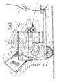
- FIG. 2 The position of the loading flap 2 and the silage block 10 reached after the pivoting movement upwards is shown in FIG. 2.
- the loading flap 2 with the silage block located therein is pivoted upward by approximately 150-160 °.
- the piston sections 81 and 81 'of the telescopic hydraulic cylinder 8 used in the illustrated embodiment are in their extended position brought.
- the previously approximately vertically running frame part 21 'of the loading flap 2 now forms an inclined plane on which the silage block 10 slides through the feed opening 65 against the first tine roller 3.
- This roller 3 or its prongs 31 and scraper webs 32 gradually shred the silage block 10 as a result of the gradual rotation 37 of the roller 3.
- a part of the silage material released from the silage block 10 is conveyed directly from the roller 3 into the discharge area 7, while another part of the silage material is conveyed from the second roller 4 overhead and through the intermediate space 46 to the discharge area 7.
- the shredded and loosened silage falls onto the cross conveyor belt 71, in order to be discharged from there into feed troughs to the left or right of the vehicle.
Description
Die Erfindung betrifft ein verfahrbares Zerkleinerungs- und Austragsgerät für Silageblöcke, mit einem Fahrgestell mit mindestens einer Achse mit Rädern und mit einer mitsamt einem Silageblock von einer Grundstellung in eine Ladestellung hochschwenkbaren Ladeklappe, aus der der Silageblock mittels Schwerkraft gegen eine rotierende Zinkenwalze mit Zinken und/oder Kratzstegen verschiebbar ist, mittels welcher der Block fortschreitend zerkleinerbar und das zerkleinerte Silagegut über Kopf in einen Austragbereich förderbar ist, von wo aus das Silagegut seitlich austragbar ist.The invention relates to a movable crushing and discharge device for silage blocks, with a chassis with at least one axle with wheels and with a complete with a silage block from a basic position to a loading position of the loading flap from which the silage block by gravity against a rotating tine roller with tines and / or scraper bars can be moved, by means of which the block can be shredded progressively and the shredded silage can be conveyed overhead into a discharge area, from where the silage can be discharged laterally.
Ein derartiges Gerät ist aus der DE-OS 33 16 864.4 des Anmelders bekannt und dient dazu, aus einem Fahrsilo ausgeschnittene Silageblöcke aufzunehmen, zu transportieren, zu zerkleinern und schließlich das zerkleinerte Silagegut zu Fütterungszwecken in Futtertröge in einer Stallung auszutragen. Bei dem bekannten Gerät erfolgt die Zerkleinerung des Silageblockes durch die rotierende Zinkenwalze im Zusammenwirken mit von oben her gabelartig zwischen die Zinken der Walze ragenden, am Aufbau des Gerätes starr befestigte Zinken. Bei der Verarbeitung von kurzfaserigem oder körnigem Silagegut, z.B. Mais-Silage, hat sich das Gerät durchaus bewährt. Nachteilig ist jedoch bei dem bekannten Gerät, daß es bei der Verarbeitung von faserigem Silagegut, z.B. Gras-Silage mit Faserlängen von etwas über 10 cm, wie sie bei Grasschnitt üblich sind, zu einem zunehmenden Festsetzen von Silagegut an der Zinkenwalze kommen kann, was im schlimmsten Fall zu einem Blockieren der Walze führt.Such a device is known from DE-OS 33 16 864.4 of the applicant and is used to pick up, transport, shred cut silage blocks from a driving silo and finally to discharge the shredded silage for feeding purposes in feed troughs in a stable. In the known device, the silage block is comminuted by the rotating tine roller in cooperation with tines which protrude from above like a fork between the tines of the roller and are rigidly attached to the structure of the device. When processing short-fiber or granular silage, such as maize silage, the device has proven itself. A disadvantage of the known device, however, is that there is an increasing set in the processing of fibrous silage, for example grass silage with fiber lengths of just over 10 cm, as is customary with grass clippings can come from silage on the tine roller, which in the worst case may result in the roller jamming.
Aus der DE-OS 35 16 861 ist ein Abroll- und Auflockerungsgerät für Rundballen aus faserigen Substanzen bekannt, bei dem ein Rundballen mittels mehrerer gleichdrehsinnig rotierender, mit Zinken versehener Bodenwalzen in Drehung versetzt wird. Eine weitere, schräg oberhalb dieser Bodenwalzen angeordnete Zinkenwalze, dort Zupfwalze genannt, deren Zinken teilweise zwischen die Zinken der schräg darunter liegenden Bodenwalze greifen, rotiert mit höherer Geschwindigkeit, zerkleinert dadurch das bereits durch die Bodenwalzen aufgelockerte Ballengut und befördert es über Kopf aus dem Gerät.From DE-OS 35 16 861 a roll-off and loosening device for round bales made of fibrous substances is known, in which a round bale is rotated by means of several rotating in the same direction rotating, provided with prongs bottom rollers. Another tine roller, arranged diagonally above these floor rollers, called plucking roller there, the tines of which partially grip between the tines of the bottom roller lying diagonally underneath, rotates at a higher speed, thereby shredding the bale material loosened by the bottom rollers and conveying it overhead from the device.
Bei diesem Gerät besteht, wie auch bei dem in der DE-OS 33 16 864.4 beschriebenen, die Gefahr, daß aufgrund der langfaserigen Beschaffenheit des Ballengutes die Zupfwalze zugesetzt wird und blockiert. Es ist dann jedes Mal eine aufwendige Entladung des Gerätes sowie eine Säuberung der Walzen von Hand erforderlich. Das Blockieren der Walze führt leicht zu Schäden an Lagern und Antriebselementen der Walze, was zu häufigeren Reparaturen mit erhöhten Kosten führt.With this device, as with that described in DE-OS 33 16 864.4, there is a risk that the plucking roller will be added and blocked due to the long-fiber nature of the bale material. It is then time-consuming to unload the device and to clean the rollers by hand. Blocking the roller easily leads to damage to bearings and drive elements of the roller, which leads to more frequent repairs with increased costs.
Es stellt sich daher die Aufgabe, ein verfahrbares Zerkleinerungs-und Austragsgerät der eingangs genannten Art zu schaffen, das die genannten Nachteile vermeidet und insbesondere eine problemlose, störungsfreie und zuverlässige Verarbeitung sowohl von kleinfaserigem, körnigem Material wie Mais-Silage, als auch von langfaserigem Material wie Gras-Silage, erlaubt und einfach und kompakt aufgebaut ist.It is therefore the task of creating a movable shredding and discharge device of the type mentioned at the outset which avoids the disadvantages mentioned and in particular problem-free, trouble-free and reliable processing of both small-fiber, granular material such as maize silage and long-fiber material like grass silage, is allowed and is simple and compact.
Die Lösung dieser Aufgabe gelingt erfindungsgemäß durch ein verfahrbares Zerkleinerungs- und Austragsgerät der eingangs genannten Art dadurch, daß oberhalb oder in För derrichtung schräg oberhalb der ersten Zinkenwalze eine zweite, im gleichen Drehsinn rotierende Zinkenwalze angeordnet ist, daß die Zinken der zweiten Zinkenwalze wenigstens teilweise zwischen die Zinken der ersten Zinkenwalze greifen und daß die erste Zinkenwalze mit einem Schritt-Drehantrieb ausgestattet ist.This object is achieved according to the invention by a movable shredding and discharge device of the type mentioned in that above or in För the direction diagonally above the first tine roller, a second tine roller rotating in the same direction is arranged, that the tines of the second tine roller at least partially engage between the tines of the first tine roller and that the first tine roller is equipped with a step rotary drive.
Zwar sind die beiden zuerst genannten Merkmale vorliegender Erfindung einzeln aus dem Stand der Technik bereits bekannt, jedoch ermöglicht es erst ihre Kombination sowie die Ausstattung der ersten Zinkenwalze mit einem Schritt-Drehantrieb die störungsfreie, problemlose und zuverlässige Verarbeitung sowohl von grobkörnigem, wie auch von langfaserigem Silagegut.Although the two first-mentioned features of the present invention are individually known from the prior art, it is only their combination and the fact that the first tine roller is equipped with a step rotary drive that enables trouble-free, problem-free and reliable processing of both coarse-grained and long-fiber Silage.
Mit der Anordnung einer zweiten Zinkenwalze in der oben angegebenen Art wird vorteilhaft erreicht, daß das Silagegut, das von der ersten Zinkenwalze von einem Silageblock gelöst und über Kopf abtransportiert wird, von Zinken der zweiten Zinkenwalze erfaßt wird, sobald es sich in einer unzuträglichen Dicke bzw. Höhe an der ersten Zinkenwalze festgesetzt hat. Da sich die Zinken der beiden gleichsinnig rotierenden Walzen im Überschneidungsbereich ihre Wirkungsbereiche gegeneinander bewegen, wird an der ersten Walze bzw. an deren Zinken festgesetztes Silagegut zuverlässig erfaßt und gelöst. Danach fällt das gelöste Silagegut zum einen Teil in gelokkerter Form wieder auf die erste Walze zurück und zum anderen Teil wird es von der zweiten Walze über Kopf weitertransportiert und fällt dann in den Austragbereich, wohin auch das von der ersten Walze transportierte Silagegut gelangt, das nicht von den Zinken der zweiten Walze erfaßt wurde. Bei der Zerkleinerung von kleinfaserigem, körnigem Silagegut wird letzteres im wesentlichen von der ersten Walze bzw. deren Zinken und den daran angebrachten Kratzblechen oder Stegen transportiert, ohne daß die Zinken der zweiten Walze intensiv zur Wirkung kommen. Dies liegt daran, daß, wie eingangs erwähnt, derartiges Silagegut weniger zum Festsetzen neigt. Um ein solches Festsetzen sicher zu verhindern, ist die erste Zinkenwalze vorteilhaft mit einem Schritt-Drehantrieb ausgestattet, welcher es ermöglicht, daß der zweiten Zinkenwalze immer genügend Zeit verbleibt, etwaig an der ersten Zinkenwalze festsitzendes Silagegut zu lösen und zu lockern, bevor es zu einem Blockieren einer der Walzen kommen kann. Demgegenüber trägt die zweite Walze mit ihren Zinken bei der Verarbeitung von langfaserigem Silagegut sehr wesentlich zur Lockerung und zum Transport des vom Silageblock gelösten Silagegutes und damit zu einer wirkungsvollen und störungsfreien Funktion des Gerätes bei.With the arrangement of a second tine roller of the type specified above, it is advantageously achieved that the silage which is released from a silage block by the first tine roller and is transported overhead is gripped by prongs of the second tine roller as soon as it has an unacceptable thickness or Has fixed height on the first tine roller. Since the tines of the two rollers rotating in the same direction move their effective areas against each other in the overlap region, silage material fixed on the first roller or on its tines is reliably detected and released. Afterwards, the loosened silage partly falls back on the first roller in loosened form and partly it is transported overhead by the second roller and then falls into the discharge area, where the silage transported by the first roller also does not reach was gripped by the tines of the second roller. When crushing small-fiber, granular silage, the latter is essentially transported by the first roller or its tines and the scraper plates or webs attached to them, without the prongs of the second roller having an intensive effect come. This is because, as mentioned at the beginning, such silage is less prone to seizing. In order to reliably prevent such jamming, the first tine roller is advantageously equipped with a step rotary drive, which enables the second tine roller to always have sufficient time to loosen and loosen any silage that may be stuck to the first tine roller before it becomes one Blocking one of the rollers can come up. In contrast, the second roller with its tines makes a significant contribution to loosening and transporting the silage material released from the silage block and thus to an effective and trouble-free function of the device when processing long-fiber silage material.
Eine bevorzugte Ausführungsform des Schritt-Drehantriebes der ersten Zinkenwalze besteht darin, daß diese aus zumindest einer über einen Exzenter hin- und herbewegten Stange besteht, die mit ihrem exzenterabgewandtenA preferred embodiment of the step rotary drive of the first tine roller consists in the fact that it consists of at least one rod which is moved back and forth via an eccentric, the rod facing away from the eccentric
Ende auf einen Hebel wirkt, der mit einseitigem Freilauf mit einer die erste Zinkenwalze tragenden Welle mit Rücklaufsperre gekuppelt ist. Ein solcher Antrieb ist in der Lage, ein sehr großes Drehmoment zu erzeugen. Dieses ist erforderlich, da die zu verarbeitenden Silageblöcke relativ schwer und stark gepreßt sind, so daß das Silagegut einen sehr festen Zusammenhalt hat. Zugleich ist ein derartiger Antrieb sehr robust. Durch die erwähnte Rücklaufsperre wird ein Zurückdrehen der Walze infolge des Gewichtes des auf sie wirkenden Silageblockes verhindert, der unter Umständen während der schrittweisen Rotationsbewegung der ersten Walze von dieser etwas angehoben wird.End acts on a lever which is coupled with one-sided freewheel with a shaft carrying the first tine roller with backstop. Such a drive is able to generate a very large torque. This is necessary because the silage blocks to be processed are relatively heavy and strongly pressed, so that the silage has a very firm cohesion. At the same time, such a drive is very robust. The mentioned backstop prevents the roller from turning back as a result of the weight of the silage block acting on it, which under certain circumstances may be slightly raised by the first roller during the gradual rotational movement of the latter.
Der Durchmesser der zweiten Zinkenwalze beträgt vorzugsweise etwa das 0,4 - 0,7-fache des Durchmessers der ersten Zinkenwalze. Der Durchmesser der ersten Zinkenwalze ist bekanntermaßen durch die Tiefe des Silageblockes festgelegt; er muß zumindest einen dieser Tiefe entsprechenden Durchmesser haben. Der angegebene Durchmesserbereich für die zweite Walze ergibt zum einen eine kompakte Gesamtform des Gerätes und stellt zum anderen zur Vermeidung von Funktionsstörungen sicher, daß die Dimensionen der zweiten Walze deutlich größer sind, als die maximal auftretenden Längen von Fasern des Silagegutes.The diameter of the second tine roller is preferably approximately 0.4-0.7 times the diameter of the first tine roller. The diameter of the first tine roller is known to be determined by the depth of the silage block; it must have at least a diameter corresponding to this depth. The specified diameter range for the second roller results on the one hand in a compact overall shape of the device and on the other hand ensures to avoid malfunctions that the dimensions of the second roller are significantly larger than the maximum lengths of fibers of the silage material that occur.
Für eine gründliche Lösung und Lockerung des Silagegutes, insbesondere von langfaserigem Material, ist es zweckmäßig, daß die Rotation der zweiten Zinkenwalze mit einer Drehzahl erfolgt, die ein Vielfaches der Drehzahl der ersten Zinkenwalze beträgt. Außerdem wird hierdurch die Lösung des Silagegutes von der zweiten Zinkenwalze von den erzeugten Zentrifugalkräften unterstützt. Um zu vermeiden, daß hierbei das Silagegut unkontrolliert herumfliegt, ist ein oberhalb der zweiten Zinkenwalze angeordnetes, diese mit Abstand abdeckendes Silagegut Leitblech vorgesehen. Dieses sorgt dafür, daß das sich von der zweiten Zinkenwalze lösende Silagegut zuverlässig und vollständig in den Austragbereich gelangt. Gleichzeitig verhindert dieses Leitblech, das zugleich eine der Begrenzungen der Zufuhröffnung für den Silageblock bildet, ein zu weites Anheben des Silageblockes durch die erste Zinkenwalze.For a thorough solution and loosening of the silage, in particular of long-fiber material, it is expedient that the rotation of the second tine roller takes place at a speed which is a multiple of the speed of the first tine roller. In addition, the solution of the silage from the second tine roller is supported by the centrifugal forces generated. In order to prevent the silage from flying around in an uncontrolled manner, a silage is arranged above the second tine roller and covers it at a distance Baffle provided. This ensures that the silage material detaching from the second tine roller reaches the discharge area reliably and completely. At the same time, this baffle, which also forms one of the limits of the feed opening for the silage block, prevents the silage block from being raised too far by the first tine roller.
Vorteilhafte Ausführungen der Walzenantriebe ergeben sich aus den Unteransprüchen 7 bis 9.Advantageous designs of the roller drives result from
Zur Anpassung an unterschiedliche Eigenschaften von Silageblöcken ist vorgesehen, daß die Schrittgröße des Schritt-Drehantriebes der ersten Zinkenwalze einstellbar ist.To adapt to different properties of silage blocks, it is provided that the step size of the step rotary drive of the first tine roller is adjustable.
Eine weitere Vereinfachung und zugleich Steigerung der Funktionssicherheit des erfindungsgemäßen Gerätes gegenüber dem Stand der Technik wird dadurch erreicht, daß das Schwenklager der verschwenkbaren Ladeklappe unmittelbar außerhalb des Arbeitsbereiches der Zinken der ersten Zinkenwalze angeordnet ist. Bei dieser Lage des Schwenklagers kann das die erste Zinkenwalze unterseitig umgebende Abdeckblech dicht an der Walze entlanggeführt sein und es wird so sicher verhindert, daß ein Teil des Silageblockes oder Silagegut nach unten zwischen die erste Zinkenwalze und das diese unterseitig umgebende Abdeckblech rutscht. Somit werden Betriebsstörungen ausgeschlossen, wie sie bei der früheren Ausführung infolge eines keilförmig zulaufenden Zwischenraumes zwischen erster Walze und unterseitigem Abdeckblech auftreten konnten.A further simplification and at the same time an increase in the functional reliability of the device according to the invention compared to the prior art is achieved in that the pivot bearing of the pivotable loading flap is arranged directly outside the working area of the tines of the first tine roller. With this position of the pivot bearing, the cover plate surrounding the first tine roller on the underside can be guided closely along the roller and this reliably prevents part of the silage block or silage from sliding down between the first tine roller and the cover plate surrounding it on the underside. This eliminates malfunctions, such as those that could occur in the earlier version due to a wedge-shaped gap between the first roller and the cover plate on the underside.
Eine einfache Konstruktion und eine günstige Verteilung der auftretenden Kräfte für die Verschwenkung der Ladklappe wird dadurch erreicht, daß die verschwenkbare Ladeklappe durch je einen außenseitig angeordneten Hydraulik-Zylinder betätigbar ist, dessen unteres Ende im Bereich der Achse mit dem Fahrgestell verbunden ist und dessen oberes Ende im Abstand vom Schwenklager mit der Ladeklappe verbunden ist.A simple construction and a favorable distribution of the forces occurring for the pivoting of the loading flap is achieved in that the pivoting loading flap is arranged on the outside by one each Hydraulic cylinder can be actuated, the lower end of which is connected to the chassis in the region of the axle and the upper end of which is connected to the loading flap at a distance from the pivot bearing.
Ein bevorzugtes Ausführungsbeispiel der Erfindung wird im folgenden anhand einer Zeichnung näher erläutert. Die Figuren der Zeichnung zeigen im einzelnen:
- Figur 1
- ein Zerkleinerungs- und Austragsgerät für Silageblöcke gemäß der vorliegenden Erfindung, in Seitenansicht, teils in Durchsicht, mit nach unten verschwenkter. Ladeklappe und
Figur 2- das Gerät aus Figur 1 in gleicher Darstellung, mit nach oben verschwenkter Ladeklappe.
- Figure 1
- a shredding and discharge device for silage blocks according to the present invention, in side view, partly in transparency, with pivoted downwards. Tailgate and
- Figure 2
- the device of Figure 1 in the same representation, with the loading flap pivoted upwards.
Wie die Figur 1 zeigt, besteht das dargestellte Ausführungsbeispiel des erfindungsgemäßen Zerkleinerungs- und Austragsgerätes 1 für Silageblöcke 10 im wesentlichen aus einem Fahrgestell 11, einem darauf angeordneten Aufbau 6 und einer daran angelenkten Ladeklappe 2. Das Fahrgestell 11 weist eine Achse 12 mit Rädern 13 auf, die zur Fortbewegung des Gerätes 1 dienen. Das Fahrgestell 11 setzt sich in einer Deichsel 9 fort, die an ihrem freien Ende einen Kupplungskopf 31 zur Verbindung des Gerätes 1 mit einem Traktor 92 trägt.As shown in FIG. 1, the exemplary embodiment of the shredding and discharge device 1 for
Der auf dem Fahrgestell 11 angeordnete Aufbau 6 besteht außenseitig aus einer Stirnwand 61, einer Rückwand 63, Seitenwänden 62 und einer oberseitigen Abdeckung 64. Die oberseitige Abdeckung 64 sowie die Rückwand 63 sind unvollständig ausgeführt, wodurch sich eine sich schräg nach hinten öffnende Zufuhröffnung 65 ergibt. Im Inneren des Aufbaues 6 des Gerätes 1 sind als wesentliche Teile zwei Zinkenwalzen 3 und4 angeordnet. Die erste Zinkenwalze 3 begrenzt die Zufuhröffnung 65 zum Geräteinneren hin, während die zweite Zinkenwalze 4 oberhalb der ersten Walze 3 und etwas zur Frontwand 61 versetzt angeordnet ist. Die erste Zinkenwalze 3 trägt, wie der Name schon sagt, auf ihrem Umfang mehrere Zinken 31, vor die jeweils ein Kratzsteg 32 gesetzt ist. Auch die zweite Zinkenwalze 4 trägt auf ihrem Umfang mehrere Zinken 41. Der Drehsinn der beiden Zinkenwalzen 3 und 4, angedeutet durch die Pfeile 37 und 47, ist gleich und so gerichtet, daß sich jeweils die obere Hälfte der Walzen 3 und 4 zur Frontwand 61 hin bewegt. Die Wirkungsbereiche 31' und 41' der Zinken 31 bzw. 41 der beiden Walzen 3 und 4 überschneiden sich teilweise. Die erste Zinkenwalze 3 ist auf einer Welle 33 in einem Lager 34 gelagert. Dieses Lager 34 ist mit einer Rücklaufsperre ausgestattet, und die Welle 33 bzw. die Walze 3 ist mit einem Hebel 35 derart gekuppelt, daß ein einseitiger Freilauf besteht. Der Hebel 35 ist seinerseits mit einer Stange 56 verbunden, die durch einen Exzenter 54 in eine hin- und hergehende Bewegung versetzbar ist. Durch diese Hin- und Herbewegung der Stange 56 wird die erste Walze 3, wie durch die Anzahl der kurzen Pfeile 37 angedeutet, schrittweise weitergedreht. Das Maß der Bewegung des Hebels 35 und damit die Schrittweite der Drehbewegung der Walze 3 kann durch Versetzen von Anschlägen 57 auf dem freien Ende 56' der Stange 56 unabhängig von deren Bewegungsgröße variiert werden. Je näher die Anschläge 57 an dem Hebel 35 anliegen, desto größer wird die Bewegung des Hebels 35, während bei größerem Abstand der Anschläge 57 vom Hebel 35 das hebelseitige Ende 56' der Stange 56 über einen Teil ihrer Bewegung frei im Hebel 35 gleitet, ohne diesen mitzunehmen. Die zweite Zinkenwalze 4 ist ebenfalls auf einer Welle 43 in einem Lager 44 gelagert. An die zweite Walze 4 ist ein Kettenrad 45 angeflanscht, das über eine Kette 55 in Drehung versetzt wird. Die Kette 55 wird ihrerseits durch ein Kettenrad 53 bewegt, das zusammen mit dem bereits erwähnten Exzenter 54 auf einer gemeinsamen Welle 50 angeordnet ist.The
Der Antrieb der Welle 50 erfolgt unter Zwischenschaltung eines Umlenkgetriebes 52 von einem Zapfwellenanschluß 51 aus, der mit dem Zapfwellenausgang des Traktors 92 verbindbar ist. Letztgenannte Teile bilden zusammen eine Getriebeeinheit 5, die vor der Stirnwand 61 des Aufbaues 6 des Gerätes 1 auf einem Träger 58 angeordnet ist.The drive of the
Der vordere Teil des Inneren des Aufbaues 6 des Gerätes 1 bildet einen Austragbereich 7, durch welchen das zerkleinerte Silagegut herabfällt auf ein quer im Gerät 1 verlaufendes Förderband 71, das in seiner Laufrichtung zweckmäßigerweise umschaltbar ist und einen Austrag des Silagegutes wahlweise nach links oder rechts z. R. in Futtertröge bewirkt.The front part of the interior of the
Die erste Zinkenwalze 3 ist unterseitig von einem Abdeckblech 36 unter Ausbildung eines möglichst kleinen Zwischenraumes umgeben, um ein Eindringen von Teilen des Silageblockes 10 oder von bereits zerkleinertem Silagegut zwischen die Walze 3 und das unterseitige Abdeckblech 36 zu verhindern. Die zweite Zinkenwalze 4 ist oberseitig mit einer als Silagegut-Leitblech ausgebildeten Abdeckung 64 versehen. Diese Abdeckung 64 ist unter Ausbildung eines Zwischenraumes 46 mit Abstand vom Wirkungsbereich 41' der Zinken 41 der Walze 4 angeordnet, um einen ungehinderten Durchtritt von Silagegut zu gewährleisten.The
An der Rückseite bzw. Rückwand 63 des Aufbaues 6 des Gerätes 1 ist die verschwenkbare Ladeklappe 2 mit einem kurzen Schwenkarm 25 in einem Schwenklager 26 angelenkt. Das Schwenklager 26 ist unmittelbar außerhalb des Wirkungsbereiches 31' der ersten Zinkenwalze 3 angeordnet, um eine möglichst günstige Zuführungsrichtung des Silageblockes 10 zu dieser Walze 3 zu erreichen. Die Ladeklappe 2 wird im wesentlichen aus einem Rahmen, bestehend aus einer parallel zur Rückwand 63 des Gerätes 1 verlaufenden Strebe 21' sowie einer in Verlängerung des Schwenkarmes 25 verlaufenden, leicht gebogenen, an ihrem unteren Ende etwa senkrecht zum Untergrund 93 verlaufenden zweiten Strebe 21 gebildet, zwischen denen eine Seitenwand 22, vorzugsweise aus Blech, aufgespannt ist. Nach unten ist die Ladeklappe 2 durch einen in Grundstellung der Ladeklappe unter einem spitzen Winkel zum Untergrund 93 verlaufenden Boden 23 begrenzt, der an seiner Vorderkante 24, die auf dem Untergrund 93 aufliegt, mit einer Hartmetalleiste, vorzugsweise aus Mangan-Hartstahl, versehen ist.On the back or
Der im dargestellten Ausführungsbeispiel innerhalb der Ladeklappe 2 befindliche Silageblock 10 gelangt nach seinem Ausschneiden aus der Silagemasse eines Fahrsilos durch Zurücksetzen des Gerätes 1 dorthin. Zur weiteren Verarbeitung, d. h. zur Zerkleinerung und zum Austragen des zerkleinerten Silagegutes wird die Ladeklappe 2 mitsamt dem Silageblock 10 in Richtung des Pfeiles 28 nach oben verschwenkt. Diese Verschwenkung wird durch einen Hydraulikzylinder 8 bewirkt, der mit seinem unteren Ende 83 an einem Anlenkpunkt 84 in der Nähe der Achse 12 am Fahrgestell 11 angelenkt ist, und dessen oberes Ende 82 am Kolben 81 an einem Anlenkpunkt 27 am Rahmenteil 21' der Ladeklappe 2 angelenkt ist. Zur Erzeugung einer ausreichenden Schwenkkraft und für eine gleichmäßige Verteilung der auftretenden Kräfte ist zweckmäßig links und rechts am Gerät 1 je ein Hydraulikzylinder 8 angeordnet.The
Die nach der Schwenkbewegung nach oben erreichte Stellung der Ladeklappe 2 und des Silageblockes 10 zeigt die Figur 2. Hier ist die Ladeklappe 2 mit dem darin befindlichen Silageblock um etwa 150 - 160° nach oben verschwenkt. Hierzu sind die Kolbenteilstücke 81 und 81' des im dargestellten Ausführungsbeispiel verwendeten Teleskop-Hydraulikzylinders 8 in ihre Ausfahrstellung gebracht. Das vorher etwa vertikal verlaufende Rahmenteil 21' der Ladeklappe 2 bildet nun eine schiefe Ebene, auf welcher der Silageblock 10 durch die Zufuhröffnung 65 gegen die erste Zinkenwalze 3 rutscht. Diese Walze 3 bzw. deren Zinken 31 und Kratzstege 32 zerkleinern den Silageblock 10 infolge der schrittweisen Drehung 37 der Walze 3 nach und nach. Ein Teil des vom Silageblock 10 gelösten Silagegutes wird unmittelbar von der Walze 3 in den Austragbereich 7 gefördert, während ein anderer Teil des Silagegutes von der zweiten Walze 4 über Kopf und durch den Zwischenraum 46 zum Austragbereich 7 gefördert wird. Im Austragbereich 7 fällt das zerkleinerte und gelockerte Silagegut auf das Querförderband 71, um von dort in links oder rechts vom Fahrzeug vorhandene Futtertröge ausgetragen zu werden.The position of the
Claims (11)
- A movable crushing and discharge apparatus (1) for silage blocks (10) with a chassis (11), with at least one axle (12), with wheels (13), and with a loading flap (2), which together with a silage block is able to be swung up from a base position into a loading position, from which flap the silage block is able to be moved by means of gravity towards a rotating toothed roller (3) with teeth (31) and/or scraping cross-pieces (32), by means of which the block is able to be progressively crushed and the crushed silage material is able to be conveyed overhead into a discharge region (7), from which the silage material is able to be discharged to the side,
characterized in that
- above or in the conveying direction (37) obliquely above the first toothed roller (3) , a second toothed roller (4) is arranged rotating in the same direction of rotation (47),- the teeth (41) of the second toothed roller (4) engage at least partially between the teeth (31) of the first toothed roller (3) and- the first toothed roller (3) is equipped with a stepping rotary drive (34, 35, 54, 56). - An apparatus according to Claim 1, characterized in that the stepping rotary drive of the first toothed roller (3) consists of at least one rod (56) which is moved to and fro via an eccentric (54), which rod, with its end (56') facing away from the eccentric, acts upon a lever (35), which is coupled with a free-runniing arrangement (45), on one side, with a shaft (33) with back stop, carrying the first toothed roller (3).
- An apparatus according to one of Claims 1 to 2, characterized in that the diameter of the second toothed roller (4) is approximately 0.4 - 0.7 times the diameter of the first toothed roller (3).
- An apparatus according to at least one of Claims 1 to 3, characterized in that the rotation of the second toothed roller (4) takes place with a rotational speed which is a multiple of the rotational speed of the first toothed roller (3).
- An apparatus according to at least one of Claims 1 to 4, characterized in that above the second toothed roller (4), a silage baffle (64) is arranged, which covers the latter at a distance.
- An apparatus according to at least one of Claims 1 to 5, characterized in that the second toothed roller (4) has a chain drive (45, 53, 55).
- An apparatus according to at least one of Claims 1 to 6, characterized in that the eccentric (54) for the stepping rotary drive of the first toothed roller (3) and the chain wheel (53) for the chain drive of the second toothed roller (4) are arranged on a common shaft (50).
- An apparatus according to at least one of Claims 1 to 7, characterized in that the common shaft (50) is able to be driven from a drawing vehicle (92) with the interposition of a gear (5).
- An apparatus according to at least one of Claims 1 to 8, characterized in that the extent of stepping (37) of the stepping rotary drive (34, 35, 54, 56) of the first toothed roller (3) is able to be adjusted.
- An apparatus according to one of Claims 1 to 9, characterized in that the swivel bearing (26) of the sluable loading flap (2) is arranged immediately outside the range of action (31') of the teeth (31) of the first toothed roller (3).
- An apparatus according to at least one of Claims 1 to 10, characterized in that the sluable loading flap (2) is able to be actuated by a hydraulic cylinder (8) arranged in each case on the outside, the lower end (83) of which is connected with the chassis (11) in the region of the axle (12), and the upper end (82) of which is connected with the loading flap at a distance from the swivel bearing (26).
Applications Claiming Priority (2)
| Application Number | Priority Date | Filing Date | Title |
|---|---|---|---|
| DE3540862 | 1985-11-18 | ||
| DE19853540862 DE3540862A1 (en) | 1985-11-18 | 1985-11-18 | MOVABLE SHREDDING AND DISCHARGE DEVICE FOR SILAGE BLOCKS |
Publications (2)
| Publication Number | Publication Date |
|---|---|
| EP0223004A1 EP0223004A1 (en) | 1987-05-27 |
| EP0223004B1 true EP0223004B1 (en) | 1991-02-27 |
Family
ID=6286291
Family Applications (1)
| Application Number | Title | Priority Date | Filing Date |
|---|---|---|---|
| EP86112613A Expired - Lifetime EP0223004B1 (en) | 1985-11-18 | 1986-09-12 | Mobile bale shredder and discharger |
Country Status (2)
| Country | Link |
|---|---|
| EP (1) | EP0223004B1 (en) |
| DE (2) | DE3540862A1 (en) |
Families Citing this family (12)
| Publication number | Priority date | Publication date | Assignee | Title |
|---|---|---|---|---|
| DE3938968A1 (en) * | 1989-11-24 | 1991-05-29 | Lengerich Maschf | Tractor-mounted implement for silage removal - has pre-conveyors with rotary loosening tools |
| GB2255956B (en) * | 1990-03-28 | 1993-04-07 | Leslie Stephen Harry Salmon | Processing apparatus for baled materials |
| GB2243593B (en) * | 1990-03-28 | 1992-12-09 | Leslie Stephan Harry Salmon | Processing apparatus for baled materials |
| DE4027527A1 (en) * | 1990-08-31 | 1992-03-05 | Strautmann & Soehne | Implement for taking up and cutting bales of straw or fodder - consists of swinging platform which loads bales into cutters from which they are conveyed to roller cutters |
| DE9213867U1 (en) * | 1992-10-14 | 1992-12-10 | Ingenieurbetrieb Agritechnik Gmbh, O-8355 Neustadt, De | |
| DE102004006316A1 (en) | 2004-02-09 | 2005-08-25 | Michael Prof. Dr. Kratzer | Device for measuring the aggregation and / or the coagulation and / or the viscosity of the blood |
| US7204200B2 (en) * | 2004-12-08 | 2007-04-17 | Rovibec Inc. | Utility car for maintenance of livestock |
| EP2127516B1 (en) | 2008-05-27 | 2012-01-25 | Bernard van Lengerich Maschinenfabrik GmbH & Co. KG | Device for removing silage from a silo |
| US10681870B2 (en) * | 2016-05-16 | 2020-06-16 | Tanner Matheson | Hay bale feeder |
| CN107597309B (en) * | 2017-11-14 | 2019-05-24 | 新沂市创科石英有限公司 | It is a kind of to produce anti-blocking feed opening using ball mill grinding |
| CN109005961B (en) * | 2018-08-22 | 2023-07-18 | 甘肃农业大学 | Silage silk kneading machine |
| US11653677B2 (en) | 2020-01-30 | 2023-05-23 | Deere & Company | Extreme crop processing after ensiling |
Family Cites Families (6)
| Publication number | Priority date | Publication date | Assignee | Title |
|---|---|---|---|---|
| GB1107551A (en) * | 1964-03-03 | 1968-03-27 | Massey Ferguson Perkins Ltd | Improvements in combine harvester rear beaters |
| NL6600481A (en) * | 1966-01-14 | 1967-07-17 | ||
| US3863850A (en) * | 1974-02-25 | 1975-02-04 | Percy F Freeman | Bale shredder and discharger |
| US4170426A (en) * | 1977-12-27 | 1979-10-09 | Hesston Corporation | Bale disintegrator and method |
| DE3316864A1 (en) * | 1983-05-07 | 1984-11-08 | Hoopman Onderzoek en Ontwikkeling B.V., Aalten | Process for comminuting and discharging silage blocks and mobile appliance for carrying out the process |
| DE3516861A1 (en) * | 1985-05-10 | 1985-10-31 | Anton 4478 Geeste Knoll | Rolling and opening appliance for round bales of straw, hay, grass silage and other fibrous substances |
-
1985
- 1985-11-18 DE DE19853540862 patent/DE3540862A1/en active Granted
-
1986
- 1986-09-12 EP EP86112613A patent/EP0223004B1/en not_active Expired - Lifetime
- 1986-09-12 DE DE8686112613T patent/DE3677707D1/en not_active Expired - Fee Related
Also Published As
| Publication number | Publication date |
|---|---|
| DE3540862A1 (en) | 1987-05-21 |
| DE3540862C2 (en) | 1990-01-18 |
| EP0223004A1 (en) | 1987-05-27 |
| DE3677707D1 (en) | 1991-04-04 |
Similar Documents
| Publication | Publication Date | Title |
|---|---|---|
| EP0223004B1 (en) | Mobile bale shredder and discharger | |
| DE2118914A1 (en) | Mower consisting of at least one pair of interacting mowing rotors and a downstream pair of squeezing rollers consisting of a crop processing machine | |
| EP0787425A1 (en) | Chopper and conveying device | |
| EP0574942B1 (en) | Machine for gathering, transporting, cutting and distributing fodder or mulch | |
| EP1417879A1 (en) | Pick-up for agricultural produce | |
| DE1757270B1 (en) | Work device for the onward conveyance of agricultural material | |
| DE19603370C2 (en) | Harvester | |
| EP0176057A2 (en) | Chopper for organic material | |
| EP0086478B1 (en) | Device for disintegrating forage blocks cut from a silo | |
| DE19750954A1 (en) | Pickup device for agricultural machine | |
| AT413314B (en) | Straw | |
| DE3614234C2 (en) | ||
| DE3337390C1 (en) | Device for transporting and comminuting round bales | |
| DE102010063049A1 (en) | Feeding unit for conveying and pressing device, comprises feeding space for pressed material, where base of feeding space is bent in form of cylindrical jacket section | |
| EP0014854A1 (en) | Collecting device for a forage harvester | |
| DE3124187C2 (en) | Mobile device with a device for picking up clippings for the treatment of cut, swath-shaped plant material | |
| DE4113630C2 (en) | Processing machine for stalks | |
| DE2443914A1 (en) | DEVICE FOR PICKING UP AND TRANSFERRING BULK GOODS, IN PARTICULAR HALM AND LEAF FRUITS | |
| DE4121328C2 (en) | Transport and discharge device for a feed block | |
| DE4113631C2 (en) | Processing machine for stalks | |
| DE2500787A1 (en) | CHICKEN MANURE SPREADER | |
| DE60101644T2 (en) | Agricultural machine for distributing products | |
| DE3516861A1 (en) | Rolling and opening appliance for round bales of straw, hay, grass silage and other fibrous substances | |
| DE3507517A1 (en) | Device for mulching various chopped materials | |
| DE3609631A1 (en) | Appliance for the pressing and cutting of cylindrical bales of stalk-like material |
Legal Events
| Date | Code | Title | Description |
|---|---|---|---|
| PUAI | Public reference made under article 153(3) epc to a published international application that has entered the european phase |
Free format text: ORIGINAL CODE: 0009012 |
|
| AK | Designated contracting states |
Kind code of ref document: A1 Designated state(s): BE DE FR GB IT NL |
|
| 17P | Request for examination filed |
Effective date: 19871123 |
|
| 17Q | First examination report despatched |
Effective date: 19890904 |
|
| GRAA | (expected) grant |
Free format text: ORIGINAL CODE: 0009210 |
|
| AK | Designated contracting states |
Kind code of ref document: B1 Designated state(s): BE DE FR GB IT NL |
|
| ITF | It: translation for a ep patent filed |
Owner name: DE DOMINICIS & MAYER S.R.L. |
|
| GBT | Gb: translation of ep patent filed (gb section 77(6)(a)/1977) | ||
| REF | Corresponds to: |
Ref document number: 3677707 Country of ref document: DE Date of ref document: 19910404 |
|
| ET | Fr: translation filed | ||
| PGFP | Annual fee paid to national office [announced via postgrant information from national office to epo] |
Ref country code: BE Payment date: 19910801 Year of fee payment: 6 |
|
| PGFP | Annual fee paid to national office [announced via postgrant information from national office to epo] |
Ref country code: GB Payment date: 19910805 Year of fee payment: 6 |
|
| PGFP | Annual fee paid to national office [announced via postgrant information from national office to epo] |
Ref country code: FR Payment date: 19910927 Year of fee payment: 6 |
|
| PGFP | Annual fee paid to national office [announced via postgrant information from national office to epo] |
Ref country code: NL Payment date: 19910930 Year of fee payment: 6 |
|
| PGFP | Annual fee paid to national office [announced via postgrant information from national office to epo] |
Ref country code: DE Payment date: 19911126 Year of fee payment: 6 |
|
| PLBE | No opposition filed within time limit |
Free format text: ORIGINAL CODE: 0009261 |
|
| STAA | Information on the status of an ep patent application or granted ep patent |
Free format text: STATUS: NO OPPOSITION FILED WITHIN TIME LIMIT |
|
| 26N | No opposition filed | ||
| PG25 | Lapsed in a contracting state [announced via postgrant information from national office to epo] |
Ref country code: GB Effective date: 19920912 |
|
| PG25 | Lapsed in a contracting state [announced via postgrant information from national office to epo] |
Ref country code: BE Effective date: 19920930 |
|
| BERE | Be: lapsed |
Owner name: DE DISSEL BEHEER B.V. Effective date: 19920930 |
|
| PG25 | Lapsed in a contracting state [announced via postgrant information from national office to epo] |
Ref country code: NL Effective date: 19930401 |
|
| GBPC | Gb: european patent ceased through non-payment of renewal fee |
Effective date: 19920912 |
|
| NLV4 | Nl: lapsed or anulled due to non-payment of the annual fee | ||
| PG25 | Lapsed in a contracting state [announced via postgrant information from national office to epo] |
Ref country code: FR Effective date: 19930528 |
|
| PG25 | Lapsed in a contracting state [announced via postgrant information from national office to epo] |
Ref country code: DE Effective date: 19930602 |
|
| REG | Reference to a national code |
Ref country code: FR Ref legal event code: ST |
|
| PG25 | Lapsed in a contracting state [announced via postgrant information from national office to epo] |
Ref country code: IT Free format text: LAPSE BECAUSE OF NON-PAYMENT OF DUE FEES;WARNING: LAPSES OF ITALIAN PATENTS WITH EFFECTIVE DATE BEFORE 2007 MAY HAVE OCCURRED AT ANY TIME BEFORE 2007. THE CORRECT EFFECTIVE DATE MAY BE DIFFERENT FROM THE ONE RECORDED. Effective date: 20050912 |