EP0485789B1 - Vorrichtung zur Erfassung und optischen Anzeige des Einschlagwinkels eines gelenkten Rades eines Kraftfahrzeuges - Google Patents
Vorrichtung zur Erfassung und optischen Anzeige des Einschlagwinkels eines gelenkten Rades eines Kraftfahrzeuges Download PDFInfo
- Publication number
- EP0485789B1 EP0485789B1 EP91118285A EP91118285A EP0485789B1 EP 0485789 B1 EP0485789 B1 EP 0485789B1 EP 91118285 A EP91118285 A EP 91118285A EP 91118285 A EP91118285 A EP 91118285A EP 0485789 B1 EP0485789 B1 EP 0485789B1
- Authority
- EP
- European Patent Office
- Prior art keywords
- angle
- hall effect
- effect devices
- wheel
- alpha
- Prior art date
- Legal status (The legal status is an assumption and is not a legal conclusion. Google has not performed a legal analysis and makes no representation as to the accuracy of the status listed.)
- Expired - Lifetime
Links
Images

Classifications
-
- B—PERFORMING OPERATIONS; TRANSPORTING
- B62—LAND VEHICLES FOR TRAVELLING OTHERWISE THAN ON RAILS
- B62D—MOTOR VEHICLES; TRAILERS
- B62D15/00—Steering not otherwise provided for
- B62D15/02—Steering position indicators ; Steering position determination; Steering aids
-
- G—PHYSICS
- G01—MEASURING; TESTING
- G01D—MEASURING NOT SPECIALLY ADAPTED FOR A SPECIFIC VARIABLE; ARRANGEMENTS FOR MEASURING TWO OR MORE VARIABLES NOT COVERED IN A SINGLE OTHER SUBCLASS; TARIFF METERING APPARATUS; MEASURING OR TESTING NOT OTHERWISE PROVIDED FOR
- G01D5/00—Mechanical means for transferring the output of a sensing member; Means for converting the output of a sensing member to another variable where the form or nature of the sensing member does not constrain the means for converting; Transducers not specially adapted for a specific variable
- G01D5/12—Mechanical means for transferring the output of a sensing member; Means for converting the output of a sensing member to another variable where the form or nature of the sensing member does not constrain the means for converting; Transducers not specially adapted for a specific variable using electric or magnetic means
- G01D5/14—Mechanical means for transferring the output of a sensing member; Means for converting the output of a sensing member to another variable where the form or nature of the sensing member does not constrain the means for converting; Transducers not specially adapted for a specific variable using electric or magnetic means influencing the magnitude of a current or voltage
- G01D5/142—Mechanical means for transferring the output of a sensing member; Means for converting the output of a sensing member to another variable where the form or nature of the sensing member does not constrain the means for converting; Transducers not specially adapted for a specific variable using electric or magnetic means influencing the magnitude of a current or voltage using Hall-effect devices
- G01D5/145—Mechanical means for transferring the output of a sensing member; Means for converting the output of a sensing member to another variable where the form or nature of the sensing member does not constrain the means for converting; Transducers not specially adapted for a specific variable using electric or magnetic means influencing the magnitude of a current or voltage using Hall-effect devices influenced by the relative movement between the Hall device and magnetic fields
Definitions
- the invention relates to a device for detecting and optically displaying the steering angle of a steered wheel of a motor vehicle according to the preamble of claim 1.
- EP-OS 232 072 shows a device for a steered wheel, which determines without contact whether the current turning angle exceeds a preset turning angle. With this signal, the drive motors are controlled so that the steering movement is supported. However, this signal, which characterizes the steering angle, is not passed on to the driver, and it can only be recognized whether the steering angle is above or below the preset steering angle. In addition, the optical switching means used as angle encoders are sensitive to contamination.
- DE-OS 38 30 845 proposes to provide an instrument for displaying a steering angle of a steered wheel with an optical signal transmitter for displaying the forward driving direction and, if appropriate, a further optical signal transmitter for displaying the reverse driving direction.
- the turning angle is to be displayed via a moving light bar, the drive of which, however, makes no reference to the present publication.
- a device for displaying the steering angle of a steering wheel of a motor vehicle which uses a scale with optical display elements.
- the display elements corresponding to the steering angle light up for display. At least one display element is provided for each direction of travel, so that overall a large number of display elements, associated with corresponding costs, is required.
- EP 0 381 963 A1 shows a device for determining the steering wheel rotation angle of a motor vehicle, in which a rotation angle sensor arranged on the steering wheel is designed as a contactless rotation angle change sensor.
- This rotation angle change sensor consists of a cylindrical wound magnetic film, which is magnetized alternately in the circumferential direction with regard to its magnetic polarity and two corresponding magnetic field sensors, which are arranged offset, so that they emit two phase-shifted sinusoidal output signals.
- the object of the invention is based on DE-OS 38 30 845 to provide a device for detecting and displaying the steering angle of a steered wheel and the direction of travel of a motor vehicle, which has no moving parts and is both robust and insensitive to contamination, the effort on components should be kept low.
- the advantages achieved with the invention are above all the robustness, the insensitivity to dirt, installation tolerances or the like and low manufacturing costs.
- the robustness results from the use of non-moving parts and in particular from the use of Hall sensors in connection with a ring magnet section for detecting the steering angle.
- this arrangement ensures insensitivity to dirt and installation tolerances.
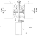
- the wheel 1 shows a steered wheel 1 of a vehicle, in particular a 3-wheel forklift.
- the wheel 1 is connected to a body 4 of the forklift truck via a steering axle 2 and two ball bearings 3 and has a maximum steering angle of +/- 90 °.
- a switching device 5 used to detect the steering angle of the steered wheel 1 consists of an annular upper carrier plate 6, which is attached to the body, and a lower carrier plate 7, which is rigidly connected to the steering axle 2.
- the upper support plate 6 and the lower support plate 7 are spaced parallel to each other and perpendicular to the steering axis 2.
- Hall sensors 8 are attached in a semicircle to the underside of the upper support plate 6.
- a ring magnet section 9 is arranged on the side of the lower support plate 7 facing the upper support plate 6 such that the Hall sensors 8 are in its area of operation and can be switched by it.
- Other rotationally symmetrical arrangements are. also possible, e.g. B. two concentric cylinders.
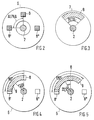
- a first angle ALPHA between two adjacent Hall sensors 8 in the selected example is 90 °, so that 3 Hall sensors 8, 8 'and 8''are required.
- the Hall sensors 8 are to be arranged on a semicircle in such a way that one Hall sensor 8 is seated on the end points of the semicircle and the remaining Hall sensors 8 are arranged at equal angular intervals ALPHA in between.
- the circular diameter describing the ring magnet section 9 is as large as the circular diameter describing the arrangement of the Hall sensors 8.
- it comprises a second angle BETA of 90 ° corresponding to 1 times the first angle ALPHA between two adjacent Hall sensors 8.
- the ring magnet section 9 comprises a second angle BETA 'of 135 °, which corresponds to 1.5 times the first angle ALPHA between two adjacent Hall sensors 8. With an increasing steering angle, from a steering angle of 22.5 ° Hall sender 8 'switched. The Hall sender 8 remains switched through until it is released by the ring magnet section 9 from a turning angle of 67.5 °.
- Version 1 Hall sender ⁇ steering lock 0 - 45 ° 45 - 90 ° 8th 1 0 8th' 0 1
- Version 2 Hall sender ⁇ steering lock 0-22.5 ° 22.5 - 67.5 ° 67.5 - 90 ° 8th 1 1 0 8th' 0 1 1
- the direction information is output to the driver via a display instrument 10 (FIG. 6).
- a scale 11 of the display instrument 10 is included Luminous bodies, in the example shown, 4 light-emitting diodes (LEDs) 12, which are arranged at a third angle GAMMA spaced from each other in a circle.
- the LEDs 12 are advantageously designed as triangles, the tips of which each point towards the edge of the display instrument 10.
- the display instrument 10 is installed in the vehicle so that the LED 12 points in the forward direction V.
- the assignment of the Hall sensors 8 to the LEDs 12 is advantageously selected such that the LEDs 12 represent the arrangement of the Hall sensors 8.
- the Hall sensor 8, which is switched through during forward travel, will thus light up the LED 12 pointing in the forward travel direction.
- the direction signal 13 goes "forward” and the AND gates 14 block the signals from the Hall sensors 8.
- an inverter 15 connected to the direction signal 13 is now switched through, the signal AND gate 16 of which controls and thus the the AND gate 16 also pending signals from Hall 8.
- the outputs of the AND gates 16 are connected to the LEDs 12 via driver stages (not shown here) in such a way that the assignment of Hall sensors 8 to the LEDs 12 is rotated by 180 ° with respect to the assignment when driving forward. If, for example, Hall sensor 8 (forward) is switched, LED 12 '' '(backward) lights up. The LED 12 '(turn left) lights up in an analogous manner when the Hall sensor 8' '(turn right) is switched on.
- the OR's 17 ' are connected upstream of the LEDs 12' and 12 '', which can be controlled both in the forward and in the reverse run.
- the inputs of the OR gates 17 are connected to the outputs of the corresponding AND gates 14 and 16.
- the driver is shown the impending direction of movement of the steered wheel.
- this corresponds to the movement of the rear of the vehicle because the steered wheel is behind the axis of rotation of the vehicle.
- the movement of the fork will be opposite. Therefore, in a further embodiment, not shown, the LEDs 12 'and LED 12''are interchanged in order to indicate the movement of the fork.
- the switching device 5 can alternatively according to other non-contact principles, such. B. the inductive or capacitive principle.
- the LEDs 12 can be replaced by other optical display elements without impairing the function of the device according to the invention.
Landscapes
- Engineering & Computer Science (AREA)
- Chemical & Material Sciences (AREA)
- Combustion & Propulsion (AREA)
- Transportation (AREA)
- Mechanical Engineering (AREA)
- Physics & Mathematics (AREA)
- General Physics & Mathematics (AREA)
- Forklifts And Lifting Vehicles (AREA)
- Lighting Device Outwards From Vehicle And Optical Signal (AREA)
Applications Claiming Priority (2)
| Application Number | Priority Date | Filing Date | Title |
|---|---|---|---|
| DE4035794A DE4035794A1 (de) | 1990-11-10 | 1990-11-10 | Vorrichtung zur erfassung und optischen anzeige des einschlagwinkels eines gelenkten rades eines kraftfahrzeuges |
| DE4035794 | 1990-11-10 |
Publications (3)
| Publication Number | Publication Date |
|---|---|
| EP0485789A2 EP0485789A2 (de) | 1992-05-20 |
| EP0485789A3 EP0485789A3 (en) | 1992-09-02 |
| EP0485789B1 true EP0485789B1 (de) | 1994-12-28 |
Family
ID=6418001
Family Applications (1)
| Application Number | Title | Priority Date | Filing Date |
|---|---|---|---|
| EP91118285A Expired - Lifetime EP0485789B1 (de) | 1990-11-10 | 1991-10-26 | Vorrichtung zur Erfassung und optischen Anzeige des Einschlagwinkels eines gelenkten Rades eines Kraftfahrzeuges |
Country Status (2)
| Country | Link |
|---|---|
| EP (1) | EP0485789B1 (enExample) |
| DE (2) | DE4035794A1 (enExample) |
Families Citing this family (5)
| Publication number | Priority date | Publication date | Assignee | Title |
|---|---|---|---|---|
| DE4416790C1 (de) * | 1993-09-20 | 1995-06-01 | Kroll Fahrzeugbau Umwelt | Verfahren und Einrichtung zum Führen eines Straßenfahrzeuges |
| DE4332287C1 (de) * | 1993-09-20 | 1994-11-03 | Kroll Fahrzeugbau Umwelt | Verfahren und Einrichtung zum Führen eines Straßenfahrzeuges, vorzugsweise in engen Verkehrsflächen |
| NZ299747A (en) * | 1996-11-13 | 1999-05-28 | A J & J P Smith Ltd | Indication of wheel angles for remote steering operation |
| DE19716866C1 (de) * | 1997-04-22 | 1998-07-02 | Dieter Willi Reimer | Anzeigevorrichtung für die Stellung von lenkbaren Rädern |
| SE520459C2 (sv) * | 1998-09-11 | 2003-07-15 | Inmotion Technologies Ab | Servostyrsystem med positionskalibrerande anordning för elektriska fordon |
Family Cites Families (7)
| Publication number | Priority date | Publication date | Assignee | Title |
|---|---|---|---|---|
| CH605236A5 (enExample) * | 1976-12-31 | 1978-09-29 | Parsot Jon | |
| DE3214794C2 (de) * | 1982-04-21 | 1984-06-07 | Dr. Johannes Heidenhain Gmbh, 8225 Traunreut | Magnetische Längen- oder Winkelmeßeinrichtung |
| DE3345804A1 (de) * | 1983-12-17 | 1985-06-27 | Vdo Adolf Schindling Ag, 6000 Frankfurt | Geraet zur beruehrungslosen elektronischen winkelmessung |
| GB8601841D0 (en) * | 1986-01-25 | 1986-02-26 | Yale Materials Handling Ltd | Vehicles |
| DE3732958A1 (de) * | 1987-09-30 | 1989-04-20 | Bosch Gmbh Robert | Drehstellungsgeber zur sensierung der drehstellung eines rotierenden koerpers |
| DE3830845C2 (de) * | 1988-09-10 | 1996-02-29 | Linde Ag | Instrument für ein Kraftfahrzeug zur Anzeige des Lenkeinschlags der gelenkten Räder |
| DE3903359A1 (de) * | 1989-02-05 | 1990-08-09 | Bayerische Motoren Werke Ag | Einrichtung zur bestimmung des lenkraddrehwinkels eines kraftfahrzeuges |
-
1990
- 1990-11-10 DE DE4035794A patent/DE4035794A1/de active Granted
-
1991
- 1991-10-26 EP EP91118285A patent/EP0485789B1/de not_active Expired - Lifetime
- 1991-10-26 DE DE59104066T patent/DE59104066D1/de not_active Expired - Fee Related
Also Published As
| Publication number | Publication date |
|---|---|
| EP0485789A3 (en) | 1992-09-02 |
| DE59104066D1 (de) | 1995-02-09 |
| EP0485789A2 (de) | 1992-05-20 |
| DE4035794C2 (enExample) | 1993-02-11 |
| DE4035794A1 (de) | 1992-05-14 |
Similar Documents
| Publication | Publication Date | Title |
|---|---|---|
| EP0699151B1 (de) | Sensor zur erfassung des lenkwinkels | |
| DE3146740C2 (de) | Anordnung zum Rückstellen einer Fahrtrichtungsanzeige eines Fahrzeugs | |
| WO1993012403A1 (de) | Drehzahlsensor, insbesondere zahnradsensor | |
| EP2046608B1 (de) | Kontaktloser schalter | |
| DE3500409C2 (enExample) | ||
| DE10103853B4 (de) | Verfahren zur Ansteuerung einer Warnlampe bei einem Antiblockiersystem für Strassenfahrzeuge | |
| EP0485789B1 (de) | Vorrichtung zur Erfassung und optischen Anzeige des Einschlagwinkels eines gelenkten Rades eines Kraftfahrzeuges | |
| DE19744722B4 (de) | Anordnung zum Erfassen des Lenkwinkels in Kraftfahrzeugen | |
| DE2217011A1 (de) | Vorrichtung zur druckueberwachung, insbesondere zur ueberwachung des druckes von kraftfahrzeugreifen | |
| EP0886817A2 (de) | Rastschaltwerk | |
| DE2460918C2 (de) | Einrichtung zum Ausschalten eines Fahrtrichtungsanzeigers bei einem Kraftfahrzeug nach einer Kurvenfahrt | |
| EP4136014B1 (de) | System umfassend einen routenzug und mindestens eine stationäre übernahmestation | |
| EP2065255B1 (de) | Lenkradhupe | |
| DE102009006307A1 (de) | Lichtquelleneinheit | |
| DE202004010944U1 (de) | Flurförderzeug mit mindestens einer Arbeitsbeleuchtungsvorrichtung | |
| DE2413066C3 (de) | Fahrtrichtungsanzeige-Steuerschaltung | |
| DE2435494C2 (de) | Lenkvorrichtung für fahrerlose Flurförderzeuge | |
| DE102008037080A1 (de) | Bedieneinrichtung zum Erzeugen von elektrischen Steuersignalen | |
| DE4025950A1 (de) | Hinterradlenkeinrichtung eines allradgelenkten kraftfahrzeugs | |
| DE10328753A1 (de) | Vorrichtung zum Messen des Lenkstangenweges einer Kraftfahrzeuglenkung | |
| WO2021089256A1 (de) | Lenkstockmodul mit einer bedienvorrichtung zum einstellen eines betriebsparameters eines kraftfahrzeugs und kraftfahrzeug mit einem solchen lenkstockmodul | |
| DE3830845C2 (de) | Instrument für ein Kraftfahrzeug zur Anzeige des Lenkeinschlags der gelenkten Räder | |
| EP1492689A1 (de) | Vorrichtung zur detektion der position eines fahrzeugs bei einer fahrzeugbehandlungsanlage | |
| DE102025113015A1 (de) | Lenkvorrichtung | |
| DE3118001A1 (de) | Fahrtrichtungs-anzeigeeinrichtung fuer kraftfahrzeuge mit elektronischer rueckstelleinrichtung |
Legal Events
| Date | Code | Title | Description |
|---|---|---|---|
| PUAI | Public reference made under article 153(3) epc to a published international application that has entered the european phase |
Free format text: ORIGINAL CODE: 0009012 |
|
| AK | Designated contracting states |
Kind code of ref document: A2 Designated state(s): DE FR GB IT |
|
| PUAL | Search report despatched |
Free format text: ORIGINAL CODE: 0009013 |
|
| AK | Designated contracting states |
Kind code of ref document: A3 Designated state(s): DE FR GB IT |
|
| 17P | Request for examination filed |
Effective date: 19920923 |
|
| 17Q | First examination report despatched |
Effective date: 19930830 |
|
| ITF | It: translation for a ep patent filed | ||
| GRAA | (expected) grant |
Free format text: ORIGINAL CODE: 0009210 |
|
| AK | Designated contracting states |
Kind code of ref document: B1 Designated state(s): DE FR GB IT |
|
| REF | Corresponds to: |
Ref document number: 59104066 Country of ref document: DE Date of ref document: 19950209 |
|
| GBT | Gb: translation of ep patent filed (gb section 77(6)(a)/1977) |
Effective date: 19950112 |
|
| ET | Fr: translation filed | ||
| PLBE | No opposition filed within time limit |
Free format text: ORIGINAL CODE: 0009261 |
|
| STAA | Information on the status of an ep patent application or granted ep patent |
Free format text: STATUS: NO OPPOSITION FILED WITHIN TIME LIMIT |
|
| 26N | No opposition filed | ||
| PGFP | Annual fee paid to national office [announced via postgrant information from national office to epo] |
Ref country code: GB Payment date: 19961017 Year of fee payment: 6 |
|
| PGFP | Annual fee paid to national office [announced via postgrant information from national office to epo] |
Ref country code: DE Payment date: 19961022 Year of fee payment: 6 |
|
| PGFP | Annual fee paid to national office [announced via postgrant information from national office to epo] |
Ref country code: FR Payment date: 19961028 Year of fee payment: 6 |
|
| PG25 | Lapsed in a contracting state [announced via postgrant information from national office to epo] |
Ref country code: GB Free format text: LAPSE BECAUSE OF NON-PAYMENT OF DUE FEES Effective date: 19971026 |
|
| PG25 | Lapsed in a contracting state [announced via postgrant information from national office to epo] |
Ref country code: FR Free format text: THE PATENT HAS BEEN ANNULLED BY A DECISION OF A NATIONAL AUTHORITY Effective date: 19971031 |
|
| GBPC | Gb: european patent ceased through non-payment of renewal fee |
Effective date: 19971026 |
|
| PG25 | Lapsed in a contracting state [announced via postgrant information from national office to epo] |
Ref country code: DE Free format text: LAPSE BECAUSE OF NON-PAYMENT OF DUE FEES Effective date: 19980701 |
|
| REG | Reference to a national code |
Ref country code: FR Ref legal event code: ST |
|
| PG25 | Lapsed in a contracting state [announced via postgrant information from national office to epo] |
Ref country code: IT Free format text: LAPSE BECAUSE OF NON-PAYMENT OF DUE FEES;WARNING: LAPSES OF ITALIAN PATENTS WITH EFFECTIVE DATE BEFORE 2007 MAY HAVE OCCURRED AT ANY TIME BEFORE 2007. THE CORRECT EFFECTIVE DATE MAY BE DIFFERENT FROM THE ONE RECORDED. Effective date: 20051026 |