EP0484358B1 - Verfahren zur umsetzung von sonnenenergie in warme sowie einrichtung zur durchfuhrung des verfahrens - Google Patents
Verfahren zur umsetzung von sonnenenergie in warme sowie einrichtung zur durchfuhrung des verfahrens Download PDFInfo
- Publication number
- EP0484358B1 EP0484358B1 EP90910708A EP90910708A EP0484358B1 EP 0484358 B1 EP0484358 B1 EP 0484358B1 EP 90910708 A EP90910708 A EP 90910708A EP 90910708 A EP90910708 A EP 90910708A EP 0484358 B1 EP0484358 B1 EP 0484358B1
- Authority
- EP
- European Patent Office
- Prior art keywords
- temperature
- collector
- heat
- store
- carrier fluid
- Prior art date
- Legal status (The legal status is an assumption and is not a legal conclusion. Google has not performed a legal analysis and makes no representation as to the accuracy of the status listed.)
- Expired - Lifetime
Links
- 238000000034 method Methods 0.000 title claims abstract description 19
- 230000008569 process Effects 0.000 title claims abstract description 8
- 239000012530 fluid Substances 0.000 claims description 30
- 239000006096 absorbing agent Substances 0.000 claims description 8
- 238000005259 measurement Methods 0.000 claims description 8
- 230000007704 transition Effects 0.000 claims description 7
- 230000001105 regulatory effect Effects 0.000 claims description 2
- 239000013529 heat transfer fluid Substances 0.000 abstract description 60
- 230000005855 radiation Effects 0.000 description 10
- 238000001816 cooling Methods 0.000 description 4
- 230000007423 decrease Effects 0.000 description 3
- 230000004913 activation Effects 0.000 description 2
- 239000003570 air Substances 0.000 description 2
- 238000009529 body temperature measurement Methods 0.000 description 2
- 230000008859 change Effects 0.000 description 2
- 238000010438 heat treatment Methods 0.000 description 2
- 238000000926 separation method Methods 0.000 description 2
- 230000009471 action Effects 0.000 description 1
- 239000012080 ambient air Substances 0.000 description 1
- 230000033228 biological regulation Effects 0.000 description 1
- 239000012267 brine Substances 0.000 description 1
- 230000000694 effects Effects 0.000 description 1
- 230000006870 function Effects 0.000 description 1
- 239000008236 heating water Substances 0.000 description 1
- 238000009413 insulation Methods 0.000 description 1
- 239000007788 liquid Substances 0.000 description 1
- 230000009467 reduction Effects 0.000 description 1
- HPALAKNZSZLMCH-UHFFFAOYSA-M sodium;chloride;hydrate Chemical compound O.[Na+].[Cl-] HPALAKNZSZLMCH-UHFFFAOYSA-M 0.000 description 1
- 239000000243 solution Substances 0.000 description 1
- XLYOFNOQVPJJNP-UHFFFAOYSA-N water Substances O XLYOFNOQVPJJNP-UHFFFAOYSA-N 0.000 description 1
Images

Classifications
-
- F—MECHANICAL ENGINEERING; LIGHTING; HEATING; WEAPONS; BLASTING
- F24—HEATING; RANGES; VENTILATING
- F24D—DOMESTIC- OR SPACE-HEATING SYSTEMS, e.g. CENTRAL HEATING SYSTEMS; DOMESTIC HOT-WATER SUPPLY SYSTEMS; ELEMENTS OR COMPONENTS THEREFOR
- F24D11/00—Central heating systems using heat accumulated in storage masses
- F24D11/02—Central heating systems using heat accumulated in storage masses using heat pumps
- F24D11/0214—Central heating systems using heat accumulated in storage masses using heat pumps water heating system
- F24D11/0221—Central heating systems using heat accumulated in storage masses using heat pumps water heating system combined with solar energy
-
- F—MECHANICAL ENGINEERING; LIGHTING; HEATING; WEAPONS; BLASTING
- F24—HEATING; RANGES; VENTILATING
- F24S—SOLAR HEAT COLLECTORS; SOLAR HEAT SYSTEMS
- F24S50/00—Arrangements for controlling solar heat collectors
-
- Y—GENERAL TAGGING OF NEW TECHNOLOGICAL DEVELOPMENTS; GENERAL TAGGING OF CROSS-SECTIONAL TECHNOLOGIES SPANNING OVER SEVERAL SECTIONS OF THE IPC; TECHNICAL SUBJECTS COVERED BY FORMER USPC CROSS-REFERENCE ART COLLECTIONS [XRACs] AND DIGESTS
- Y02—TECHNOLOGIES OR APPLICATIONS FOR MITIGATION OR ADAPTATION AGAINST CLIMATE CHANGE
- Y02B—CLIMATE CHANGE MITIGATION TECHNOLOGIES RELATED TO BUILDINGS, e.g. HOUSING, HOUSE APPLIANCES OR RELATED END-USER APPLICATIONS
- Y02B10/00—Integration of renewable energy sources in buildings
- Y02B10/20—Solar thermal
-
- Y—GENERAL TAGGING OF NEW TECHNOLOGICAL DEVELOPMENTS; GENERAL TAGGING OF CROSS-SECTIONAL TECHNOLOGIES SPANNING OVER SEVERAL SECTIONS OF THE IPC; TECHNICAL SUBJECTS COVERED BY FORMER USPC CROSS-REFERENCE ART COLLECTIONS [XRACs] AND DIGESTS
- Y02—TECHNOLOGIES OR APPLICATIONS FOR MITIGATION OR ADAPTATION AGAINST CLIMATE CHANGE
- Y02B—CLIMATE CHANGE MITIGATION TECHNOLOGIES RELATED TO BUILDINGS, e.g. HOUSING, HOUSE APPLIANCES OR RELATED END-USER APPLICATIONS
- Y02B10/00—Integration of renewable energy sources in buildings
- Y02B10/70—Hybrid systems, e.g. uninterruptible or back-up power supplies integrating renewable energies
-
- Y—GENERAL TAGGING OF NEW TECHNOLOGICAL DEVELOPMENTS; GENERAL TAGGING OF CROSS-SECTIONAL TECHNOLOGIES SPANNING OVER SEVERAL SECTIONS OF THE IPC; TECHNICAL SUBJECTS COVERED BY FORMER USPC CROSS-REFERENCE ART COLLECTIONS [XRACs] AND DIGESTS
- Y02—TECHNOLOGIES OR APPLICATIONS FOR MITIGATION OR ADAPTATION AGAINST CLIMATE CHANGE
- Y02B—CLIMATE CHANGE MITIGATION TECHNOLOGIES RELATED TO BUILDINGS, e.g. HOUSING, HOUSE APPLIANCES OR RELATED END-USER APPLICATIONS
- Y02B30/00—Energy efficient heating, ventilation or air conditioning [HVAC]
- Y02B30/12—Hot water central heating systems using heat pumps
-
- Y—GENERAL TAGGING OF NEW TECHNOLOGICAL DEVELOPMENTS; GENERAL TAGGING OF CROSS-SECTIONAL TECHNOLOGIES SPANNING OVER SEVERAL SECTIONS OF THE IPC; TECHNICAL SUBJECTS COVERED BY FORMER USPC CROSS-REFERENCE ART COLLECTIONS [XRACs] AND DIGESTS
- Y02—TECHNOLOGIES OR APPLICATIONS FOR MITIGATION OR ADAPTATION AGAINST CLIMATE CHANGE
- Y02E—REDUCTION OF GREENHOUSE GAS [GHG] EMISSIONS, RELATED TO ENERGY GENERATION, TRANSMISSION OR DISTRIBUTION
- Y02E10/00—Energy generation through renewable energy sources
- Y02E10/40—Solar thermal energy, e.g. solar towers
Definitions
- the invention relates to a method for converting solar energy into heat with the aid of a solar collector from a plurality of collector elements fixed to one another on the outside of a building or the like, coupled to one another and connected to a heat transfer fluid network, each one at the bottom of a transparent cover limited collector chamber located collector channel, which is usually connected via a connecting line from a flow and a return branch to a high-temperature accumulator until, when the temperature in the high-temperature accumulator falls below a predetermined minimum temperature of the circulating heat transfer fluid determined by means of a temperature sensor assigned to the collector channel, a control valve arrangement is reversed will and the collector duct is separated from the high temperature storage and connected to a low temperature storage for heat pump operation.
- Such a device is particularly important for an electrical multivalent house heat control with preferential use of solar energy, in which an absorber facing away from the sun is assigned to the solar collector to form a so-called hybrid collector or all-weather collector.
- the heat transfer fluid which is located in the separated unused part of the line to the high-temperature accumulator when the collector duct is connected to the low-temperature accumulator can cool down to the temperature of the surroundings.
- the comparatively cold heat transfer fluid first reaches the high-temperature storage before the heated heat transfer fluid flowing from the collector duct exposed to the sun enters the high-temperature storage.
- the invention has for its object the method of the type mentioned while maintaining the activation of the low-temperature storage until the temperature conditions allow switching to high-temperature storage operation, and the switch back to low-temperature storage operation as soon as the temperature conditions no longer allow the high-temperature storage mode of operation, to design so on that the disadvantageous entry of comparatively cold fluid into the high-temperature storage is avoided when switching from low-temperature storage to high-temperature storage operation.
- the introduction of cold heat transfer fluid into the high-temperature store immediately after switching to high-temperature store operation is effectively avoided. Rather, it is ensured that the heat transfer fluid is first circulated through the collector channel and the short-circuit branch until it has reached a certain temperature before the short-circuit branch is closed again by reversing the control valve arrangement and instead the circuit is opened via the high-temperature accumulator. If the temperature of the circulating heat transfer fluid subsequently drops to a temperature below the temperature of the heat transfer fluid in the high-temperature accumulator when it exits the collector channel, the control valve arrangement is reversed in order to separate the high-temperature accumulator and switch on the low-temperature accumulator instead.
- the separation of the high-temperature accumulator from the heat transfer fluid network containing the pump and the collector duct also ensures that, in cold weather, there is no gravitational cycle movement of the heat transfer fluid from the high-temperature accumulator to the collector duct, which would result in heat being removed from the accumulator and is released to the environment, which would be extremely disadvantageous if the high-temperature storage can also be operated with an oil burner to ensure a minimum temperature during the cold season.
- thermostatic valve switchover is associated with significant shortcomings. As long as the predetermined temperature has not yet been reached again, the circulation pump is practically useless. In this case, either an additional timer control for switching pump operation on and off, if necessary, or the use of additional temperature sensors in a complex manner is required to ensure sensible pump operation. In addition, it must be considered as a very particular disadvantage that the temperature in the store can be raised to a value which is far above the limit value for the separation of the bridging short-circuit branch during the period of particularly high solar radiation.
- a solar collector device is already known (DE 30 01 550 A1), in which there is a low-temperature store and a high-temperature store, which are selectively connected to the solar collector via a control valve arrangement, in such a way that only when there is an increasing integral of the measured temperature as well as a positive temperature difference between the solar collector flow and the high temperature storage, the latter is connected to the solar collector; however, if this temperature is not sufficient, the low-temperature accumulator is connected. During this mode of operation, there can be no switchover to high-temperature storage operation, even if the temperature in the flow would enable charging of the high-temperature storage.
- a pump of a certain power is switched on to ensure the circulation of the heat transfer fluid in the heat transfer fluid network.
- a pump with a controllable delivery capacity which, when switching from short-circuit branch operation to high-temperature storage operation, corresponds to the respective temperature difference value of the heat transfer fluid temperatures measured in the high-temperature storage unit on the one hand and in the collector duct on the other is regulated. If the temperature difference value in question decreases, for example as a result of a sudden reduction in irradiation, the delivery rate is reduced and the heat transfer fluid flows more slowly through the network and thus through the collector. Only when it becomes apparent that a sufficiently high temperature rise is not achieved even during a slow flow through the collector channel, when the temperature falls below a minimum value of, for example, 6 ° C., does switching to low-temperature storage mode occur.
- the invention is further directed to a device for carrying out the method according to the invention.
- This device comprises a solar collector consisting of a plurality of collector elements which can be fixed on the outside of a building or the like, can be coupled together and can be connected to a heat transfer fluid network, each of which comprises a collector channel located in a plane facing the sun and located at the bottom of a collector chamber delimited by a transparent cover which can be separated from a high-temperature accumulator and connected to one via a control valve arrangement via a connecting line from a flow or return branch from a normal operating position, in which it is connected to a high-temperature accumulator, when the temperature falls below a predetermined minimum, determined by means of a temperature sensor assigned to the collector duct, via a control valve arrangement
- Low-temperature storage can be connected, and possibly an absorber channel lying in a plane oriented transversely to the collector channel, which is connected to the ambient air in Is in contact and is connected via a second connection line containing a pump to the low
- the inventive device is characterized in that the Abosorberkanal a temperature sensor and that both the collector element with the collector channel and that High-temperature storage and the low-temperature storage temperature sensors are assigned, which, like the control valve arrangement, are connected to a control device comprising a measured value comparison circuit, and that in the collector channel connecting line, a connection interrupting both the low-temperature storage and the high-temperature storage and the flow or return branch are connected directly to one another connecting short-circuit branch is switched on, via which the heat transfer fluid initially circulates when the control valve arrangement is reversed from the low-temperature storage mode to the high-temperature storage mode until it has reached the higher temperature required for the supply line to the high-temperature storage area, in addition to which the temperature of the A temperature sensor which flows in the collector channel and which detects heat transfer fluid also connects to the control unit and detects the temperature in the collector chamber determining temperature sensor is provided, which when the temperature in the collector chamber rises to a predetermined value relative to the temperature in the collector channel: the control unit triggers the
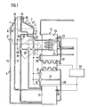
- the device for converting solar energy into heat comprises a solar collector illustrated only very schematically in the drawing, which consists of a plurality of at the Outside of a building or the like specified collector elements 1 exists.
- These can have the previously known basic structure, that is to say comprise an insulating body 2 with inclined surfaces which form an approximately right angle with respect to one another.
- a collector channel 3 is assigned to the surface facing the sun, and an absorber channel 4 is assigned to the surface extending transversely to this surface.
- Each of the two channels 3, 4 each has an inlet 5 or 6 and an outlet 7 or 8, via which each collector element 1 can be coupled with a similar adjacent collector element or connected to a heat transfer fluid network 9.
- the latter comprises a first connecting line consisting of a flow branch 10 and a return branch 11, via which the collector channel 3 can be connected either to a high-temperature store 12 or to a low-temperature store 13.
- the absorber channel 4 is connected to the low-temperature accumulator 13 via a second connecting line consisting of a? Wide flow branch 14 and a second return branch 15.
- Both the first connecting line 10, 11 and the second connecting line 14, 15 each contain a pump 16 or 17 to ensure the circulation of the heat transfer fluid.
- the first connecting line 10, 11 comprises a valve arrangement 18 which, in the illustrated example according to FIG. 1, consists of four electromagnetically actuated two-way valves 19, 20, 21, 22.
- the two-way valve 19 enables the connection of the flow branch 10 to the high-temperature accumulator 12 or the low-temperature accumulator 13.
- the two-way valves 20 and 21 are switched on one behind the other, and a branch leading from the latter to the two-way valve 22 is separated.
- the two-way valves 20, 21 and 22 enable the low-temperature accumulator 13 to be connected to the return branch 11 when reversing.
- the high-temperature accumulator 12 is bridged by the connecting branch between the valves 21 and 22.
- a heat pump 26 is switched on between the low-temperature store 13 and the high-temperature store 12. Circulation pumps 29, 30 are located in each of the two circuits 27, 28 between the stores 12, 13 and the heat pump 26. On the low-temperature store side, the heat pump 26 can be bridged by a short-circuit line 31 with a continuously openable valve 32 switched on.
- a temperature sensor 33, 34 is assigned to the high-temperature store 12 and the low-temperature store 13.
- the temperature in the collector channel 3 is determined by a temperature sensor 35 and in the absorber channel 4 a temperature sensor 36.
- the collector channel 3 is located in a known manner, not shown in the drawing, below a transparent cover on the bottom of a collector chamber 37 defined by it. To determine the temperature in a further temperature sensor 38 is provided in this collector chamber 37.
- the two-way valves 19, 20 are reversed so that the pump 16 transfers the heat transfer fluid in the short-circuit circuit via the Two-way valves 19 to 22 leads.
- the temperature measured by the temperature sensor 35 rises.
- the control device 39 determines on the basis of the measured and supplied temperature values that a certain positive temperature difference compared to that determined by the temperature sensor 33.
- the temperature of the heat transfer fluid in the high-temperature accumulator 12 is reached, it ensures that the two-way valves 21, 22 are reversed.
- the heat transfer fluid heated in the collector duct 3 then flows under the action of the pump 16 via the two-way valve 22, the heat exchanger 23 of the high-temperature accumulator 12 and the two-way valves 21. 20 and 19.
- the two-way valves 19 to 22 are reversed so that the connection between the valves 19 and 20 is interrupted and the heat transfer fluid is guided past the high-temperature accumulator 12 via the low-temperature accumulator 1.3 becomes.
- the temperature sensor 38 illustrated in the drawing in connection with the temperature sensor 35, it is also possible to determine and utilize the increasing heating by increasing the radiation energy in another way.
- a temperature sensor arrangement both at the inlet and at the outlet of the collector channel can be used to measure the temperatures present there, which are to be evaluated in the control unit.
- the measured temperature difference is predetermined Value compared to form a comparison value.
- the control unit triggers the reversal of the control valve arrangement in the sense of an opening of the short-circuit branch.
- the difference between the temperature of the heat transfer fluid at the outlet of the collector channel and the temperature of the heat transfer fluid in the high-temperature store is used to determine the point in time for the disconnection of the short-circuit branch and the simultaneous activation of the high-temperature store in the circuit.
- valve arrangement 18 shown in FIG. 1 with four two-way valves
- two temperature measurements are assumed, namely the measured temperature of the heat transfer fluid in the collector channel, namely on the output side, and the temperature in the collector chamber or instead the temperature on the inlet side of the collector channel.
- the supply of relatively cold brine brings about a cooling of the air in the collector chamber 37.
- the temperature value measured by the temperature sensor 38 thus does not correspond to the energy radiation; rather, it is falsified by air cooling. It has therefore proven to be very expedient if the temperature sensor 38 is insulated from the immediate surroundings, that is to say it is installed in the collector chamber 37 with thermal insulation.
- this temperature sensor practically measures the temperature that would result if there was no circulation of the heat transfer fluid, a "standstill temperature” is thus determined, ie temperature that would occur if the collector channel was not flowed through.
- This makes it possible to use the temperature value measured with the thermally insulated built-in temperature sensor 38 during the transition from the low-temperature storage mode to the high-temperature storage mode directly for the purpose of switching to the temporary short-circuit branch mode, ie to determine only its temperature.
- On high-temperature storage mode is only switched when the values measured by the temperature sensors 35 and 33 show that the conditions are met, namely a temperature difference of z. B. 6 ° C is reached. The high-temperature storage operation is maintained until the value falls below, then the reversal takes place again, as already described.
- the radiation intensity itself for example determined by means of a photosensor assigned to the collector elements 1 and used as a basis for the pump or valve arrangement control by the control device 39.
- the photosensor reacts very quickly to any change in the radiation intensity, so that its measured values are not comparable with those that are provided by the temperature sensors 35 and 38.
Landscapes
- Engineering & Computer Science (AREA)
- Mechanical Engineering (AREA)
- General Engineering & Computer Science (AREA)
- Sustainable Development (AREA)
- Sustainable Energy (AREA)
- Thermal Sciences (AREA)
- Chemical & Material Sciences (AREA)
- Combustion & Propulsion (AREA)
- Physics & Mathematics (AREA)
- Life Sciences & Earth Sciences (AREA)
- Heat-Pump Type And Storage Water Heaters (AREA)
- Physical Or Chemical Processes And Apparatus (AREA)
- Photovoltaic Devices (AREA)
- Diaphragms For Electromechanical Transducers (AREA)
- Engine Equipment That Uses Special Cycles (AREA)
- Crystals, And After-Treatments Of Crystals (AREA)
- Control Of Temperature (AREA)
- Central Heating Systems (AREA)
Applications Claiming Priority (2)
| Application Number | Priority Date | Filing Date | Title |
|---|---|---|---|
| DE3925145A DE3925145A1 (de) | 1989-07-28 | 1989-07-28 | Verfahren zur umsetzung von sonnenenergie in waerme sowie einrichtung zur durchfuehrung des verfahrens |
| DE3925145 | 1989-07-28 |
Publications (2)
| Publication Number | Publication Date |
|---|---|
| EP0484358A1 EP0484358A1 (de) | 1992-05-13 |
| EP0484358B1 true EP0484358B1 (de) | 1993-03-03 |
Family
ID=6386118
Family Applications (1)
| Application Number | Title | Priority Date | Filing Date |
|---|---|---|---|
| EP90910708A Expired - Lifetime EP0484358B1 (de) | 1989-07-28 | 1990-07-30 | Verfahren zur umsetzung von sonnenenergie in warme sowie einrichtung zur durchfuhrung des verfahrens |
Country Status (9)
| Country | Link |
|---|---|
| US (1) | US5224466A (da) |
| EP (1) | EP0484358B1 (da) |
| JP (1) | JP3041040B2 (da) |
| AT (1) | ATE86377T1 (da) |
| CA (1) | CA2065391A1 (da) |
| DE (2) | DE3925145A1 (da) |
| DK (1) | DK0484358T3 (da) |
| ES (1) | ES2040127T3 (da) |
| WO (1) | WO1991002199A1 (da) |
Families Citing this family (24)
| Publication number | Priority date | Publication date | Assignee | Title |
|---|---|---|---|---|
| JPH07234020A (ja) * | 1994-02-24 | 1995-09-05 | Showa Alum Corp | ハイブリッド式ソーラーシステム |
| AT403842B (de) * | 1994-08-03 | 1998-05-25 | Vaillant Gmbh | Heizungsanlage mit zwei brauchwasserspeichern |
| AU2006274484B2 (en) * | 2005-07-29 | 2011-04-21 | Rheem Australia Pty Limited | Thermo-siphon restrictor valve |
| US20080156317A1 (en) * | 2007-01-03 | 2008-07-03 | Pitaya Yangpichit | Solar chimney for daytime and nighttime use |
| DE102007052234A1 (de) * | 2007-10-22 | 2009-04-23 | Deutsches Zentrum für Luft- und Raumfahrt e.V. | Verfahren zum Betreiben eines solarthermischen Kraftwerks und solarthermisches Kraftwerk |
| ITBO20070760A1 (it) * | 2007-11-16 | 2009-05-17 | O T M A S N C Di Spaggiari & C | Impianto combinato con pannelli solari e caldaia murale |
| DE202008007796U1 (de) * | 2008-06-11 | 2008-09-11 | Paw Gmbh & Co. Kg | Solarthermische Anlage umfassend zumindest einen Sonnenkollektor |
| DE102008049954A1 (de) * | 2008-10-02 | 2010-04-08 | Thomas Hahn | Vorrichtung zur Nutzung und Speicherung von Solar- und Umweltwärme, ganzjährig effizient nutzbar |
| US8534068B2 (en) * | 2010-01-15 | 2013-09-17 | Pitaya Yangpichit | Solar chimney with wind turbine |
| US20120090597A1 (en) * | 2010-11-01 | 2012-04-19 | General Electric Company | Pump drained solar water heating system |
| CH705478A1 (fr) * | 2011-09-09 | 2013-03-15 | Granit Sa | Dispositif pour la récupération et/ou le stockage des énergies renouvelables. |
| DE102011086223A1 (de) * | 2011-11-11 | 2013-05-16 | Siemens Aktiengesellschaft | Wärmeträgermedium-Kreislauf mit Überlaufbehälter, Verfahren zum Transport von Wärmeträgermedium mit Hilfe des Wärmeträgermedium-Kreislaufs und Verwendung des Wärmeträgermedium-Kreislaufs |
| WO2013100865A1 (en) | 2011-12-30 | 2013-07-04 | Pitaya Yangpichit | Solar chimney with external vertical axis wind turbine |
| CN102538195A (zh) * | 2012-01-20 | 2012-07-04 | 沈雁茜 | 一种太阳能异聚态热利用系统及其工作方法 |
| ITMO20120138A1 (it) * | 2012-05-28 | 2013-11-29 | Ca Pi S S R L | Metodo di intervento per incrementare l'efficienza di un impianto di riscaldamento. |
| ITMO20120137A1 (it) * | 2012-05-28 | 2013-11-29 | Ca Pi S S R L | Impianto per la produzione di acqua calda. |
| DE102013003206A1 (de) * | 2013-02-26 | 2014-08-28 | Franz Maierhofer | Fernwärmeübergabevorrichtung für ein Gebäude sowie Fernwärmesystem zur Versorgung von Gebäuden mit Wärmeenergie |
| RU2538347C1 (ru) * | 2013-06-19 | 2015-01-10 | Федеральное государственное бюджетное образовательное учреждение высшего профессионального образования "Юго-Западный государственный университет" (ЮЗГУ) | Система гелиотеплохладоснабжения |
| CN103453679B (zh) * | 2013-08-15 | 2018-04-20 | 常州海卡太阳能热泵有限公司 | 家用壁挂式平板太阳能热泵热水器的控制方法 |
| AT516313B1 (de) * | 2014-06-20 | 2016-06-15 | Hans-Georg Benken | Verfahren und Einrichtung zum Betrieb von Wärmegewinnungsanlagen mit Wärmepumpe und Wärmetauscher |
| DE102016112784A1 (de) * | 2016-07-12 | 2018-01-18 | Viessmann Werke Gmbh & Co Kg | Kollektorfeld, Energieversorgungssystem mit einem Kollektorfeld sowie Verfahren zum Betreiben eines Energieversorgungssystems |
| CN106287918A (zh) * | 2016-08-26 | 2017-01-04 | 田幼华 | 一种跨季节太阳能储能供暖系统及其控制方法 |
| CN111765506B (zh) * | 2020-07-14 | 2022-07-08 | 戢森 | 智能管网控制方法及系统 |
| CN113983535A (zh) * | 2021-10-29 | 2022-01-28 | 上海勘测设计研究院有限公司 | 模块式智慧型清洁供暖站 |
Family Cites Families (9)
| Publication number | Priority date | Publication date | Assignee | Title |
|---|---|---|---|---|
| DE2554975A1 (de) * | 1975-12-06 | 1977-06-16 | Bbc Brown Boveri & Cie | Verfahren zur temperaturgesteuerten warmwasserbereitung durch sonnenenergie |
| FR2404181A1 (fr) * | 1977-09-27 | 1979-04-20 | Messier Fa | Installation de chauffage a capteur solaire |
| US4251997A (en) * | 1979-04-02 | 1981-02-24 | Borg-Warner Corporation | Control of absorption systems energized from plural storage tanks maintained at different temperatures |
| DE3001550A1 (de) * | 1980-01-17 | 1981-07-23 | Joh. Vaillant Gmbh U. Co, 5630 Remscheid | Steuerverfahren fuer eine steuervorrichtung einer sonnenkollektorwaermequelle |
| DE3004324A1 (de) * | 1980-02-06 | 1981-08-13 | Josef 8492 Neustadt Probst | Vorrichtung zur regelung einer heizungsanlage mit wenigstens einer einrichtung zur gewinnung von waerme aus einem absorber |
| FR2496847A1 (fr) * | 1980-12-19 | 1982-06-25 | Mecelec Sa | Perfectionnements aux installations de chauffage utilisant la chaleur rayonnee par le soleil |
| DE3048499A1 (de) * | 1980-12-22 | 1982-07-08 | Hermann Ing.(grad.) 8121 Antdorf Kirchmayer | Einrichtung zur umsetzung von sonnenenergie in waerme |
| CA1203133A (en) * | 1982-04-21 | 1986-04-15 | Hermann Kirchmayer | Solar collector and absorber |
| US4527618A (en) * | 1982-09-29 | 1985-07-09 | Solar Decisions, Inc. | Solar energy storage and distribution system with heat pump assist |
-
1989
- 1989-07-28 DE DE3925145A patent/DE3925145A1/de not_active Withdrawn
-
1990
- 1990-07-30 US US07/820,697 patent/US5224466A/en not_active Expired - Fee Related
- 1990-07-30 WO PCT/EP1990/001243 patent/WO1991002199A1/de not_active Ceased
- 1990-07-30 JP JP2510692A patent/JP3041040B2/ja not_active Expired - Lifetime
- 1990-07-30 DK DK90910708.8T patent/DK0484358T3/da active
- 1990-07-30 ES ES199090910708T patent/ES2040127T3/es not_active Expired - Lifetime
- 1990-07-30 EP EP90910708A patent/EP0484358B1/de not_active Expired - Lifetime
- 1990-07-30 DE DE9090910708T patent/DE59000989D1/de not_active Expired - Fee Related
- 1990-07-30 CA CA002065391A patent/CA2065391A1/en not_active Abandoned
- 1990-07-30 AT AT90910708T patent/ATE86377T1/de active
Also Published As
| Publication number | Publication date |
|---|---|
| ATE86377T1 (de) | 1993-03-15 |
| JPH05501912A (ja) | 1993-04-08 |
| JP3041040B2 (ja) | 2000-05-15 |
| WO1991002199A1 (de) | 1991-02-21 |
| DE59000989D1 (de) | 1993-04-08 |
| DK0484358T3 (da) | 1993-04-05 |
| CA2065391A1 (en) | 1991-01-29 |
| EP0484358A1 (de) | 1992-05-13 |
| DE3925145A1 (de) | 1991-02-07 |
| US5224466A (en) | 1993-07-06 |
| ES2040127T3 (es) | 1993-10-01 |
Similar Documents
| Publication | Publication Date | Title |
|---|---|---|
| WO1991002199A1 (de) | Verfahren zur umsetzung von sonnenenergie in warme sowie einrichtung zur durchfuhrung des verfahrens | |
| DE2619744C2 (de) | Anlage zum Beheizen eines Gebäudes und zur Warmwasserbereitung | |
| DE1604205A1 (de) | Klimaanlage | |
| DE102009025596B4 (de) | System zum Liefern von heißem Wasser | |
| WO2012075975A1 (de) | Heiz-/kühleinrichtung und verfahren zum betreiben einer heiz-/kühleinrichtung | |
| DE3112228C2 (de) | Kälteanlage mit Warmwassererzeugung | |
| EP0006211A1 (de) | Vorrichtung zur Warmwasserbereitung mittels Sonnenenergie | |
| DE3012308A1 (de) | Steuersystem fuer eine absorptionskaeltemaschine, absorptionskaeltemaschine und verfahren zu deren betrieb | |
| DE3344608C2 (da) | ||
| DE2919524A1 (de) | Anlage zur gewinnung thermischer energie unter benuetzung der sonnenwaerme | |
| DE2856018A1 (de) | Anordnung zur regelung der waermeverteilung in einem solarhaus | |
| DE2800173A1 (de) | Anlage zur verwertung von sonnenenergie fuer die erwaermung von wasser | |
| DE4312150C2 (de) | Verfahren zum Einstellen der Förderleistung einer Umwälzpumpe | |
| DE2846797A1 (de) | Vorrichtung zur waermerueckgewinnung | |
| DE102015121188A1 (de) | Fahrzeug-Heizungs-, -Lüftungs- und -Klimasystem und Kältemittelsammler für ein Fahrzeug-Heizungs-, -Lüftungs- und -Klimasystem | |
| EP0033756A1 (de) | Verfahren und Vorrichtung zur Regelung einer Heizungsanlage mit einer Einrichtung zur Gewinnung von Wärme aus einem Absorber | |
| EP0092251B1 (de) | Einrichtung zur Umsetzung von Sonnenenergie in Wärme | |
| AT413302B (de) | Umweltwärmequelle für eine wärmepumpe | |
| DE10011538B4 (de) | Einrichtung zur Kühlung von Nutz- und Brauchwasser | |
| DE4135509C2 (de) | Verfahren zur Regelung einer in einem Umwälzkreislauf einer Heizungsanlage eingesetzten, drehzahlregelbaren Umwälzpumpe | |
| DE19535891A1 (de) | Elektrische Heizzentrale | |
| DE19906523A1 (de) | Heizungskreislauf für Kraftfahrzeuge | |
| EP0358041B1 (de) | Verfahren zum Beheizen eines Gebäudes und Heizungsanlage | |
| DE3019475A1 (de) | System zur waermegewinnung aus solar- bzw. umgebungsenergie | |
| DE1803248A1 (de) | Verfahren und Vorrichtung zur Regelung der Vorlauftemperatur eines Heizungskreislaufes |
Legal Events
| Date | Code | Title | Description |
|---|---|---|---|
| PUAI | Public reference made under article 153(3) epc to a published international application that has entered the european phase |
Free format text: ORIGINAL CODE: 0009012 |
|
| 17P | Request for examination filed |
Effective date: 19910102 |
|
| AK | Designated contracting states |
Kind code of ref document: A1 Designated state(s): AT BE CH DE DK ES FR GB IT LI LU NL SE |
|
| 17Q | First examination report despatched |
Effective date: 19920601 |
|
| GRAA | (expected) grant |
Free format text: ORIGINAL CODE: 0009210 |
|
| AK | Designated contracting states |
Kind code of ref document: B1 Designated state(s): AT BE CH DE DK ES FR GB IT LI LU NL SE |
|
| REF | Corresponds to: |
Ref document number: 86377 Country of ref document: AT Date of ref document: 19930315 Kind code of ref document: T |
|
| ITF | It: translation for a ep patent filed | ||
| REG | Reference to a national code |
Ref country code: DK Ref legal event code: T3 |
|
| REF | Corresponds to: |
Ref document number: 59000989 Country of ref document: DE Date of ref document: 19930408 |
|
| GBT | Gb: translation of ep patent filed (gb section 77(6)(a)/1977) |
Effective date: 19930315 |
|
| PGFP | Annual fee paid to national office [announced via postgrant information from national office to epo] |
Ref country code: BE Payment date: 19930621 Year of fee payment: 4 |
|
| ET | Fr: translation filed | ||
| PGFP | Annual fee paid to national office [announced via postgrant information from national office to epo] |
Ref country code: LU Payment date: 19930707 Year of fee payment: 4 |
|
| PGFP | Annual fee paid to national office [announced via postgrant information from national office to epo] |
Ref country code: SE Payment date: 19930721 Year of fee payment: 4 |
|
| PGFP | Annual fee paid to national office [announced via postgrant information from national office to epo] |
Ref country code: NL Payment date: 19930731 Year of fee payment: 4 |
|
| PGFP | Annual fee paid to national office [announced via postgrant information from national office to epo] |
Ref country code: DK Payment date: 19930930 Year of fee payment: 4 |
|
| REG | Reference to a national code |
Ref country code: ES Ref legal event code: FG2A Ref document number: 2040127 Country of ref document: ES Kind code of ref document: T3 |
|
| EPTA | Lu: last paid annual fee | ||
| PLBE | No opposition filed within time limit |
Free format text: ORIGINAL CODE: 0009261 |
|
| STAA | Information on the status of an ep patent application or granted ep patent |
Free format text: STATUS: NO OPPOSITION FILED WITHIN TIME LIMIT |
|
| 26N | No opposition filed | ||
| PG25 | Lapsed in a contracting state [announced via postgrant information from national office to epo] |
Ref country code: LU Free format text: LAPSE BECAUSE OF NON-PAYMENT OF DUE FEES Effective date: 19940730 Ref country code: DK Effective date: 19940730 |
|
| REG | Reference to a national code |
Ref country code: DK Ref legal event code: EBP |
|
| PG25 | Lapsed in a contracting state [announced via postgrant information from national office to epo] |
Ref country code: SE Effective date: 19940731 Ref country code: BE Effective date: 19940731 |
|
| BERE | Be: lapsed |
Owner name: KIRCHMAYER LEONHARD Effective date: 19940731 |
|
| EUG | Se: european patent has lapsed |
Ref document number: 90910708.8 Effective date: 19950210 |
|
| PG25 | Lapsed in a contracting state [announced via postgrant information from national office to epo] |
Ref country code: NL Effective date: 19950201 |
|
| NLV4 | Nl: lapsed or anulled due to non-payment of the annual fee | ||
| EUG | Se: european patent has lapsed |
Ref document number: 90910708.8 |
|
| PGFP | Annual fee paid to national office [announced via postgrant information from national office to epo] |
Ref country code: GB Payment date: 19990728 Year of fee payment: 10 Ref country code: AT Payment date: 19990728 Year of fee payment: 10 |
|
| PGFP | Annual fee paid to national office [announced via postgrant information from national office to epo] |
Ref country code: FR Payment date: 19990729 Year of fee payment: 10 Ref country code: ES Payment date: 19990729 Year of fee payment: 10 |
|
| PGFP | Annual fee paid to national office [announced via postgrant information from national office to epo] |
Ref country code: CH Payment date: 19990804 Year of fee payment: 10 |
|
| PGFP | Annual fee paid to national office [announced via postgrant information from national office to epo] |
Ref country code: DE Payment date: 19990930 Year of fee payment: 10 |
|
| PG25 | Lapsed in a contracting state [announced via postgrant information from national office to epo] |
Ref country code: GB Free format text: LAPSE BECAUSE OF NON-PAYMENT OF DUE FEES Effective date: 20000730 Ref country code: AT Free format text: LAPSE BECAUSE OF NON-PAYMENT OF DUE FEES Effective date: 20000730 |
|
| PG25 | Lapsed in a contracting state [announced via postgrant information from national office to epo] |
Ref country code: LI Free format text: LAPSE BECAUSE OF NON-PAYMENT OF DUE FEES Effective date: 20000731 Ref country code: ES Free format text: LAPSE BECAUSE OF NON-PAYMENT OF DUE FEES Effective date: 20000731 Ref country code: CH Free format text: LAPSE BECAUSE OF NON-PAYMENT OF DUE FEES Effective date: 20000731 |
|
| REG | Reference to a national code |
Ref country code: CH Ref legal event code: PL |
|
| GBPC | Gb: european patent ceased through non-payment of renewal fee |
Effective date: 20000730 |
|
| PG25 | Lapsed in a contracting state [announced via postgrant information from national office to epo] |
Ref country code: FR Free format text: LAPSE BECAUSE OF NON-PAYMENT OF DUE FEES Effective date: 20010330 |
|
| REG | Reference to a national code |
Ref country code: FR Ref legal event code: ST |
|
| PG25 | Lapsed in a contracting state [announced via postgrant information from national office to epo] |
Ref country code: DE Free format text: LAPSE BECAUSE OF NON-PAYMENT OF DUE FEES Effective date: 20010501 |
|
| REG | Reference to a national code |
Ref country code: ES Ref legal event code: FD2A Effective date: 20010810 |
|
| PG25 | Lapsed in a contracting state [announced via postgrant information from national office to epo] |
Ref country code: IT Free format text: LAPSE BECAUSE OF NON-PAYMENT OF DUE FEES;WARNING: LAPSES OF ITALIAN PATENTS WITH EFFECTIVE DATE BEFORE 2007 MAY HAVE OCCURRED AT ANY TIME BEFORE 2007. THE CORRECT EFFECTIVE DATE MAY BE DIFFERENT FROM THE ONE RECORDED. Effective date: 20050730 |