EP0484258A1 - Öffnungs- und Schliessvorrichtung einer Flügel drehbar auf 180 Graden und solche Vorrichtung umfassende Anlage - Google Patents
Öffnungs- und Schliessvorrichtung einer Flügel drehbar auf 180 Graden und solche Vorrichtung umfassende Anlage Download PDFInfo
- Publication number
- EP0484258A1 EP0484258A1 EP91420387A EP91420387A EP0484258A1 EP 0484258 A1 EP0484258 A1 EP 0484258A1 EP 91420387 A EP91420387 A EP 91420387A EP 91420387 A EP91420387 A EP 91420387A EP 0484258 A1 EP0484258 A1 EP 0484258A1
- Authority
- EP
- European Patent Office
- Prior art keywords
- leaf
- connecting rod
- opening
- rotation
- axis
- Prior art date
- Legal status (The legal status is an assumption and is not a legal conclusion. Google has not performed a legal analysis and makes no representation as to the accuracy of the status listed.)
- Withdrawn
Links
- 238000009434 installation Methods 0.000 title claims description 7
- 230000002427 irreversible effect Effects 0.000 claims description 3
- 230000005540 biological transmission Effects 0.000 claims description 2
- 238000009432 framing Methods 0.000 description 2
- 238000005259 measurement Methods 0.000 description 2
- 230000000295 complement effect Effects 0.000 description 1
- 230000007423 decrease Effects 0.000 description 1
- 238000010586 diagram Methods 0.000 description 1
- 238000006073 displacement reaction Methods 0.000 description 1
- 230000002441 reversible effect Effects 0.000 description 1
Images


Classifications
-
- F—MECHANICAL ENGINEERING; LIGHTING; HEATING; WEAPONS; BLASTING
- F16—ENGINEERING ELEMENTS AND UNITS; GENERAL MEASURES FOR PRODUCING AND MAINTAINING EFFECTIVE FUNCTIONING OF MACHINES OR INSTALLATIONS; THERMAL INSULATION IN GENERAL
- F16H—GEARING
- F16H19/00—Gearings comprising essentially only toothed gears or friction members and not capable of conveying indefinitely-continuing rotary motion
- F16H19/001—Gearings comprising essentially only toothed gears or friction members and not capable of conveying indefinitely-continuing rotary motion for conveying reciprocating or limited rotary motion
-
- E—FIXED CONSTRUCTIONS
- E05—LOCKS; KEYS; WINDOW OR DOOR FITTINGS; SAFES
- E05F—DEVICES FOR MOVING WINGS INTO OPEN OR CLOSED POSITION; CHECKS FOR WINGS; WING FITTINGS NOT OTHERWISE PROVIDED FOR, CONCERNED WITH THE FUNCTIONING OF THE WING
- E05F15/00—Power-operated mechanisms for wings
- E05F15/60—Power-operated mechanisms for wings using electrical actuators
- E05F15/603—Power-operated mechanisms for wings using electrical actuators using rotary electromotors
- E05F15/611—Power-operated mechanisms for wings using electrical actuators using rotary electromotors for swinging wings
- E05F15/63—Power-operated mechanisms for wings using electrical actuators using rotary electromotors for swinging wings operated by swinging arms
-
- E—FIXED CONSTRUCTIONS
- E05—LOCKS; KEYS; WINDOW OR DOOR FITTINGS; SAFES
- E05Y—INDEXING SCHEME ASSOCIATED WITH SUBCLASSES E05D AND E05F, RELATING TO CONSTRUCTION ELEMENTS, ELECTRIC CONTROL, POWER SUPPLY, POWER SIGNAL OR TRANSMISSION, USER INTERFACES, MOUNTING OR COUPLING, DETAILS, ACCESSORIES, AUXILIARY OPERATIONS NOT OTHERWISE PROVIDED FOR, APPLICATION THEREOF
- E05Y2201/00—Constructional elements; Accessories therefor
- E05Y2201/40—Motors; Magnets; Springs; Weights; Accessories therefor
- E05Y2201/43—Motors
- E05Y2201/434—Electromotors; Details thereof
-
- E—FIXED CONSTRUCTIONS
- E05—LOCKS; KEYS; WINDOW OR DOOR FITTINGS; SAFES
- E05Y—INDEXING SCHEME ASSOCIATED WITH SUBCLASSES E05D AND E05F, RELATING TO CONSTRUCTION ELEMENTS, ELECTRIC CONTROL, POWER SUPPLY, POWER SIGNAL OR TRANSMISSION, USER INTERFACES, MOUNTING OR COUPLING, DETAILS, ACCESSORIES, AUXILIARY OPERATIONS NOT OTHERWISE PROVIDED FOR, APPLICATION THEREOF
- E05Y2201/00—Constructional elements; Accessories therefor
- E05Y2201/60—Suspension or transmission members; Accessories therefor
- E05Y2201/606—Accessories therefor
- E05Y2201/618—Transmission ratio variation
-
- E—FIXED CONSTRUCTIONS
- E05—LOCKS; KEYS; WINDOW OR DOOR FITTINGS; SAFES
- E05Y—INDEXING SCHEME ASSOCIATED WITH SUBCLASSES E05D AND E05F, RELATING TO CONSTRUCTION ELEMENTS, ELECTRIC CONTROL, POWER SUPPLY, POWER SIGNAL OR TRANSMISSION, USER INTERFACES, MOUNTING OR COUPLING, DETAILS, ACCESSORIES, AUXILIARY OPERATIONS NOT OTHERWISE PROVIDED FOR, APPLICATION THEREOF
- E05Y2201/00—Constructional elements; Accessories therefor
- E05Y2201/60—Suspension or transmission members; Accessories therefor
- E05Y2201/622—Suspension or transmission members elements
- E05Y2201/71—Toothed gearing
- E05Y2201/716—Pinions
-
- E—FIXED CONSTRUCTIONS
- E05—LOCKS; KEYS; WINDOW OR DOOR FITTINGS; SAFES
- E05Y—INDEXING SCHEME ASSOCIATED WITH SUBCLASSES E05D AND E05F, RELATING TO CONSTRUCTION ELEMENTS, ELECTRIC CONTROL, POWER SUPPLY, POWER SIGNAL OR TRANSMISSION, USER INTERFACES, MOUNTING OR COUPLING, DETAILS, ACCESSORIES, AUXILIARY OPERATIONS NOT OTHERWISE PROVIDED FOR, APPLICATION THEREOF
- E05Y2400/00—Electronic control; Electrical power; Power supply; Power or signal transmission; User interfaces
- E05Y2400/10—Electronic control
- E05Y2400/32—Position control, detection or monitoring
- E05Y2400/35—Position control, detection or monitoring related to specific positions
- E05Y2400/354—End positions
-
- E—FIXED CONSTRUCTIONS
- E05—LOCKS; KEYS; WINDOW OR DOOR FITTINGS; SAFES
- E05Y—INDEXING SCHEME ASSOCIATED WITH SUBCLASSES E05D AND E05F, RELATING TO CONSTRUCTION ELEMENTS, ELECTRIC CONTROL, POWER SUPPLY, POWER SIGNAL OR TRANSMISSION, USER INTERFACES, MOUNTING OR COUPLING, DETAILS, ACCESSORIES, AUXILIARY OPERATIONS NOT OTHERWISE PROVIDED FOR, APPLICATION THEREOF
- E05Y2400/00—Electronic control; Electrical power; Power supply; Power or signal transmission; User interfaces
- E05Y2400/10—Electronic control
- E05Y2400/50—Fault detection
- E05Y2400/51—Fault detection of position, of back drive
-
- E—FIXED CONSTRUCTIONS
- E05—LOCKS; KEYS; WINDOW OR DOOR FITTINGS; SAFES
- E05Y—INDEXING SCHEME ASSOCIATED WITH SUBCLASSES E05D AND E05F, RELATING TO CONSTRUCTION ELEMENTS, ELECTRIC CONTROL, POWER SUPPLY, POWER SIGNAL OR TRANSMISSION, USER INTERFACES, MOUNTING OR COUPLING, DETAILS, ACCESSORIES, AUXILIARY OPERATIONS NOT OTHERWISE PROVIDED FOR, APPLICATION THEREOF
- E05Y2600/00—Mounting or coupling arrangements for elements provided for in this subclass
- E05Y2600/40—Mounting location; Visibility of the elements
- E05Y2600/46—Mounting location; Visibility of the elements in or on the wing
-
- E—FIXED CONSTRUCTIONS
- E05—LOCKS; KEYS; WINDOW OR DOOR FITTINGS; SAFES
- E05Y—INDEXING SCHEME ASSOCIATED WITH SUBCLASSES E05D AND E05F, RELATING TO CONSTRUCTION ELEMENTS, ELECTRIC CONTROL, POWER SUPPLY, POWER SIGNAL OR TRANSMISSION, USER INTERFACES, MOUNTING OR COUPLING, DETAILS, ACCESSORIES, AUXILIARY OPERATIONS NOT OTHERWISE PROVIDED FOR, APPLICATION THEREOF
- E05Y2900/00—Application of doors, windows, wings or fittings thereof
- E05Y2900/10—Application of doors, windows, wings or fittings thereof for buildings or parts thereof
- E05Y2900/13—Type of wing
- E05Y2900/146—Shutters
Definitions
- the present invention relates to devices, in the general sense, designed to ensure the opening and closing of at least one leaf or panel pivoting over an angular range of 180 ° and constituting, for example, a partial or complete concealment element an opening, such as a window or door.
- the invention is particularly suitable for equipping pivoting shutters, of various shapes and natures, having one leaf or two leaves.
- a device for controlling the opening and closing of a pivoting leaf comprising a geared motor capable of driving in rotation a first connecting rod around a vertical axis.
- This first connecting rod is articulated with one end of a second connecting rod, the other end of which is connected to a fixed pivot mounted on the leaf.
- the gear motor is connected to the first connecting rod by means of a linkage which is capable of returning the rotational movement to a similar device equipping a second leaf.
- Such a device is intended to be installed between the vertical uprights of a window, in proximity relationship to the top and bottom crosspieces of the window. Such a device has, in practice, many drawbacks.
- Another drawback of this device relates to the simultaneous control of the two leaves produced by means of a common linkage, so that it does not appear possible to dissociate the opening or closing, complete or partial, of the two leaves.
- the present invention aims to remedy the drawbacks set out above by proposing a device for controlling the opening and closing of a leaf pivoting over an angular range of 180 ° and capable of being installed on the leaf of an opening which was not designed to receive this device without, however, detracting from the aesthetics of the opening and the passage of light.
- the object of the invention also aims to propose a device capable of ensuring effective locking of the leaf, whether in the closed, open or intermediate position between these two extreme positions.
- An additional object of the invention aims to provide a device intended to equip a pivoting leaf of any kind and having ease of assembly.
- the invention also aims to propose a device suitable for ensuring independent control of the two leaves equipping an opening.
- the device according to the invention for controlling the opening and closing of a leaf pivoting over an angular range of 180 ° around a hinge axis, is of the type comprising a geared motor capable to be driven in rotation about an axis, a first connecting rod articulated along a corresponding axis with one end of a second connecting rod whose other end is connected to a fixed pivot, the axes of rotation being substantially parallel to one another.
- the device according to the invention is characterized in that the gear motor is locked in rotation with the first connecting rod and is mounted, relative to the opening, on the internal face of the leaf and in that the fixed pivot is adapted on the framing of the opening, so that in the leaf closed position the axes occupy neighboring positions and are on a common line substantially perpendicular to the plane of the leaf, to ensure locking of the leaf.
- the object of the invention also aims to propose a installation for two leaves of an opening comprising a control circuit common to the two motor-reduction gates for controlling the leaves and to which is associated a delay means making it possible to offset the rotation of the right leaf relative to that of the left leaf, when closing of the leaves, and vice versa, when opening the leaves.
- Fig. 1 is a perspective view showing a window with two leaves on which the control device according to the invention is adapted.
- Figs. 2 A to 2 E are top views showing the device in different characteristic positions.
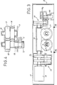
- Fig. 3 is a sectional view of the geared motor used in the control device according to the invention.
- Fig. 4 is an elevational view taken substantially along lines IV-IV of FIG. 3 .
- Fig. 5 shows curves showing the motor torque exerted on the leaf as a function of its opening angle.
- Fig. 6 is a sectional view taken substantially along the lines VI-VI of FIG. 2 B.
- Fig. 7 is a functional diagram showing a characteristic detail of the control device according to the invention.
- Fig. 1 illustrates an opening 1 , such as a window equipped with two panels, shutters or, in general, leaves 2 each provided with a device 3 according to the invention, ensuring their control during opening and closing.
- each device 3 comprises a geared motor 4 intended to be adapted, by any suitable means, to the leaf 2 on its internal face relative to the opening 1 and, for example, in its lower part.
- the gear motor 4 is intended to drive in rotation a first connecting rod 5 angularly wedged by one end 51 with the output shaft of the gear motor, rotating around a vertical axis C which is substantially parallel to the axis of articulation O of leaf 2 .
- the first connecting rod 5 is articulated, by its opposite end 52 , at one end 61 of a second connecting rod 6 , around an axis of articulation B.
- the opposite end 62 of the connecting rod 6 is connected to a fixed pivot 7 having a general axis A.
- the pivot 7 is fixed to the frame 11 externally bordering the opening 1 .
- the pivot 7 is fixed to the part of the frame forming the window sill.
- the axes A , B , C and O are substantially parallel to each other, so that your connecting rods 5 and 6 move in a plane substantially perpendicular to the plane of the leaf 2 .
- the sum of the lengths of the connecting rods 5 and 6 , taken respectively between the axes CB and BA , is greater than the sum of the measures CO and OA , so as to allow pivoting of the leaf 2 over an angular range of 180 ° from an open position shown in fig. 2 A to a closed position illustrated in fig. 2 D , passing through intermediate positions shown in FIGS. 2 B and 2 C.
- the fixed pivot 7 is adapted on the frame, so that in the leaf closed position, the axes A and C occupy neighboring positions and are located on a common line l extending substantially perpendicular to the plane of leaf 2 .
- the angle ⁇ taken between the lines AB and BC , has a value of less than 30 ° and, advantageously, of the order of ten degrees and preferably the closest to zero.
- the connecting rods 5 and 6 have identical lengths AB and CB and therefore extend according to directions substantially parallel to the plane of the leaf, when the latter occupies the closed position ( fig. 2 D ).
- the pivot 7 is positioned so as to extend as close as possible to the axis C , that is to say to tend to be coincident with the axis C to obtain maximum locking.
- the AC / CB measurement ratio is less than 1/4 in the closed position.
- the gear motor is controlled beyond the position illustrated in FIG. 2 D for which the connecting rod 5 has undergone a rotation of 180 ° from the open position.
- the gear motor is controlled over a consecutive angular range limited to a few degrees, so that the connecting rod 6 is under mechanical tension under the action of the first connecting rod 5 .
- This position shown in fig. 2 E in which the connecting rod 5 has moved closer to the leaf, therefore constitutes a leaf locking position offering maximum inviolability.
- This position is preferably detected by a position sensor 10 fixed on the gear motor and capable of delivering a signal usable by an anti-theft installation when the latter detects the absence of the connecting rod 5 , in the case where the leaf 2 is strongly forced to open.
- the gear motor 4 is integrated inside a housing 11 fixed on the internal part of the leaf.
- the gear motor 4 comprises a motor member 12 , such as a direct current electric motor, coupled in rotation with a reduction stage 13 , the output pinion 131 of which is angularly wedged with an endless screw 14 .
- This screw 14 is intended to mesh, irreversibly, with a toothed wheel 15 mounted on a shaft 16 receiving a first meshing pinion 17 cooperating with a second pinion 18 .
- each pinion 17 , 18 has a pitch radius corresponding to a logarithmic spiral, as it appears more precisely in FIG. 3 .
- the transmission ratio of this pair of pinions varies from: R r at r R to obtain a report: (( R r ) 2 with r being the distance between the center of rotation t and the point of engagement and R the complementary diametral measurement taken between the center of rotation and the point placed on the pitch radius.
- curve A makes it possible to observe, in the absence of the pinions 17, 18 , that the torque N (in N / m), reduced to the axis of rotation O of the leaf, decreases sharply when the opening angle ⁇ of the leaf exceeds 90 °.
- the implementation of the pair of pinions 17, 18 makes it possible to obtain, beyond an opening angle equal to 90 °, greater torques, corresponding to the curve B.
- the pinion 18 is carried by a shaft 19 projecting from the housing 11 and on which the first connecting rod 5 is locked in rotation. It should be noted that this connecting rod is mounted on the axis 19 by means of a removable clamping member 21 .
- the 52 end of the connecting rod 5 is shaped to present a yoke whose arms are crossed by a pin 23 , of general axis B. The pin 23 passes through a ball joint 24 , interposed between the two arms of the yoke and fitted to the end 61 of the second connecting rod 6 .
- the 62 end of this connecting rod also includes a 241 ball joint mounted on the pivot 7 of general axis A and anchored securely on the edge 1ord of the opening, by all appropriate means.
- the connecting rod 5 is locked in axial displacement on the pivot 7 , by means of a removable clamping member 27 .
- ball joints 24 and 241 makes it possible to compensate for the errors of flatness between the two connecting rods, which may occur during assembly of the device, but also due to the inclination generally presented by the edges of the openings.
- the connecting rod 6 must be removed, its removal can be carried out easily after the removal of the member 27 , due to the presence of the ball joints.
- the screw 14 is equipped with a system 31 of wheels and toothed pinions, the output pinion 311 of which is mounted on a shaft 32 accessible from the outside of the housing 11 .
- This shaft 32 is capable of being moved axially so as to mesh with the wheels and pinions of the system 31 .
- the shaft 32 can therefore be controlled in rotation, by means of a crank making it possible to control the opening of the leaves.
- Each drive member 12 is associated with a detector 35 making it possible to measure the intensity of the direct current supplying this drive member ( FIG. 7 ).
- This detector is connected to a control circuit 36 comprising a control and management unit 37 connected to a power switching circuit 38 supplied by a voltage source 39 . If the current intensity measured by the detector 35 exceeds a set value, the unit 37 controls the shutdown of the associated motor member.
- Such an arrangement provides operational safety, insofar as, if an obstacle prevents the leaf from closing, the operation of the motor member is stopped. It should be noted that exceeding this setpoint is also used to stop the motor when the leaf reaches the open or closed position.
- the management unit 37 is controlled by a control switch 40 placed inside the volume closed by opening 2 .
- the control circuit 36 may be common to two control devices according to the invention.
- the management unit 37 includes timing means making it possible to offset the movement of the right leaf relative to that of the left leaf, when the leaves are closed, so that the left leaf cooperates with the rebate 21 carried generally by the right leaf. Of course, a reverse command is carried out when these same leaves are opened.
- the unit 37 receives control commands from the switch 40 making it possible, from specific orders, to drive the gearmotors independently, so as to allow independent or partial concealment between the two leaves.
- the device according to the invention therefore offers the advantage of being able to be easily adapted to a leaf of any kind and of any shape, requiring no particular arrangement at the level thereof or at the level of the framing of the opening in front be equipped with such a device.
- a device makes it possible to obtain effective locking in the leaf closed position and allows the leaf to be fully opened, even in the event of strong gales.
- provision may be made for installing an installation in which each leaf is equipped with a geared motor associated with a common control circuit adapted to ensure independent control of the two. leaves.
- the leaves can be placed independently of one another in intermediate positions allowing a multitude of possibilities for concealing the opening 1 .
Landscapes
- Engineering & Computer Science (AREA)
- General Engineering & Computer Science (AREA)
- Mechanical Engineering (AREA)
- Power-Operated Mechanisms For Wings (AREA)
Applications Claiming Priority (2)
| Application Number | Priority Date | Filing Date | Title |
|---|---|---|---|
| FR9013636A FR2668535B1 (fr) | 1990-10-29 | 1990-10-29 | Dispositif de commande d'ouverture et de fermeture d'un vantail pivotant sur 180degre et installation incluant un tel dispositif. |
| FR9013636 | 1990-10-29 |
Publications (1)
| Publication Number | Publication Date |
|---|---|
| EP0484258A1 true EP0484258A1 (de) | 1992-05-06 |
Family
ID=9401821
Family Applications (1)
| Application Number | Title | Priority Date | Filing Date |
|---|---|---|---|
| EP91420387A Withdrawn EP0484258A1 (de) | 1990-10-29 | 1991-10-29 | Öffnungs- und Schliessvorrichtung einer Flügel drehbar auf 180 Graden und solche Vorrichtung umfassende Anlage |
Country Status (2)
| Country | Link |
|---|---|
| EP (1) | EP0484258A1 (de) |
| FR (1) | FR2668535B1 (de) |
Cited By (10)
| Publication number | Priority date | Publication date | Assignee | Title |
|---|---|---|---|---|
| EP0573784A1 (de) * | 1992-05-13 | 1993-12-15 | Ag Für Türautomation | Gestänge zum Antrieb von Drehflügeln, insbesondere Türen und dergleichen |
| FR2748772A1 (fr) * | 1996-05-17 | 1997-11-21 | Payovitch Noel | Dispositif motorise de manoeuvre d'un battant pivotant de porte, notamment de garage |
| WO1998021434A1 (de) * | 1996-11-13 | 1998-05-22 | Warema Sonnenschutztechnik Gmbh | Drehladen für fenster- oder türöffnungen |
| DE19646911C2 (de) * | 1996-11-13 | 1999-03-18 | Warema Sonnenschutztechnik Gmb | Drehladen für Fenster- oder Türöffnungen |
| WO2001042608A1 (en) * | 1999-12-09 | 2001-06-14 | Genius S.R.L. | Actuator for gates, doors and the like |
| FR2958316A1 (fr) * | 2010-04-06 | 2011-10-07 | Somfy Sas | Procede de configuration d'un dispositif de motorisation d'une installation domotique munie d'un volet et dispositif de motorisation d'une installation domotique munie d'un volet |
| EP2400095A1 (de) | 2010-06-25 | 2011-12-28 | Somfy SAS | Funktionsverfahren einer Motorisierungvorrichtung für eine Anlage im Hausgebrauch, die einen Fensterladen mit zwei Klappläden umfasst |
| EP2453092A1 (de) | 2010-11-15 | 2012-05-16 | Somfy SAS | Betätigungsvorrichtung eines Fensterladens eines Gebäudes, und Funktionsverfahren einer solchen Vorrichtung |
| EP2535497A1 (de) * | 2011-06-16 | 2012-12-19 | Somfy SAS | Einrichtung zur Wärmeisolierung und für den Sonnenschutz |
| FR3044344A1 (fr) * | 2015-11-30 | 2017-06-02 | Bubendorff | Dispositif et procede de gestion du deplacement combine de deux vantaux. |
Families Citing this family (1)
| Publication number | Priority date | Publication date | Assignee | Title |
|---|---|---|---|---|
| CN115902141B (zh) * | 2022-12-09 | 2024-05-31 | 天津市生态环境监测中心 | 一种水质总磷总氮一体式在线检测仪 |
Citations (8)
| Publication number | Priority date | Publication date | Assignee | Title |
|---|---|---|---|---|
| US2032724A (en) * | 1934-08-13 | 1936-03-03 | Thomas W Sharpe | Door operating device |
| FR2490712A3 (fr) * | 1980-09-23 | 1982-03-26 | Poggi Cavalletti Barbara | Dispositif pour fermer et ouvrir des stores, des volets et des elements pivotants de fenetres en general |
| EP0149338A2 (de) * | 1984-01-16 | 1985-07-24 | General Motors Corporation | Schiebenwischergetriebe |
| DE3537136A1 (de) * | 1985-10-18 | 1987-04-23 | Bosch Gmbh Robert | Elektrische tuerbetaetigungsvorrichtung |
| DE3615200A1 (de) * | 1986-05-05 | 1987-11-12 | Egon Wursthorn | Tor mit einem motorischen antrieb |
| DE3833787C1 (en) * | 1988-10-05 | 1989-12-14 | Adronit-Werk Hermann Aderhold Gmbh & Co, 5802 Wetter, De | Device for electrically driving a controlled-access gate for people |
| EP0366575A1 (de) * | 1988-10-24 | 1990-05-02 | Jean-Claude Jeandeaud | Vorrichtung zur Betätigung des Öffnens und Schliessens von Flügeln bei Türen, Fenstern, Fensterläden, Portalen oder vergleichbarem |
| DE9002153U1 (de) * | 1990-02-23 | 1990-05-23 | Franke, Christopher, 1000 Berlin | Öffnungs- und Schließ-Vorrichtung für Fenster |
-
1990
- 1990-10-29 FR FR9013636A patent/FR2668535B1/fr not_active Expired - Fee Related
-
1991
- 1991-10-29 EP EP91420387A patent/EP0484258A1/de not_active Withdrawn
Patent Citations (8)
| Publication number | Priority date | Publication date | Assignee | Title |
|---|---|---|---|---|
| US2032724A (en) * | 1934-08-13 | 1936-03-03 | Thomas W Sharpe | Door operating device |
| FR2490712A3 (fr) * | 1980-09-23 | 1982-03-26 | Poggi Cavalletti Barbara | Dispositif pour fermer et ouvrir des stores, des volets et des elements pivotants de fenetres en general |
| EP0149338A2 (de) * | 1984-01-16 | 1985-07-24 | General Motors Corporation | Schiebenwischergetriebe |
| DE3537136A1 (de) * | 1985-10-18 | 1987-04-23 | Bosch Gmbh Robert | Elektrische tuerbetaetigungsvorrichtung |
| DE3615200A1 (de) * | 1986-05-05 | 1987-11-12 | Egon Wursthorn | Tor mit einem motorischen antrieb |
| DE3833787C1 (en) * | 1988-10-05 | 1989-12-14 | Adronit-Werk Hermann Aderhold Gmbh & Co, 5802 Wetter, De | Device for electrically driving a controlled-access gate for people |
| EP0366575A1 (de) * | 1988-10-24 | 1990-05-02 | Jean-Claude Jeandeaud | Vorrichtung zur Betätigung des Öffnens und Schliessens von Flügeln bei Türen, Fenstern, Fensterläden, Portalen oder vergleichbarem |
| DE9002153U1 (de) * | 1990-02-23 | 1990-05-23 | Franke, Christopher, 1000 Berlin | Öffnungs- und Schließ-Vorrichtung für Fenster |
Cited By (15)
| Publication number | Priority date | Publication date | Assignee | Title |
|---|---|---|---|---|
| EP0573784A1 (de) * | 1992-05-13 | 1993-12-15 | Ag Für Türautomation | Gestänge zum Antrieb von Drehflügeln, insbesondere Türen und dergleichen |
| FR2748772A1 (fr) * | 1996-05-17 | 1997-11-21 | Payovitch Noel | Dispositif motorise de manoeuvre d'un battant pivotant de porte, notamment de garage |
| WO1998021434A1 (de) * | 1996-11-13 | 1998-05-22 | Warema Sonnenschutztechnik Gmbh | Drehladen für fenster- oder türöffnungen |
| DE19646911C2 (de) * | 1996-11-13 | 1999-03-18 | Warema Sonnenschutztechnik Gmb | Drehladen für Fenster- oder Türöffnungen |
| WO2001042608A1 (en) * | 1999-12-09 | 2001-06-14 | Genius S.R.L. | Actuator for gates, doors and the like |
| EP2374975A2 (de) | 2010-04-06 | 2011-10-12 | Somfy SAS | Konfigurationsverfahren einer Motorisierungsvorrichtung einer Hausanlage, die mit einem Fensterladen ausgestattet ist, und entsprechende Motorisierungsvorrichtung einer Hausanlage, die mit einem Fensterladen ausgestattet ist |
| FR2958316A1 (fr) * | 2010-04-06 | 2011-10-07 | Somfy Sas | Procede de configuration d'un dispositif de motorisation d'une installation domotique munie d'un volet et dispositif de motorisation d'une installation domotique munie d'un volet |
| EP2374975A3 (de) * | 2010-04-06 | 2012-09-12 | Somfy SAS | Konfigurationsverfahren einer Motorisierungsvorrichtung einer Hausanlage, die mit einem Fensterladen ausgestattet ist, und entsprechende Motorisierungsvorrichtung einer Hausanlage, die mit einem Fensterladen ausgestattet ist |
| EP2400095A1 (de) | 2010-06-25 | 2011-12-28 | Somfy SAS | Funktionsverfahren einer Motorisierungvorrichtung für eine Anlage im Hausgebrauch, die einen Fensterladen mit zwei Klappläden umfasst |
| FR2961840A1 (fr) * | 2010-06-25 | 2011-12-30 | Somfy Sas | Procede de fonctionnement d'un dispositif de motorisation d'une installation domotique comprenant un volet muni de deux battants |
| US20120000133A1 (en) * | 2010-06-25 | 2012-01-05 | Somfy Sas | Method for Operating a Motor-Drive Device for a Home Automation Installation Comprising a Shutter Provided with Two Leaves |
| EP2453092A1 (de) | 2010-11-15 | 2012-05-16 | Somfy SAS | Betätigungsvorrichtung eines Fensterladens eines Gebäudes, und Funktionsverfahren einer solchen Vorrichtung |
| EP2535497A1 (de) * | 2011-06-16 | 2012-12-19 | Somfy SAS | Einrichtung zur Wärmeisolierung und für den Sonnenschutz |
| FR2976612A1 (fr) * | 2011-06-16 | 2012-12-21 | Somfy Sas | Systeme d'ouverture et de fermeture d'ouvrants, et installation d'isolation thermique et de protection solaire equipee d'un tel systeme |
| FR3044344A1 (fr) * | 2015-11-30 | 2017-06-02 | Bubendorff | Dispositif et procede de gestion du deplacement combine de deux vantaux. |
Also Published As
| Publication number | Publication date |
|---|---|
| FR2668535A1 (fr) | 1992-04-30 |
| FR2668535B1 (fr) | 1995-08-18 |
Similar Documents
| Publication | Publication Date | Title |
|---|---|---|
| EP3207190B1 (de) | Einheit zum abdecken und aufdecken einer oberfläche mit selbstangetriebenen verstellbaren lamellen | |
| EP0484258A1 (de) | Öffnungs- und Schliessvorrichtung einer Flügel drehbar auf 180 Graden und solche Vorrichtung umfassende Anlage | |
| FR2490712A3 (fr) | Dispositif pour fermer et ouvrir des stores, des volets et des elements pivotants de fenetres en general | |
| EP1990501A2 (de) | Lamellenanordnung in einem Rollladen für einen Geäudeabschluss | |
| EP0438364B1 (de) | Drehantriebsvorrichtung für den Schrankenbaum einer beweglichen Schranke | |
| FR3005680A1 (fr) | Volet brise soleil motorise | |
| EP1422375B1 (de) | Motorischer Stellantrieb einer Abschlussvorrichtung für eine Offnung in einem Fahrzeug und entsprechende Tür und Fahrzeug | |
| FR2591650A1 (fr) | Dispositif de manoeuvre pour volets ou persiennes a un ou deux vantaux pivotants | |
| EP0301960B1 (de) | Antriebsvorrichtung für einen beweglichen Flügel | |
| FR2718165A1 (fr) | Dispositif d'entraînement en rotation d'une barrière mobile. | |
| FR3040722A1 (fr) | Porte basculante a ouverture verticale motorisee | |
| FR2630491A1 (fr) | Dispositif de commande et de controle de securite des portes basculantes de garages et similaires en vue de leur relevage ou basculement | |
| FR2508530A1 (fr) | Systeme destine a la fermeture et/ou a l'ouverture d'un battant en particulier d'un battant de porte ou de portail | |
| EP0876946B1 (de) | Türschliesser, damit ausgerüstete Tür und Schienenfahrzeug mit mindestens einer derartigen Vorrichtung und/oder Tür | |
| FR2820164A1 (fr) | Systeme d'ouverture et de fermeture automatique pour une porte pliante et porte equipee d'un tel systeme | |
| EP0589806B1 (de) | Elektromotorischer Antrieb für Laden und andere Schwenkflügel | |
| FR2807781A1 (fr) | Bati dormant comprenant un ensemble d'entrainement de volets battants | |
| FR2892756A1 (fr) | Pilier pour ouvrir ou fermer automatiquement un vantail et portail comprenant un tel pilier | |
| EP1038081A1 (de) | Verriegelungsvorrichtung für die hinterkante einer kraftfahrzeugschiebetür | |
| EP3180486B1 (de) | Taschenartige öffnungsplatte mit horizontal gelenkigen schwenkbaren klappen | |
| FR2646874A1 (fr) | Dispositif de commande d'une paire de battants a la francaise | |
| FR2929317A1 (fr) | Porte de garage et ensemble comportant une telle porte | |
| EP2236730A2 (de) | Rollo-Kombination, insbesondere für Bullauge eines Luftfahrzeugs, die Mittel zur Aufrechterhaltung der Spannung umfasst | |
| FR2802570A1 (fr) | Dispositif de protection pour ouvrant de vehicule automobile | |
| FR2782103A1 (fr) | Dispositif d'ombrage et/ou d'occultation a membrane souple |
Legal Events
| Date | Code | Title | Description |
|---|---|---|---|
| PUAI | Public reference made under article 153(3) epc to a published international application that has entered the european phase |
Free format text: ORIGINAL CODE: 0009012 |
|
| AK | Designated contracting states |
Kind code of ref document: A1 Designated state(s): AT BE CH DE ES FR GB GR IT LI LU NL |
|
| 17P | Request for examination filed |
Effective date: 19921022 |
|
| 17Q | First examination report despatched |
Effective date: 19941121 |
|
| STAA | Information on the status of an ep patent application or granted ep patent |
Free format text: STATUS: THE APPLICATION IS DEEMED TO BE WITHDRAWN |
|
| 18D | Application deemed to be withdrawn |
Effective date: 19960214 |