EP0484193A1 - Water meter installation protected against frost - Google Patents
Water meter installation protected against frost Download PDFInfo
- Publication number
- EP0484193A1 EP0484193A1 EP91402720A EP91402720A EP0484193A1 EP 0484193 A1 EP0484193 A1 EP 0484193A1 EP 91402720 A EP91402720 A EP 91402720A EP 91402720 A EP91402720 A EP 91402720A EP 0484193 A1 EP0484193 A1 EP 0484193A1
- Authority
- EP
- European Patent Office
- Prior art keywords
- insulating material
- envelope
- installation according
- meter
- base
- Prior art date
- Legal status (The legal status is an assumption and is not a legal conclusion. Google has not performed a legal analysis and makes no representation as to the accuracy of the status listed.)
- Granted
Links
Images

Classifications
-
- G—PHYSICS
- G01—MEASURING; TESTING
- G01F—MEASURING VOLUME, VOLUME FLOW, MASS FLOW OR LIQUID LEVEL; METERING BY VOLUME
- G01F15/00—Details of, or accessories for, apparatus of groups G01F1/00 - G01F13/00 insofar as such details or appliances are not adapted to particular types of such apparatus
- G01F15/10—Preventing damage by freezing or excess pressure or insufficient pressure
-
- E—FIXED CONSTRUCTIONS
- E03—WATER SUPPLY; SEWERAGE
- E03B—INSTALLATIONS OR METHODS FOR OBTAINING, COLLECTING, OR DISTRIBUTING WATER
- E03B7/00—Water main or service pipe systems
- E03B7/09—Component parts or accessories
- E03B7/10—Devices preventing bursting of pipes by freezing
- E03B7/12—Devices preventing bursting of pipes by freezing by preventing freezing
Definitions
- the present invention relates to a water metering installation protected against the risk of frost.
- the water meter In water metering installations, the water meter is connected to a water inlet pipe and a water outlet pipe buried in the ground.
- the water meter is located either above ground level or in a well, preferably closed at its upper part by a removable buffer allowing access to the meter.
- the meter In the first case, that is to say when the meter is above ground level, it can be protected externally by a housing, tank, or the like which also allows access to the meter.
- thermal bridges remain between the meter and the outside, so that protection against freezing is not total.
- French patent 87 03453 in the name of the applicant describes a water meter pivotally mounted on a base comprising two water passages connected respectively to the water inlet and outlet pipes.
- the opening and closing of the water supply is controlled by rotating the meter with respect to the base to bring the water passages from the base in coincidence with those of the meter or for set them aside.
- the aim of the present invention is to remedy the drawbacks of known embodiments, by proposing a water metering installation which is both convenient to use, easy to install in the ground and effectively protected against the risk of frost. .
- the invention thus relates to a water metering installation protected against the risk of frost, comprising a water meter connected to a water inlet pipe and to a water departure pipe, this water meter being mounted on a base in which open said water inlet and outlet pipes, these pipes extending in a trench made in the ground, this installation comprising a casing, essentially of thermally insulating material which surrounds the pipes and is open down.
- this installation is characterized in that the upper part of this envelope has a vertical passage in which is engaged the base of the meter, the latter being fixed directly to the insulating material by means avoiding the creation of a thermal bridge between the base and the exterior, the water meter being situated above the envelope and in that the meter is capped by a cap made of insulating material, the lower edge of which is in contact with the upper part of the insulating material of said envelope .
- the envelope is made essentially of thermally insulating material which continuously surrounds the pipes and the base and thus protects them from freezing.
- the downward opening is made in an area not exposed to frost and at a substantially constant temperature, so that the envelope is maintained by heat exchange through said opening at a substantially constant interior temperature, the temperature at which they are also maintained. the pipes and the base.
- fixing the base directly in the thermally insulating material eliminates the thermal bridges encountered in conventional installations. This makes it possible, for the same efficiency, to reduce the thicknesses of thermally insulating material and thus to reduce the external volume of the installation.
- the water metering installation comprises a water meter 1 connected to a water inlet pipe 2 and to a water outlet pipe 3, for example made of polyethylene .
- the water meter 1 is mounted on a base 4 into which the said water inlet and outlet pipes 2, 3 open.
- These pipes 2, 3 extend into a trench made in the ground and penetrate into the ground at the bottom 5 of this trench.
- the installation comprises an envelope 6 of thermally insulating material forming the base of the installation which surrounds the pipes 2, 3 and is open downwards.
- the upper part 7 of this envelope 6 has a vertical passage 8 in which the base 4 of the meter is engaged.
- This base 4 is fixed directly to the insulating material of the casing 6 by means which will be detailed below avoiding the creation of a thermal bridge between the base 4 and the outside.
- the thickness of insulating material which surrounds the base 4 is greater than the thickness of insulating material which surrounds the pipes 2 and 3.
- the thickness of insulating material which surrounds the means for fixing the base 4 in the insulating material is at least equal to the thickness of insulating material which surrounds the pipes 2 and 3.
- the envelope 6 of thermally insulating material comprises an outer shell 9 molded of rigid plastic material covered on its inner face with a thermally insulating material 10.
- This thermally insulating material 10 is preferably an expanded plastic material, such as a polyurethane foam.
- the counter 1 is capped by a cap 11 made of thermally insulating material of the same kind as that of the envelope 6.
- the lower edge of this cap 11 is in contact with the upper part of the thermally insulating material of the envelope 6.
- the insulating cap 11 is itself contained inside a plastic tank 12, the lower edge 12a of which is secured to the upper edge of the insulating envelope 6.
- This tank 12 has a side door 12b.
- the air space 13 surrounding the pipes 2, 3 communicates with the air space 14 between the insulating cap 11 and the counter 1 by air passages 15 formed in the upper wall 7 of the insulating jacket 6.
- the counter 1 is rotatably mounted on the base 4 between an open and closed position of the water inlet.
- This arrangement is known from French patent 87 03453. Consequently, the connection between the insulating cap 11 and the upper part of the insulating casing 6 is adapted to allow rotation of the counter 1 between the two aforementioned positions as well as to allow a disassembly and exchange of said counter 1.
- the attachment between the base 4 and the opening 8 formed in the upper part 7 of the insulating envelope 6 is provided by metal tabs 16a sealed in the insulating material 10 of this envelope.
- the ends of these legs 16a are located at a sufficient distance from the outer face of the envelope 6 to avoid the creation of thermal bridges between the base 4 and the outside.
- the base 4 is made of molded metallic material, for example brass.
- the base includes a central annular tube cooperating with a heat pipe 18 to provide heat transfer. Said tube is integral with two vertical partitions oriented along a diameter and ensuring the mechanical rigidity of the base.
- the lower edge of said flared part 9a has two diametrically opposite openings 17a, 17b for the passage of the water inlet and outlet pipes 2, 3.
- the insulating envelope 6 also surrounds a heat pipe 18 extending vertically between the base 4 and the bottom 5 of the trench dug in the ground.
- This heat pipe 18 penetrates a certain depth into the ground to take calories therefrom and thus maintain the base 4 and the meter at a temperature which minimizes the risk of freezing.
- cap 11 is shaped so as to be able to pivot around an axis 12c, which also allows the opening and pivoting of the door 12b.
- the door 12b opens and pivots 180 ° around the axis 12c.
- Means for retaining the cap 11 in the high position comprise an elastic metal blade 12d.
- the cap 11 When the cap 11 is dislodged by lifting it above the conformations 16b, it can be lifted to a higher position where it will be retained by the flexible blade 12d.
- the blade 12d is pressed so as to allow the cap 11 to slide and descend along the axis 12c.
- the door 12b comprises a means 12e cooperating with the cap 11 to ensure the correct positioning and fitting of the cap 11 on the conformations 16b when the door is closed.
- the means 12e comprises a horizontal rib located just above the upper face of the insulating cap 11 when the cap is fitted and the door closed.
- the rib 12e comes to bear on the top of the cap 11 and prevents the door 12b from closing.
- the installation is completely contained in a well 19 made in the ground, the depth of which is variable.
- the well 19 is closed at its upper part by a buffer 20 allowing access to the meter 1.
- the upper part of the well comprises a sleeve-shaped riser 21 whose upper edge 21a receives the buffer 20.
- the inner surface of the riser 21 is adapted to the outer surface of the casing 6 forming a foot to allow relative sliding between this riser 21 and the casing 6. It is thus possible, as shown in Figures 7, 8 and 9 , to install the installation at variable depths without having to modify the length of the casing 6. It is sufficient for this purpose that the axial length of the riser corresponds at least to the difference between the maximum and minimum depths of the well 19 .
- the continuous insulating material of the casing 6 delimits with the fitted insulating cap 11 a volume of substantially isothermal air without thermal bridge which protects the entire internal hydraulic circuit of the installation from freezing.
- the opening in the lower part of the casing 6 forming a foot in fact allows the exchange with the ground by air convection in the interior volume at the foot and with the interior volume at the cap by the passage 15 provided for this purpose.
- the temperature of said interior volume therefore becomes substantially equal to that prevailing at the depth of burial in the ground, which is constant and generally between 4 ° C and 12 ° C.
- the heat pipe 18 connected to the base 4 reinforces this frost protection effect, by carrying out a heat transfer from a greater depth, therefore at a higher temperature.
- the flaring down of the casing 6 ensures the stability of the installation in the ground by providing good support for the foot and also better resistance to tearing.
- This grid is preferably integral with the installation and mounted in the factory.
Abstract
Description
La présente invention concerne une installation de comptage d'eau protégée contre les risques de gel.The present invention relates to a water metering installation protected against the risk of frost.
Dans les installations de comptage d'eau, le compteur d'eau est relié à une conduite d'arrivée d'eau et à une conduite de départ d'eau enterrées dans le sol.In water metering installations, the water meter is connected to a water inlet pipe and a water outlet pipe buried in the ground.
Le compteur d'eau est situé soit au-dessus du niveau du sol soit dans un puits, de préférence fermé à sa partie supérieure par un tampon amovible permettant d'accéder au compteur.The water meter is located either above ground level or in a well, preferably closed at its upper part by a removable buffer allowing access to the meter.
Dans le premier cas, c'est-à-dire lorsque le compteur est au-dessus du niveau du sol, il peut être protégé extérieurement par un boîtier, cuve, ou analogue qui permet également d'accéder au compteur.In the first case, that is to say when the meter is above ground level, it can be protected externally by a housing, tank, or the like which also allows access to the meter.
Dans tous les cas, il convient de protéger le compteur et les conduites d'arrivée et de départ d'eau contre les risques de gel.In all cases, the meter and the water inlet and outlet pipes must be protected against the risk of frost.
A cet effet, diverses techniques ont été proposées.To this end, various techniques have been proposed.
Selon l'une de ces techniques, il a été proposé de protéger les conduites d'eau reliées au compteur par des caloducs enterrés dans le sol et placés en condition d'échange thermique avec les conduites.According to one of these techniques, it has been proposed to protect the water pipes connected to the meter by heat pipes buried in the ground and placed in heat exchange condition with the pipes.
Selon une autre technique connue, il a été proposé de tapisser l'intérieur du puits dans lequel s'étendent les conduites d'eau, ainsi que l'intérieur de l'enceinte dans laquelle se situe le compteur par des éléments en matière isolante telle que du polystyrène expansé ou de la mousse de polyuréthane.According to another known technique, it has been proposed to line the interior of the well in which the water pipes extend, as well as the interior of the enclosure in which the meter is located with elements of insulating material such as than expanded polystyrene or polyurethane foam.
Toutefois, la mise en oeuvre de ces moyens de protection contre le gel est compliquée et par conséquent coûteuse.However, the implementation of these means of protection against freezing is complicated and therefore expensive.
De plus, dans ces réalisations connues, des ponts thermiques subsistent entre le compteur et l'extérieur, de sorte que la protection à l'égard du gel n'est pas totale.In addition, in these known embodiments, thermal bridges remain between the meter and the outside, so that protection against freezing is not total.
Le brevet français 87 03453 au nom de la demanderesse décrit un compteur d'eau monté pivotant sur une embase comportant deux passages d'eau reliés respectivement aux conduites d'arrivée et de départ d'eau.French patent 87 03453 in the name of the applicant describes a water meter pivotally mounted on a base comprising two water passages connected respectively to the water inlet and outlet pipes.
Grâce à cette disposition, l'ouverture et la fermeture de l'arrivée d'eau sont commandées en faisant tourner le compteur par rapport à l'embase pour amener les passages d'eau de l'embase en coïncidence avec ceux du compteur ou pour les en écarter.Thanks to this arrangement, the opening and closing of the water supply is controlled by rotating the meter with respect to the base to bring the water passages from the base in coincidence with those of the meter or for set them aside.
Une telle installation est d'utilisation particulièrement commode, mais elle pose cependant les problèmes de protection à l'égard du gel évoqués plus haut.Such an installation is particularly convenient to use, but it nevertheless poses the protection problems with regard to the gel mentioned above.
Le but de la présente invention est de remédier aux inconvénients des réalisations connues, en proposant une installation de comptage d'eau qui soit à la fois commode à utiliser, facile à installer dans le sol et efficacement protégée à l'égard des risques de gel.The aim of the present invention is to remedy the drawbacks of known embodiments, by proposing a water metering installation which is both convenient to use, easy to install in the ground and effectively protected against the risk of frost. .
L'invention vise ainsi une installation de comptage d'eau protégée contre les risques de gel, comprenant un compteur d'eau relié à une conduite d'arrivée d'eau et à une conduite de départ d'eau, ce compteur d'eau étant monté sur une embase dans laquelle débouchent lesdites conduites d'arrivée et de départ d'eau, ces conduites s'étendant dans une tranchée réalisée dans le sol, cette installation comprenant une enveloppe , essentiellement en matière thermiquement isolante qui entoure les conduites et est ouverte vers le bas.The invention thus relates to a water metering installation protected against the risk of frost, comprising a water meter connected to a water inlet pipe and to a water departure pipe, this water meter being mounted on a base in which open said water inlet and outlet pipes, these pipes extending in a trench made in the ground, this installation comprising a casing, essentially of thermally insulating material which surrounds the pipes and is open down.
Suivant l'invention, cette installation est caractérisée en ce que la partie supérieure de cette enveloppe comporte un passage vertical dans lequel est engagée l'embase du compteur, cette dernière étant fixée directement à la matière isolante par des moyens évitant la création d'un pont thermique entre l'embase et l'extérieur, le compteur d'eau étant situé au-dessus de l'enveloppe et en ce que le compteur est coiffé par un chapeau en matière isolante dont le bord inférieur est en contact avec la partie supérieure de la matière isolante de ladite enveloppe.According to the invention, this installation is characterized in that the upper part of this envelope has a vertical passage in which is engaged the base of the meter, the latter being fixed directly to the insulating material by means avoiding the creation of a thermal bridge between the base and the exterior, the water meter being situated above the envelope and in that the meter is capped by a cap made of insulating material, the lower edge of which is in contact with the upper part of the insulating material of said envelope .
L'enveloppe est réalisée essentiellement en matière thermiquement isolante qui entoure de façon continue les conduites et l'embase et les protège ainsi du gel.The envelope is made essentially of thermally insulating material which continuously surrounds the pipes and the base and thus protects them from freezing.
L'ouverture vers le bas est réalisée dans une zone non exposée au gel et à température sensiblement constante, de sorte que l'enveloppe est maintenue par échange thermique à travers ladite ouverture à une température intérieure sensiblement constante, température à laquelle se trouvent également maintenues les conduites et l'embase.The downward opening is made in an area not exposed to frost and at a substantially constant temperature, so that the envelope is maintained by heat exchange through said opening at a substantially constant interior temperature, the temperature at which they are also maintained. the pipes and the base.
De plus, la fixation de l'embase directement dans la matière thermiquement isolante supprime les ponts thermiques rencontrés dans les installations conventionnelles. Ceci permet, pour la même efficacité, de réduire les épaisseurs de matière thermiquement isolante et de diminuer ainsi le volume extérieur de l'installation.In addition, fixing the base directly in the thermally insulating material eliminates the thermal bridges encountered in conventional installations. This makes it possible, for the same efficiency, to reduce the thicknesses of thermally insulating material and thus to reduce the external volume of the installation.
La faible taille de l'installation permet alors sa mise en place sans effectuer de fouille spéciale et de creuser une simple tranchée de largeur comparable à celle exigée pour la mise en place de canalisations : ceci conduit donc à des économies pour la réalisation du chantier, relativement au cubage de terre déplacée et aux temps opératoires.The small size of the installation then allows its installation without carrying out a special excavation and digging a simple trench of width comparable to that required for the installation of pipes: this therefore leads to savings for the realization of the site, relative to the volume of displaced earth and the operating times.
D'autres particularités de l'invention résulteront encore de la description qui va suivre.Other features of the invention will also emerge from the description which follows.
Aux dessins annexés, donnés à titre d'exemples non limitatifs :
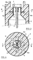
- la figure 1 est une vue en coupe longitudinale d'une installation suivant l'invention ;
- la figure 2 est une vue en coupe suivant le plan II-II de la figure 1 ;
- la figure 3 est une vue en coupe longitudinale partielle à échelle agrandie montrant la fixation de l'embase du compteur à la matière thermiquement isolante suivant le plan III-III de la figure 4 ;
- la figure 4 est une vue en coupe suivant le plan IV-IV de la figure 3 ;
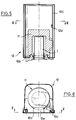
- la figure 5 est une vue en coupe longitudinale partielle à échelle agrandie de la cuve contenant le chapeau, suivant le plan V-V de la figure 6 ;
- la figure 6 est une vue en coupe suivant le plan VI-VI de la figure 5 ;
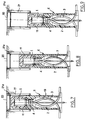
- la figure 7 est une vue schématique en coupe longitudinale d'une installation enterrée suivant l'invention ;
- les figures 8 et 9 sont des vues schématiques similaires à la figure 7.
- Figure 1 is a longitudinal sectional view of an installation according to the invention;
- Figure 2 is a sectional view along the plane II-II of Figure 1;
- Figure 3 is a partial longitudinal sectional view on an enlarged scale showing the attachment of the meter base to the thermally insulating material along the plane III-III of Figure 4;
- Figure 4 is a sectional view along the plane IV-IV of Figure 3;
- Figure 5 is a partial longitudinal sectional view on an enlarged scale of the tank containing the cap, along the plane VV of Figure 6;
- Figure 6 is a sectional view along the plane VI-VI of Figure 5;
- FIG. 7 is a schematic view in longitudinal section of a buried installation according to the invention;
- Figures 8 and 9 are schematic views similar to Figure 7.
Dans la réalisation des figures 1 à 4, l'installation de comptage d'eau comprend un compteur d'eau 1 relié à une conduite 2 d'arrivée d'eau et à une conduite 3 de départ d'eau, par exemple en polyéthylène. Le compteur d'eau 1 est monté sur une embase 4 dans laquelle débouchent lesdites conduites 2, 3 d'arrivée et de départ d'eau.In the embodiment of FIGS. 1 to 4, the water metering installation comprises a
Ces conduites 2, 3 s'étendent dans une tranchée réalisée dans le sol et pénètrent dans le sol au fond 5 de cette tranchée.These
Suivant l'invention, l'installation comprend une enveloppe 6 en matière thermiquement isolante formant le pied de l'installation qui entoure les conduites 2, 3 et est ouverte vers le bas. La partie supérieure 7 de cette enveloppe 6 comporte un passage vertical 8 dans lequel est engagée l'embase 4 du compteur. Cette embase 4 est fixée directement à la matière isolante de l'enveloppe 6 par des moyens qui seront détaillés plus loin évitant la création d'un pont thermique entre l'embase 4 et l'extérieur. L'épaisseur de matière isolante qui entoure l'embase 4 est supérieure à l'épaisseur de matière isolante gui entoure les conduites 2 et 3.According to the invention, the installation comprises an
De plus, l'épaisseur de matière isolante qui entoure les moyens de fixation de l'embase 4 dans la matière isolante est au moins égale à l'épaisseur de matière isolante qui entoure les conduites 2 et 3.In addition, the thickness of insulating material which surrounds the means for fixing the
L'enveloppe 6 en matière thermiquement isolante comprend une coque extérieure 9 moulée en matière plastique rigide recouverte sur sa face intérieure d'une matière thermiquement isolante 10.The
Cette matière thermiquement isolante 10 est de préférence une matière plastique expansée, telle qu'une mousse de polyuréthane.This thermally insulating
Par ailleurs, le compteur 1 est coiffé par un chapeau 11 en matière thermiquement isolante de même nature que celle de l'enveloppe 6. Le bord inférieur de ce chapeau 11 est en contact avec la partie supérieure de la matière thermiquement isolante de l'enveloppe 6.Furthermore, the
Le chapeau isolant 11 est lui-même contenu à l'intérieur d'une cuve 12 en matière plastique dont le bord inférieur 12a est solidaire du bord supérieur de l'enveloppe isolante 6. Cette cuve 12 comporte une porte latérale 12b.The
Par ailleurs, l'espace d'air 13 entourant les conduites 2, 3 communique avec l'espace d'air 14 compris entre le chapeau isolant 11 et le compteur 1 par des passages d'air 15 ménagés dans la paroi supérieure 7 de l'enveloppe isolante 6.Furthermore, the
On voit également sur la figure 1 que les bords en contact du chapeau isolant 11 et de l'enveloppe isolante 6 présentent des épaulements complémentaires 16b emboîtés l'un dans l'autre.It can also be seen in FIG. 1 that the edges in contact with the
Dans l'exemple représenté, le compteur 1 est monté de façon rotative sur l'embase 4 entre une position d'ouverture et de fermeture de l'arrivée d'eau. Cette disposition est connue selon le brevet français 87 03453. Par conséquent, la liaison entre le chapeau isolant 11 et la partie supérieure de l'enveloppe isolante 6 est adaptée pour permettre une rotation du compteur 1 entre les deux positions précitées ainsi que pour permettre un démontage et un échange dudit compteur 1.In the example shown, the
Comme on le voit sur la figure 3, la fixation entre l'embase 4 et l'ouverture 8 ménagée à la partie supérieure 7 de l'enveloppe isolante 6 est assurée par des pattes métalliques 16a scellées dans la matière isolante 10 de cette enveloppe. Les extrémités de ces pattes 16a sont situées à une distance suffisante de la face extérieure de l'enveloppe 6 pour éviter la création de ponts thermiques entre l'embase 4 et l'extérieur.As seen in Figure 3, the attachment between the
L'embase 4 est réalisée en matériau métallique moulé, par exemple du laiton. L'embase comprend un tube annulaire central coopérant avec un caloduc 18 pour assurer un transfert thermique. Ledit tube est solidaire de deux cloisons verticales orientées suivant un diamètre et assurant la rigidité mécanique de l'embase.The
Perpendiculairement audit diamètre, sont prévus deux manchons cylindriques diamétralement opposés et permettant l'emmanchement des conduites 2 et 3.Perpendicular to said diameter, two cylindrical sleeves are provided which are diametrically opposite and which allow the fitting of
On voit également sur la figure 1 que la partie inférieure 9a de la coque extérieure rigide 9 est évasée vers le bas, pour améliorer l'ancrage de l'enveloppe 6 dans le sol.We also see in Figure 1 that the
Par ailleurs, le bord inférieur de ladite partie évasée 9a comporte deux ouvertures 17a, 17b diamétralement opposées pour le passage des conduites 2, 3 d'arrivée et de départ d'eau.Furthermore, the lower edge of said flared
Dans la réalisation représentée, l'enveloppe isolante 6 entoure également un caloduc 18 s'étendant verticalement entre l'embase 4 et le fond 5 de la tranchée creusée dans le sol. Ce caloduc 18 pénètre suivant une certaine profondeur dans le sol pour y prélever des calories et maintenir ainsi l'embase 4 et le compteur à une température qui minimise les risques de gel.In the embodiment shown, the insulating
Sur les figures 5 et 6, on voit que le chapeau 11 est conformé de façon à pouvoir pivoter autour d'un axe 12c, qui permet également l'ouverture et le pivotement de la porte 12b.In Figures 5 and 6, we see that the
La porte 12b s'ouvre et pivote à 180° autour de l'axe 12c.The
Des moyens pour retenir le chapeau 11 en position haute comprennent une lame métallique élastique 12d.Means for retaining the
Lorsqu'on déboîte le chapeau 11 en le soulevant au-dessus des conformations 16b, on peut le lever jusqu'à une position supérieure où il sera retenu par la lame flexible 12d.When the
Lorsqu'on veut abaisser le chapeau 11, on appuie sur la lame 12d de façon à permettre le coulissement et la descente du chapeau 11 le long de l'axe 12c.When the
Le mode opératoire est le suivant :
- l'opérateur ouvre la
porte 12b, après l'avoir déverrouillée, et la fait pivoter de 180° autour de l'axe 12c ; - l'opérateur soulève le chapeau 11 jusqu'à le maintenir en position haute par la lame 12d ;
- l'opérateur fait pivoter le chapeau de 180° autour de l'axe 12c et intervient sur le compteur ;
- l'opérateur effectue les opérations inverses dans l'ordre inverse pour refermer et verrouiller la porte.
- the operator opens the
door 12b, after having unlocked it, and rotates it 180 ° around theaxis 12c; - the operator raises the
cap 11 until it is held in the high position by theblade 12d; - the operator rotates the cap 180 ° around the
axis 12c and intervenes on the counter; - the operator performs the reverse operations in reverse order to close and lock the door.
La porte 12b comprend un moyen 12e coopérant avec le chapeau 11 pour assurer la bonne mise en place et l'emboîtement du chapeau 11 sur les conformations 16b lorsque la porte est refermée.The
Le moyen 12e comprend une nervure horizontale située juste au-dessus de la face supérieure du chapeau isolant 11 lorsque le chapeau est emboîté et la porte refermée.The
Si le chapeau 11 n'est pas correctement emboîté, la nervure 12e vient en appui sur le haut du chapeau 11 et empêche la fermeture de la porte 12b.If the
Dans la réalisation des figures 7 à 9, l'installation est complètement contenue dans un puits 19 ménagé dans le sol, dont la profondeur est variable.In the embodiment of FIGS. 7 to 9, the installation is completely contained in a well 19 made in the ground, the depth of which is variable.
Le puits 19 est fermé à sa partie supérieure par un tampon 20 permettant d'accéder au compteur 1. La partie supérieure du puits comprend une rehausse 21 en forme de manchon dont le bord supérieur 21a reçoit le tampon 20.The well 19 is closed at its upper part by a
La surface intérieure de la rehausse 21 est adaptée à la surface extérieure de l'enveloppe 6 formant pied pour permettre un coulissement relatif entre cette rehausse 21 et l'enveloppe 6. Il est ainsi possible, comme le montrent les figures 7, 8 et 9, d'implanter l'installation à des profondeurs variables sans avoir à modifier la longueur de l'enveloppe 6. Il suffit à cet effet que la longueur axiale de la rehausse corresponde au moins à la différence entre les profondeurs maximale et minimale du puits 19.The inner surface of the
Les effets techniques et les avantages de l'installation selon l'invention sont les suivants :The technical effects and the advantages of the installation according to the invention are as follows:
La matière isolante continue de l'enveloppe 6 délimite avec le chapeau isolant emboîté 11 un volume d'air sensiblement isotherme sans pont thermique qui protège du gel tout le circuit intérieur hydraulique de l'installation.The continuous insulating material of the
L'ouverture en partie basse de l'enveloppe 6 formant pied permet en effet l'échange avec le sol par convection d'air dans le volume intérieur au pied et avec le volume intérieur au chapeau par le passage 15 prévu à cet effet. La température dudit volume intérieur devient donc sensiblement égale à celle régnant à la profondeur d'enfouissement dans le sol, qui est constante et comprise en général entre 4°C et 12°C. Le caloduc 18 relié à l'embase 4 renforce cet effet de protection contre le gel, en effectuant un transfert thermique depuis une profondeur plus importante, donc à une température plus élevée.The opening in the lower part of the
On a ainsi protégé du gel tout le circuit hydraulique et on diminue de plus l'usure du compteur d'eau qui se trouve dans la réalisation selon l'invention à l'abri des chocs thermiques. La fiabilité de l'installation s'en trouve donc accrue.The entire hydraulic circuit was thus protected from freezing and the wear of the water meter which is in the embodiment according to the invention is further reduced, sheltered from thermal shocks. The reliability of the installation is therefore increased.
L'évasement vers le bas de l'enveloppe 6 assure la stabilité de l'installation dans le sol en procurant un bon appui au pied et en outre une meilleure résistance à l'arrachement.The flaring down of the
Du fait de son volume extérieur réduit, l'installation est très facile à mettre en place et l'importance du chantier est comparable à la mise en place de simples canalisations. Par ailleurs, la moindre quantité de matières mises en oeuvre dans ce volume réduit entraîne une économie sur les coûts de fabrication.Due to its reduced external volume, the installation is very easy to install and the importance of the site is comparable to the installation of simple pipes. In addition, the lower quantity of materials used in this reduced volume results in savings on manufacturing costs.
Ainsi, la mise en place de l'installation dans le sol comprend les étapes suivantes :
- on réalise une tranchée depuis la conduite principale jusqu'à l'abonné, de largeur nécessaire à l'implantation d'une canalisation,
- on fore un trou adéquat pour le logement du caloduc 18 à l'emplacement choisi pour l'installation,
- on dépose un lit de sable au fond de la tranchée,
- on place l'installation verticalement dans la tranchée en mettant le caloduc 18 en place dans son trou de logement,
- on raccorde la conduite de départ à la canalisation du réseau de distribution et la conduite d'arrivée à la canalisation du réseau abonné,
- on établit la circulation d'eau et on teste le fonctionnement du dispositif et l'étanchéité après raccordement,
- on referme la tranchée par remblayage au niveau désiré en maintenant l'installation dans la position désirée.
- a trench is made from the main pipe to the subscriber, of width necessary for the installation of a pipeline,
- a suitable hole is drilled for housing the
heat pipe 18 at the location chosen for the installation, - a sand bed is deposited at the bottom of the trench,
- the installation is placed vertically in the trench by putting the
heat pipe 18 in place in its housing hole, - the outgoing pipe is connected to the distribution network pipe and the incoming pipe to the subscriber network pipe,
- the water circulation is established and the operation of the device and the tightness are tested after connection,
- the trench is closed by backfilling to the desired level while maintaining the installation in the desired position.
Les effets techniques précités révèlent les avantages de l'invention par rapport aux dispositifs existants : l'installation assure une meilleure protection contre le gel, est plus économique à fabriquer, plus facile à installer, d'un volume plus réduit et donc plus légère à transporter.The aforementioned technical effects reveal the advantages of the invention compared to existing devices: the installation provides better protection against frost, is more economical to manufacture, easier to install, of a smaller volume and therefore lighter to carry.
Bien entendu, l'invention n'est pas limitée aux modes de réalisation décrits ci-dessus et on peut y apporter des variantes d'exécution.Of course, the invention is not limited to the embodiments described above and it is possible to make variant embodiments.
On peut notamment disposer en fond de tranchée une grille à mailles fines pour assurer la propreté de l'espace 13 intérieur à l'enveloppe et empêcher la pénétration des insectes ou petits animaux. Cette grille est de préférence solidaire de l'installation et montée en usine.One can in particular have at the bottom of the trench a fine mesh grid to ensure the cleanliness of the
Claims (13)
Applications Claiming Priority (2)
| Application Number | Priority Date | Filing Date | Title |
|---|---|---|---|
| FR9013542A FR2668594B1 (en) | 1990-10-31 | 1990-10-31 | WATER PROTECTION AGAINST FREEZING. |
| FR9013542 | 1990-10-31 |
Publications (2)
| Publication Number | Publication Date |
|---|---|
| EP0484193A1 true EP0484193A1 (en) | 1992-05-06 |
| EP0484193B1 EP0484193B1 (en) | 1995-02-22 |
Family
ID=9401756
Family Applications (1)
| Application Number | Title | Priority Date | Filing Date |
|---|---|---|---|
| EP91402720A Expired - Lifetime EP0484193B1 (en) | 1990-10-31 | 1991-10-11 | Water meter installation protected against frost |
Country Status (7)
| Country | Link |
|---|---|
| EP (1) | EP0484193B1 (en) |
| AT (1) | ATE118877T1 (en) |
| CA (1) | CA2054538A1 (en) |
| DE (2) | DE484193T1 (en) |
| ES (1) | ES2033593T3 (en) |
| FR (1) | FR2668594B1 (en) |
| GR (1) | GR920300105T1 (en) |
Cited By (3)
| Publication number | Priority date | Publication date | Assignee | Title |
|---|---|---|---|---|
| EP1260799A1 (en) * | 2001-05-23 | 2002-11-27 | Atherm | Defrosting device for water meters using a heat pipe |
| GB2482060A (en) * | 2010-07-13 | 2012-01-18 | John Anthony O'brien | A thermal insulation cover for protecting a stopcock from freezing in the winter |
| CN108894281A (en) * | 2017-12-19 | 2018-11-27 | 上海熊猫机械(集团)有限公司 | A kind of integrated pumping plant of lower Inlet and outlet water anti-freeze type wisdom |
Families Citing this family (1)
| Publication number | Priority date | Publication date | Assignee | Title |
|---|---|---|---|---|
| DE102017005012A1 (en) * | 2017-05-24 | 2018-11-29 | Linde Aktiengesellschaft | Einfriersicherung |
Citations (2)
| Publication number | Priority date | Publication date | Assignee | Title |
|---|---|---|---|---|
| FR2499293A1 (en) * | 1981-02-02 | 1982-08-06 | Seperef | Buried enclosure for protection of flow counter - comprises moulded plastic box with tubular columns protruding into ground for heat extraction |
| FR2606052A1 (en) * | 1986-10-31 | 1988-05-06 | Cahors App Elec | Device for supporting and protecting a water meter against frost and its method of installation |
-
1990
- 1990-10-31 FR FR9013542A patent/FR2668594B1/en not_active Expired - Fee Related
-
1991
- 1991-10-11 AT AT91402720T patent/ATE118877T1/en not_active IP Right Cessation
- 1991-10-11 DE DE199191402720T patent/DE484193T1/en active Pending
- 1991-10-11 DE DE69107573T patent/DE69107573T2/en not_active Expired - Fee Related
- 1991-10-11 ES ES91402720T patent/ES2033593T3/en not_active Expired - Lifetime
- 1991-10-11 EP EP91402720A patent/EP0484193B1/en not_active Expired - Lifetime
- 1991-10-30 CA CA002054538A patent/CA2054538A1/en not_active Abandoned
-
1993
- 1993-02-17 GR GR920300105T patent/GR920300105T1/en unknown
Patent Citations (2)
| Publication number | Priority date | Publication date | Assignee | Title |
|---|---|---|---|---|
| FR2499293A1 (en) * | 1981-02-02 | 1982-08-06 | Seperef | Buried enclosure for protection of flow counter - comprises moulded plastic box with tubular columns protruding into ground for heat extraction |
| FR2606052A1 (en) * | 1986-10-31 | 1988-05-06 | Cahors App Elec | Device for supporting and protecting a water meter against frost and its method of installation |
Cited By (5)
| Publication number | Priority date | Publication date | Assignee | Title |
|---|---|---|---|---|
| EP1260799A1 (en) * | 2001-05-23 | 2002-11-27 | Atherm | Defrosting device for water meters using a heat pipe |
| FR2825148A1 (en) * | 2001-05-23 | 2002-11-29 | Atherm | DEVICE FOR FREEZING WATER METERS BY HEAT PIPE |
| GB2482060A (en) * | 2010-07-13 | 2012-01-18 | John Anthony O'brien | A thermal insulation cover for protecting a stopcock from freezing in the winter |
| GB2482060B (en) * | 2010-07-13 | 2015-08-26 | John Anthony O'brien | An insulating device |
| CN108894281A (en) * | 2017-12-19 | 2018-11-27 | 上海熊猫机械(集团)有限公司 | A kind of integrated pumping plant of lower Inlet and outlet water anti-freeze type wisdom |
Also Published As
| Publication number | Publication date |
|---|---|
| CA2054538A1 (en) | 1992-05-01 |
| ES2033593T3 (en) | 1995-05-01 |
| DE69107573T2 (en) | 1995-08-03 |
| DE484193T1 (en) | 1992-11-26 |
| ES2033593T1 (en) | 1993-04-01 |
| FR2668594B1 (en) | 1993-02-12 |
| ATE118877T1 (en) | 1995-03-15 |
| GR920300105T1 (en) | 1993-02-17 |
| DE69107573D1 (en) | 1995-03-30 |
| EP0484193B1 (en) | 1995-02-22 |
| FR2668594A1 (en) | 1992-04-30 |
Similar Documents
| Publication | Publication Date | Title |
|---|---|---|
| CA1239849A (en) | Protection device against freeze-up of storing or routing installations for freezable liquids, especially water | |
| EP0894430B1 (en) | Non-freezing drinker with constant liquid level for outside use. | |
| EP0484193B1 (en) | Water meter installation protected against frost | |
| EP0287407B1 (en) | Connecting and supporting apparatus for a water meter | |
| BE1016948A6 (en) | Trap of court (sterfput). | |
| FR2606052A1 (en) | Device for supporting and protecting a water meter against frost and its method of installation | |
| FR2483980A1 (en) | METHOD FOR BUILDING A HOUSE AND HOUSE RELATING THERETO | |
| KR101942403B1 (en) | Nonfreezing hydrant device with easy maintenance function | |
| FR2693320A1 (en) | Watertight pavement disconnecting box for underground service cable - has cylindrical body, with inner, sealed, and outer, load-bearing, covers, fused links and sealable cable entries | |
| CA1145572A (en) | Removable gutter for manholes and ducts | |
| EP3815523B1 (en) | Drinking trough for animals | |
| FR2627664A1 (en) | Livestock drinker unit - has conical bowl on top of hollow cylindrical support with inner layer on insulating material | |
| FR3060621A1 (en) | REGARDING AVALER WITH A COUPLED TUBE | |
| FR2490449A1 (en) | Modular construction for producing methane from organic waste - with identical walls and bases for digester(s), gas-holder(s) and plant room | |
| FR2678969A1 (en) | Device for protecting a waste-water discharge (soil) pipe of a dwelling from penetration by sewer rats | |
| FR2601847A1 (en) | Device for dispensing warm water for pigs | |
| EP0927847A1 (en) | Vent for an underground housing | |
| CH658279A5 (en) | Odour-seal device for a pipeline manhole | |
| FR2888592A1 (en) | OUTER TERMINAL HAVING A COUNTER ASSEMBLY | |
| FR2548544A1 (en) | Hydrant with non-return valve | |
| FR2732380A1 (en) | METHOD AND DEVICE FOR MAINTAINING AN EVACUATION DRAINAGE DURING A PIPELINE CONSTRUCTION | |
| WO2008145887A2 (en) | Snow coverage installation and housing for such an installation | |
| FR2719613A1 (en) | Prefabricated water meter installation for connection to public water supply | |
| FR2696808A1 (en) | Pipe connection device. | |
| FR2789098A1 (en) | Manhole for domestic gas supply pipe access has lid for shaft with valve chest in base having rain drain |
Legal Events
| Date | Code | Title | Description |
|---|---|---|---|
| PUAI | Public reference made under article 153(3) epc to a published international application that has entered the european phase |
Free format text: ORIGINAL CODE: 0009012 |
|
| 17P | Request for examination filed |
Effective date: 19911019 |
|
| AK | Designated contracting states |
Kind code of ref document: A1 Designated state(s): AT BE CH DE DK ES FR GB GR IT LI LU NL SE |
|
| GBC | Gb: translation of claims filed (gb section 78(7)/1977) | ||
| ITCL | It: translation for ep claims filed |
Representative=s name: BARZANO' E ZANARDO ROMA S.P.A. |
|
| TCNL | Nl: translation of patent claims filed | ||
| TCAT | At: translation of patent claims filed | ||
| DET | De: translation of patent claims | ||
| 17Q | First examination report despatched |
Effective date: 19940309 |
|
| GRAA | (expected) grant |
Free format text: ORIGINAL CODE: 0009210 |
|
| AK | Designated contracting states |
Kind code of ref document: B1 Designated state(s): AT BE CH DE DK ES FR GB GR IT LI LU NL SE |
|
| PG25 | Lapsed in a contracting state [announced via postgrant information from national office to epo] |
Ref country code: NL Free format text: LAPSE BECAUSE OF NON-PAYMENT OF DUE FEES Effective date: 19950222 Ref country code: GR Free format text: LAPSE BECAUSE OF FAILURE TO SUBMIT A TRANSLATION OF THE DESCRIPTION OR TO PAY THE FEE WITHIN THE PRESCRIBED TIME-LIMIT Effective date: 19950222 Ref country code: DK Effective date: 19950222 |
|
| REF | Corresponds to: |
Ref document number: 118877 Country of ref document: AT Date of ref document: 19950315 Kind code of ref document: T |
|
| REF | Corresponds to: |
Ref document number: 69107573 Country of ref document: DE Date of ref document: 19950330 |
|
| ITF | It: translation for a ep patent filed |
Owner name: BARZANO' E ZANARDO ROMA S.P.A. |
|
| REG | Reference to a national code |
Ref country code: ES Ref legal event code: FG2A Ref document number: 2033593 Country of ref document: ES Kind code of ref document: T3 |
|
| GBT | Gb: translation of ep patent filed (gb section 77(6)(a)/1977) |
Effective date: 19950413 |
|
| PG25 | Lapsed in a contracting state [announced via postgrant information from national office to epo] |
Ref country code: SE Effective date: 19950522 |
|
| NLV1 | Nl: lapsed or annulled due to failure to fulfill the requirements of art. 29p and 29m of the patents act | ||
| PG25 | Lapsed in a contracting state [announced via postgrant information from national office to epo] |
Ref country code: LU Free format text: LAPSE BECAUSE OF NON-PAYMENT OF DUE FEES Effective date: 19951031 |
|
| PLBE | No opposition filed within time limit |
Free format text: ORIGINAL CODE: 0009261 |
|
| STAA | Information on the status of an ep patent application or granted ep patent |
Free format text: STATUS: NO OPPOSITION FILED WITHIN TIME LIMIT |
|
| 26N | No opposition filed | ||
| REG | Reference to a national code |
Ref country code: CH Ref legal event code: NV Representative=s name: BOVARD AG PATENTANWAELTE |
|
| REG | Reference to a national code |
Ref country code: GB Ref legal event code: IF02 |
|
| PGFP | Annual fee paid to national office [announced via postgrant information from national office to epo] |
Ref country code: ES Payment date: 20041116 Year of fee payment: 14 |
|
| PGFP | Annual fee paid to national office [announced via postgrant information from national office to epo] |
Ref country code: BE Payment date: 20050415 Year of fee payment: 14 |
|
| PG25 | Lapsed in a contracting state [announced via postgrant information from national office to epo] |
Ref country code: ES Free format text: LAPSE BECAUSE OF NON-PAYMENT OF DUE FEES Effective date: 20051013 |
|
| PG25 | Lapsed in a contracting state [announced via postgrant information from national office to epo] |
Ref country code: BE Free format text: LAPSE BECAUSE OF NON-PAYMENT OF DUE FEES Effective date: 20051031 |
|
| REG | Reference to a national code |
Ref country code: FR Ref legal event code: TP |
|
| REG | Reference to a national code |
Ref country code: GB Ref legal event code: 732E |
|
| REG | Reference to a national code |
Ref country code: CH Ref legal event code: PUE Owner name: MANUFACTURE D'APPAREILLAGE ELECTRIQUE DE CAHORS S Free format text: MANUFACTURE D'APPAREILLAGE ELECTRIQUE DE CAHORS#BOITE POSTALE 149#CAHORS (FR) -TRANSFER TO- MANUFACTURE D'APPAREILLAGE ELECTRIQUE DE CAHORS SOCIETE PAR ACTIONS SIMPLIFIEE#ZONE INDUSTRIELLE DE REGOURD#46000 CAHORS (FR) |
|
| PGFP | Annual fee paid to national office [announced via postgrant information from national office to epo] |
Ref country code: GB Payment date: 20061011 Year of fee payment: 16 Ref country code: AT Payment date: 20061011 Year of fee payment: 16 |
|
| PGFP | Annual fee paid to national office [announced via postgrant information from national office to epo] |
Ref country code: IT Payment date: 20061031 Year of fee payment: 16 |
|
| REG | Reference to a national code |
Ref country code: ES Ref legal event code: FD2A Effective date: 20051013 |
|
| BERE | Be: lapsed |
Owner name: *MANUFACTURE D'APPAREILLAGE ELECTRIQUE DE CAHORS Effective date: 20051031 |
|
| PGFP | Annual fee paid to national office [announced via postgrant information from national office to epo] |
Ref country code: DE Payment date: 20071004 Year of fee payment: 17 |
|
| PGFP | Annual fee paid to national office [announced via postgrant information from national office to epo] |
Ref country code: CH Payment date: 20071029 Year of fee payment: 17 |
|
| GBPC | Gb: european patent ceased through non-payment of renewal fee |
Effective date: 20071011 |
|
| PG25 | Lapsed in a contracting state [announced via postgrant information from national office to epo] |
Ref country code: AT Free format text: LAPSE BECAUSE OF NON-PAYMENT OF DUE FEES Effective date: 20071011 |
|
| PG25 | Lapsed in a contracting state [announced via postgrant information from national office to epo] |
Ref country code: GB Free format text: LAPSE BECAUSE OF NON-PAYMENT OF DUE FEES Effective date: 20071011 |
|
| REG | Reference to a national code |
Ref country code: CH Ref legal event code: PL |
|
| PG25 | Lapsed in a contracting state [announced via postgrant information from national office to epo] |
Ref country code: DE Free format text: LAPSE BECAUSE OF NON-PAYMENT OF DUE FEES Effective date: 20090501 Ref country code: IT Free format text: LAPSE BECAUSE OF NON-PAYMENT OF DUE FEES Effective date: 20071011 |
|
| PG25 | Lapsed in a contracting state [announced via postgrant information from national office to epo] |
Ref country code: CH Free format text: LAPSE BECAUSE OF NON-PAYMENT OF DUE FEES Effective date: 20081031 Ref country code: LI Free format text: LAPSE BECAUSE OF NON-PAYMENT OF DUE FEES Effective date: 20081031 |
|
| PGFP | Annual fee paid to national office [announced via postgrant information from national office to epo] |
Ref country code: FR Payment date: 20091113 Year of fee payment: 19 |
|
| PG25 | Lapsed in a contracting state [announced via postgrant information from national office to epo] |
Ref country code: FR Free format text: LAPSE BECAUSE OF NON-PAYMENT OF DUE FEES Effective date: 20101102 |
|
| REG | Reference to a national code |
Ref country code: FR Ref legal event code: ST Effective date: 20110630 |