EP0484155B1 - Dispositif pour cintrer les tubes à poulies en tandem - Google Patents
Dispositif pour cintrer les tubes à poulies en tandem Download PDFInfo
- Publication number
- EP0484155B1 EP0484155B1 EP91310063A EP91310063A EP0484155B1 EP 0484155 B1 EP0484155 B1 EP 0484155B1 EP 91310063 A EP91310063 A EP 91310063A EP 91310063 A EP91310063 A EP 91310063A EP 0484155 B1 EP0484155 B1 EP 0484155B1
- Authority
- EP
- European Patent Office
- Prior art keywords
- bending
- pipe
- former
- axis
- arm
- Prior art date
- Legal status (The legal status is an assumption and is not a legal conclusion. Google has not performed a legal analysis and makes no representation as to the accuracy of the status listed.)
- Expired - Lifetime
Links
Images


Classifications
-
- B—PERFORMING OPERATIONS; TRANSPORTING
- B21—MECHANICAL METAL-WORKING WITHOUT ESSENTIALLY REMOVING MATERIAL; PUNCHING METAL
- B21D—WORKING OR PROCESSING OF SHEET METAL OR METAL TUBES, RODS OR PROFILES WITHOUT ESSENTIALLY REMOVING MATERIAL; PUNCHING METAL
- B21D7/00—Bending rods, profiles, or tubes
- B21D7/02—Bending rods, profiles, or tubes over a stationary forming member; by use of a swinging forming member or abutment
- B21D7/024—Bending rods, profiles, or tubes over a stationary forming member; by use of a swinging forming member or abutment by a swinging forming member
-
- B—PERFORMING OPERATIONS; TRANSPORTING
- B21—MECHANICAL METAL-WORKING WITHOUT ESSENTIALLY REMOVING MATERIAL; PUNCHING METAL
- B21D—WORKING OR PROCESSING OF SHEET METAL OR METAL TUBES, RODS OR PROFILES WITHOUT ESSENTIALLY REMOVING MATERIAL; PUNCHING METAL
- B21D7/00—Bending rods, profiles, or tubes
- B21D7/06—Bending rods, profiles, or tubes in press brakes or between rams and anvils or abutments; Pliers with forming dies
- B21D7/063—Pliers with forming dies
Definitions
- the invention pertains to pipe bending and more particularly to an apparatus and method for bending pipe using at least two means for exerting pressure against an inside former.
- Severe kinking is usually experienced with C350 grade pipe in conventional formers with a radius of bend of approximately three times the diameter of the pipe. There have been attempts to avoid this by increasing the former radius from three diameters to four diameters and by making the former tighter on the pipe, even to the point of having the pipe squeeze into the former. It is intended that this grip in the former will stop the pipe rising out of the former at the point of bend and allow a kink to form. These measures are successful on some types of pipe and in most cases kinking is not found while flattening and wrinkling are only minor.
- draw benders Certain more effective and also more complex and expensive benders are referred to as draw benders. They are arranged to start the bend at a predetermined point and progressively bend this section around a former in one direction only. This is usually done by providing a fixed inside former, with one reaction point also fixed. Bending is achieved by a sliding or rolling outside former following an arc concentric with the inside former's shape. This allows the reaction point to be kept relatively close to the actual point of bend at all times and high former contact pressure is maintained. This tends to minimise wrinkling. However, with some extra light wall sections, wrinkling is still encountered with considerably flattening around the outside of the bend.
- Draw benders are usually arranged to make a bend progressively in one direction from a start point, by engaging the pipe to be bent between a fixed reaction point, a fixed inside former and a movable outside member which is attached pivotally at the centre of the fixed former.
- Some variations use a fixed outside member and an inside former and clamping reaction member that rotate together pulling the pipe around the bend.
- a pipe bender comprising a base, a former mounted on the base and having a former surface extending angularly at a fixed radius about a bending axis, said former surface being provided to engage a length of pipe to be bent to conform to at least a portion of the length of said former surface; a bending arm pivotally mounted on said base for pivotting movement about said axis; a bending assembly mounted on said arm, said assembly includes two deforming rollers rotatably mounted for movement about an axes parallel to said bending axis, and spaced radially outwardly of said surface, said rollers being adapted to engage said length of pipe to cause bending thereof as it is moved angularly about said axis; said roller being substantially co-extensive with one roller being positioned radi
- the two rollers are mounted for movement at constant radii, the leading roller having a larger radius.
- the two deforming rollers are rotatably mounted on a flange which is pivotally supported by said bending arm.
- a conventional fixed post bender 10 uses a rigid, curved former 11 which controls both the cross-sectional profile of the section and the radius of the bend. Fixed posts 12 are set apart while the former 11 is forced into the section between the posts to create the bend.
- Fig. 2 Illustrates a variant of a conventional fixed post bender which allows the reaction points 13 to be kept fairly close to the point of the bend while also allowing them to move outwards (in the direction of the arrows 14) as bending progresses. This is done by mounting rollers 15 on each of two pivotted arms 16.
- Fig. 3 illustrates a prior art induction bender 20. A fixed inside former 21 cooperates with a sliding or rolling outside former 22.
- leading outside former 57 applies the bending force as a moment and that the trailing outside former 58 applies a force to the material to contain and control the shape of material in the inside former 50. It is preferred that the trailing outside former 58 be located at or near the point of bend. The trailing outside former 58 need not be located precisely at the point of bend. In a preferred embodiment, a gap of several millimeters is left between the outside diameter of the trailing former end the outside diameter of the inside former. This ensures that the pressure exerted by the trailing edge former is also exerted onto the section or pipe being bent and not transmitted directly onto the inside former.
- the distance separating the two outside formers could vary greatly so that the contact they have with the material being bent could be very close or quite distant.
- the two outside formers while preferably mounted on a common pivotting carriage, could be moved into and out of position by separate means. Hydraulic, pneumatic, electrical, magnetic or mechanical devices can be used to move each outside former into and out of position independent of the other outside formers.
- the pivot point 56 of the carriage 55 can be moved relative to the rotational centres of the outside formers to as to vary the geometry and hence the contact pressure exerted by the trailing outside former 58.
- rollers and cradle 55 rotate with respect to the centre of the inside former or whether the former and section being bent rotate with respect to a fixed set of outside formers.
- rollers or other means for exerting pressure may be mounted on a rotating arm or urged into position in other suitable ways.
- two pairs of outside formers could be located to allow bending to proceed around the inside former in opposite directions and simultaneously.
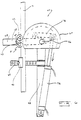
- Fig. 6 illustrates an example of a pipe bending apparatus 60 utilizing tandem rollers 61 as disclosed with reference to Fig. 5.
- the rollers 62 are mounted on a common cradle 63 which rotates about a pivot point 64.
- the cradle 63 pivots with respect to an arm 65 which rotates about the centre 66 of the inside former 67.
- a central post 68 to which the inside former is mounted also bears an arm 69 which provides a fixed reaction point 70 for the material which is being bent 71.
- a hydraulic cylinder 72 in combination with a link mechanism 73 allows the arm 65 to be rotated at least 180° with respect to the inside former. This particular arrangement for rotating the arm 65 is described more completely in Australian Patent Application No. 58906/90.
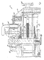
- FIG. 7 to 13 of the accompanying drawings there is schematically depicted a pipe bender 110.
- the bender 110 has a base 111 from which there extends legs 112 to support the base 111 on a ground surface.
- the base 111 is basically a hollow housing which pivotally supports an arm 113 for pivotting movement about a generally vertical axis defined by the main pin 114.
- a bending assembly 115 which includes a carriage 116.
- the carriage 116 is slidably mounted on the arm 113 for longitudinal movement relative thereto. This movement is effected by means of a threaded shaft 117 provided at its outer end with an adjustment wheel or lever 118.
- the shaft 117 threadably engages a threaded passage 119 formed in the arm 113.
- the bending assembly 115 further includes a roller support 120 pivotally mounted by means of a secondary pin 140.
- the support 120 co-operates with a pair of vertically spaced generally horizontal flanges 121 to support two or more rollers.
- two rollers 122 and 123 are provided.
- the flanges 121 are joined by means of a handle 124 which is pivotally supported by passing through a passage in the support 120.
- the rollers are each supported by means of a pin 125.
- the roller 122 is positioned at the point of bending and the roller 123 is positioned forward thereof.
- the roller 123 is located angularly forward of and radially further out than the roller 122, relative to the bending axis.
- a hydraulic ram 126 having a cylinder 127 pivotally mounted at one end by means of a pin 145.
- the ram 126 has a piston rod 129 terminating with a yolk 128.
- the yolk 128 is pivotally attached to a link 129 by means of a pin 130.
- the other end of the link 129 is pivotally attached to the arm 113 by means of a pin 131.
- the arm 113 is also provided with a socket 146 which receives the pin 130 during various phases of movement of the arm 113 about the pin 114.
- a former 132 which is provided with a former surface 133 which extends angularly about the pin 114, at a generally constant radius.
- the former surface 132 is concave in transverse cross-section.
- a length of pipe 134 to be deformed by the bender 110 is bended to generally conform to the surface 132 and therefore the pin 114 also defines the bending axis about which the pipe 134 is bent.
- the hydraulic ram 126 is controlled in its movement by means of a spool valve 135, operated by means of a lever 136 extending upwardly through the base 111.
- the spool valve 135 receives hydraulic fluid under pressure and delivers it to the cylinder 127.
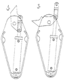
- hydraulic fluid under pressure is delivered to the cylinder 127 to cause the piston rod 129 to telescopically extend from within the cylinder 127.
- This telescopic movement commenced from when the hydraulic ram 126 is configured as shown in Figure 4.
- the arm 113 is caused to pivot due to engagement of the pin 130 with the socket 132. This continues until the arm 113 has reached the position depicted in Figure 6. At this position, the arm 113 pivots to remove the pin 130 from contact within the socket 146. However the arm 113 continues to pivot due to the force being applied to the arm 113 via the link 129.
- the spool valve 135 has a cam follower 136 which engages a cam 137 fixed to the arm 113 (via the pin 125) so as to rotate with the arm 113.
- the cam 137 Is adjustable to return the spool valve 135 to the start position and/or to cause the spool valve 135 to return the arm 113 to the start position. Accordingly, the cam 137 can be used to govern the angle through which the pipe 134 is bent.
- the former 132 is mounted on the pin 114 but is removable. This enables formers of various sizes to be used so that varying radii may be produced.
- the former 132 has a rear recess 139 which engages a projection 140 on the base 111, so that the former 132 is held stationary during operation.
- a pipe support 141 which engages the pipe 134 to retain one portion stationary with respect to the base 111 during bending.
- the bender 110 is described as bending in one predetermined direction. However it should be appreciated that bending can take place in the reverse direction. This is achieved by removing the former 132. Thereafter, the lever 136 is removed together with the cam 137 by release of the bolt 138. The handle 118 is then rotated to remove the bending assembly 115. Next the main pin 114 is removed which enables the arm 113 to be pulled from within the base 111. This is achieved by telescopic movement of the piston rod 127 outwardly with respect to the cylinder 127. Thereafter, the arm 113, link 129 and piston rod 127 are rotated about the axis of the piston rod 127, through 180°.
- the handle 118 is rotated in order to move the rollers 122 radially with respect to the pin 114, in order to accommodate pipes of different diameters. It should further be appreciated that two or more rollers 122 may be employed, with one of the rollers being positioned at the point of deformation of the pipe 134.
Landscapes
- Engineering & Computer Science (AREA)
- Mechanical Engineering (AREA)
- Bending Of Plates, Rods, And Pipes (AREA)
- Machines For Manufacturing Corrugated Board In Mechanical Paper-Making Processes (AREA)
Claims (10)
- Cintreuse de tubes comprenant une embase (111), un outil de formage (132) monté sur l'embase et comportant une face de formage (133) qui s'étend angulairement à un rayon fixe par rapport à l'axe de cintrage (114), cette face de formage devant porter sur une longueur de tube (134) à cintrer pour qu'elle prenne la forme de cette face de formage sur au moins une partie de sa longueur;
un bras de cintrage (113) monté sur cette embase et pouvant pivoter sur cette embase par rapport à l'axe de cintrage;
un ensemble de cintrage (115) monté sur ce bras de cintrage, cet ensemble conprenant deux galets de déformation (122, 123) rotatifs par rapport à des axes parallèles à cet axe de cintrage et distant radialement de cette face de formage vers l'extérieur, ces galets de déformation ayant été étudiés pour qu'ils appuient sur la longueur de tube à cintrer pour la cintrer au fur et à mesure qu'elle se déplace angulairement par rapport à l'axe de cintrage;
ces galets de déformation étant co-extensifs et l'un d'entre eux étant placé radialement par rapport à l'axe de cintrage de façon à ce que pendant le fonctionnement de la cintreuse ce galet de déformation soit placé approximativement au point de cintrage du tube, l'autre galet de déformation étant éloigné angulaire en avant de ce galet de déformation et à une distance plus grande radialement par rapport à l'axe de cintrage que le précédent galet de déformation; et
un moyen motorisé pour impartir un mouvement angulaire au bras de cintrage autour de l'axe de cintrage et pour déplacer de ce fait le galet de déformation pour déformer le tube à cintrer, cette cintreuse étant caractérisée par le fait que;
les deux galets de déformation sont montés sur une bride (121) et peuvent pivoter sur cette bride qui elle-même est supportée par le bras de cintrage par rapport auquel elle peut pivoter. - Cintreuse de tube selon la revendication 1 comprenant en outre un élément de réaction (141 monté sur l'embase et étudié pour s'appliquer sur la longueur de tube à cintrer pendant le cintrage de cette longueur de tube et maintenir une partie de cette longueur de tube à cintrer en contact avec la face de cintrage
- Cintreuse de tube selon la revendication 1 ou la revendication 2, dans laquelle le bras de cintrage comporte un moyen (116) permettant de sélectionner la position radiale de l'ensemble de cintrage par rapport à la surface de cintrage.
- Cintreuse de tube selon l'une quelconque des revendications qui précèdent, dans laquelle le moyen motorisé comprend un vérin hydraulique (127) dont une des extrémités est montée sur l'embase et peut pivoter par rapport à cette embase et dont l'autre extrémité est connecté au bras de cintrage par un dispositif pivotant.
- Cintreuse de tube selon la revendication 4, dans laquelle cette autre extrémité du vérin hydraulique est connectée par un pivot à une biellette (129) par l'intermédiaire d'un axe (130), cette biellette étant à son tour connectée par un pivot au bras de cintrage, et dans lequel vérin hydraulique l'axe (130) est étudié pour porter à l'intérieur d'un emboîtement (146) à l'extrémité du bras de cintrage (113) sur au moins une portion de la rotation de pivotement du bras de cintrage.
- Cintreuse de tube selon la revendication 4 ou la revendication 5 comprenant en outre une butée montée sur l'embase pour servir de moyen d'arrêt d'angle de pivotement du vérin hydraulique.
- Cintreuse de tube selon la revendication 5 ou la revendication 6, dans laquelle le bras de cintrage, la biellette et le vérin hydraulique peuvent tourner autour d'un axe du vérin hydraulique sur un angle de 180° pour permettre à la cintreuse de tube de fonctionner en direction opposée.
- Cintreuse de tube selon l'une quelconque des revendications ci-dessus comprenant une soupape à tiroir (135) ayant un suiveur de came (136) qui porte sur une came (137) fixée au bras de cintrage, cette came étant réglable pour la faire coopérer avec la soupape à tiroir pour contrôler l'angle de cintrage de la longueur de tube.
- Cintreuse de tube selon l'une quelconque des revendications ci-dessus dans laquelle l'outil de formage est amovible pour permettre l'utilisation d'outils de formage de différents rayons.
- Cintreuse de tube selon l'une quelconque des revendications précédentes dans laquelle l'outil de formage comprend une cavité étudiée pour permettre l'insertion d'une saillie (140) de l'embase, cette insertion de la saillie de l'embase à l'intérieur de la cavité permettant de maintenir l'outil de formage en position fixe par rapport à l'embase pendant le fonctionnement de la cintreuse.
Applications Claiming Priority (4)
| Application Number | Priority Date | Filing Date | Title |
|---|---|---|---|
| AUPK311090 | 1990-10-31 | ||
| AU3110/90 | 1990-10-31 | ||
| AU7805/91 | 1991-08-16 | ||
| AUPK780591 | 1991-08-16 |
Publications (3)
| Publication Number | Publication Date |
|---|---|
| EP0484155A2 EP0484155A2 (fr) | 1992-05-06 |
| EP0484155A3 EP0484155A3 (en) | 1992-07-29 |
| EP0484155B1 true EP0484155B1 (fr) | 1995-01-25 |
Family
ID=25643962
Family Applications (1)
| Application Number | Title | Priority Date | Filing Date |
|---|---|---|---|
| EP91310063A Expired - Lifetime EP0484155B1 (fr) | 1990-10-31 | 1991-10-31 | Dispositif pour cintrer les tubes à poulies en tandem |
Country Status (8)
| Country | Link |
|---|---|
| US (1) | US5390522A (fr) |
| EP (1) | EP0484155B1 (fr) |
| AT (1) | ATE117601T1 (fr) |
| BR (1) | BR9104750A (fr) |
| CA (1) | CA2054557A1 (fr) |
| DE (1) | DE69107016T2 (fr) |
| ES (1) | ES2070443T3 (fr) |
| NZ (1) | NZ240419A (fr) |
Families Citing this family (15)
| Publication number | Priority date | Publication date | Assignee | Title |
|---|---|---|---|---|
| AUPM279293A0 (en) * | 1993-12-03 | 1994-01-06 | Dircks, Robert Alexander | Pipe bending apparatus |
| US6097012A (en) * | 1998-01-14 | 2000-08-01 | Hajime Yoshida | Induction-heating bender |
| WO2008102477A1 (fr) * | 2007-02-21 | 2008-08-28 | Nippon Steel Corporation | Appareil et procédé pour cintrer à la presse un matériau tubulaire |
| ES2367489B1 (es) | 2008-04-04 | 2012-09-07 | Rothenberger, S.A. | Curvatubos de accionamiento manual. |
| US8234898B1 (en) | 2008-12-12 | 2012-08-07 | Wilson Brian S | Bending assembly for extruded stock material |
| US9283605B2 (en) | 2010-05-05 | 2016-03-15 | Greenlee Textron Inc. | Pivoting conduit bender |
| US9156075B2 (en) | 2013-01-25 | 2015-10-13 | Irwin Industrial Tool Company | Lever bender and related method of use |
| US9718108B2 (en) * | 2014-09-11 | 2017-08-01 | Huskie Tools, Inc. | Powered bending tool |
| US10537770B2 (en) * | 2015-12-27 | 2020-01-21 | Karsten Manufacturing Corporation | Golf club heads with stronger, more flexible, and lighter materials |
| JP7025955B2 (ja) * | 2018-02-22 | 2022-02-25 | 三桜工業株式会社 | 曲げ型へのチューブ自動嵌め込み装置 |
| US10702323B2 (en) * | 2018-03-29 | 2020-07-07 | Aesculap Ag | Spinal fixation rod bending instrument |
| CN111571223A (zh) * | 2020-04-25 | 2020-08-25 | 齐云龙 | 一种板材自动卷圆机 |
| CN113102577A (zh) * | 2021-04-01 | 2021-07-13 | 白红涛 | 一种笔记本电脑散热铜管成型装置 |
| CN113477763B (zh) * | 2021-07-27 | 2023-06-02 | 温州国乐不锈钢管业有限公司 | 一种不锈钢管自动弯管设备及弯管加工工艺 |
| CN113458202B (zh) * | 2021-08-05 | 2022-11-29 | 中国科学院合肥物质科学研究院 | 一种便于调节角度的弯管装置 |
Family Cites Families (16)
| Publication number | Priority date | Publication date | Assignee | Title |
|---|---|---|---|---|
| US2346371A (en) * | 1942-01-30 | 1944-04-11 | Trimble & Fink Mfg Company | Tube bender |
| US2620848A (en) * | 1949-08-08 | 1952-12-09 | Paoli Louis De | Pipe bender |
| US2656872A (en) * | 1950-03-23 | 1953-10-27 | Hossfeld Mfg Company | Iron bending machine |
| US2754880A (en) * | 1954-10-19 | 1956-07-17 | Tal Bender Inc | Combination pipe bending apparatus and auxiliary pivoted tube bender |
| US3236082A (en) * | 1961-07-24 | 1966-02-22 | Crawford Fitting Co | Tube bending tools |
| US3380283A (en) * | 1965-01-11 | 1968-04-30 | Parker Hannifin Corp | Tube bending tool |
| US3613430A (en) * | 1969-07-25 | 1971-10-19 | Silas R Crees | Wire bending apparatus |
| CH545143A (fr) * | 1971-11-25 | 1973-12-15 | Miescher Marcel | Appareil pour couder les tubes en métal tendre |
| GB1463522A (en) * | 1974-09-11 | 1977-02-02 | Russel Bowen Systems Ltd | Bending machines |
| US3949584A (en) * | 1974-12-23 | 1976-04-13 | Greenlee Bros. & Co. | Bending apparatus having a roller support unit for E.M.T., conduit and thin wall tubing |
| SE435025B (sv) * | 1976-05-06 | 1984-09-03 | Arenco Parts Ab | Anordning for bockning av ror till slingor med stigning |
| SU627885A1 (ru) * | 1977-05-24 | 1978-10-15 | Бийский Котельный Завод | Трубогибочный станок |
| US4180997A (en) * | 1978-04-17 | 1980-01-01 | Applied Power Inc. | Single piece self-supporting shoe for use in a conduit bender |
| SU884789A1 (ru) * | 1979-11-22 | 1981-11-30 | Всесоюзный Научно-Исследовательский Институт По Монтажным И Специальным Строительным Работам | Устройство дл гибки труб |
| US4546632A (en) * | 1982-04-14 | 1985-10-15 | Applied Power Inc. | Portable conduit bending apparatus |
| US4938050A (en) * | 1989-06-22 | 1990-07-03 | Usui Kokusai Sangyo Kaisha Ltd. | Small-diameter metallic conduit bending machine |
-
1991
- 1991-10-30 CA CA002054557A patent/CA2054557A1/fr not_active Abandoned
- 1991-10-31 EP EP91310063A patent/EP0484155B1/fr not_active Expired - Lifetime
- 1991-10-31 BR BR919104750A patent/BR9104750A/pt not_active Application Discontinuation
- 1991-10-31 ES ES91310063T patent/ES2070443T3/es not_active Expired - Lifetime
- 1991-10-31 DE DE69107016T patent/DE69107016T2/de not_active Expired - Fee Related
- 1991-10-31 NZ NZ240419A patent/NZ240419A/en unknown
- 1991-10-31 AT AT91310063T patent/ATE117601T1/de not_active IP Right Cessation
-
1993
- 1993-12-28 US US08/175,472 patent/US5390522A/en not_active Expired - Fee Related
Also Published As
| Publication number | Publication date |
|---|---|
| EP0484155A3 (en) | 1992-07-29 |
| ES2070443T3 (es) | 1995-06-01 |
| US5390522A (en) | 1995-02-21 |
| ATE117601T1 (de) | 1995-02-15 |
| BR9104750A (pt) | 1992-06-16 |
| EP0484155A2 (fr) | 1992-05-06 |
| DE69107016T2 (de) | 1995-10-12 |
| CA2054557A1 (fr) | 1992-05-01 |
| DE69107016D1 (de) | 1995-03-09 |
| NZ240419A (en) | 1994-05-26 |
Similar Documents
| Publication | Publication Date | Title |
|---|---|---|
| EP0484155B1 (fr) | Dispositif pour cintrer les tubes à poulies en tandem | |
| EP3225321B1 (fr) | Procédé de fabrication d'un tuyau en acier | |
| US6216511B1 (en) | Apparatus and method for smoothing a welded seam of steel pipe | |
| US4706488A (en) | Method of roll forming cylindrical pipe | |
| US4456036A (en) | Wire bending apparatus and a method of bending a wire | |
| US5499521A (en) | Tube bender apparatus | |
| US20030226387A1 (en) | Orbiting roller groover for pipe | |
| EP0733428B1 (fr) | Méthode et appareil pour couper et perforer des tubes | |
| JPS5910854B2 (ja) | シ−ム溶接された金属管を製造する方法 | |
| JPS6154487B2 (fr) | ||
| CN116372451A (zh) | 一种带有定位功能的焊管焊接设备 | |
| AU657705B2 (en) | Tandem roller pipe bender | |
| US7251976B2 (en) | Apparatus and method for the noncircular bending of tubes | |
| US6655182B2 (en) | Apparatus and method for reshaping tubes | |
| CN217941472U (zh) | 一种便于调节的无缝钢管用弯折装置 | |
| JP2927394B2 (ja) | 管の楕円矯正装置 | |
| JPH0429471B2 (fr) | ||
| CA2243702C (fr) | Procede et dispositif pour produire des tubes selon le procede uoe | |
| JPH0679356A (ja) | 直列ローラ式管曲げ機 | |
| JP3035025B2 (ja) | 型材曲げ機 | |
| IE49621B1 (en) | A process and machine for producing seamless pipe bends | |
| JPS6242715B2 (fr) | ||
| CN220717345U (zh) | 一种三辊弯管机 | |
| EP0626222A1 (fr) | Procédé et dispositif de formation d'un rebord rectangulaire au bout d'un tube | |
| CN217070475U (zh) | 一种螺旋管扩口装置 |
Legal Events
| Date | Code | Title | Description |
|---|---|---|---|
| PUAI | Public reference made under article 153(3) epc to a published international application that has entered the european phase |
Free format text: ORIGINAL CODE: 0009012 |
|
| AK | Designated contracting states |
Kind code of ref document: A2 Designated state(s): AT BE CH DE DK ES FR GB GR IT LI LU NL SE |
|
| PUAL | Search report despatched |
Free format text: ORIGINAL CODE: 0009013 |
|
| AK | Designated contracting states |
Kind code of ref document: A3 Designated state(s): AT BE CH DE DK ES FR GB GR IT LI LU NL SE |
|
| 17P | Request for examination filed |
Effective date: 19930129 |
|
| 17Q | First examination report despatched |
Effective date: 19930805 |
|
| GRAA | (expected) grant |
Free format text: ORIGINAL CODE: 0009210 |
|
| AK | Designated contracting states |
Kind code of ref document: B1 Designated state(s): AT BE CH DE DK ES FR GB GR IT LI LU NL SE |
|
| PG25 | Lapsed in a contracting state [announced via postgrant information from national office to epo] |
Ref country code: NL Effective date: 19950125 Ref country code: LI Effective date: 19950125 Ref country code: GR Free format text: LAPSE BECAUSE OF FAILURE TO SUBMIT A TRANSLATION OF THE DESCRIPTION OR TO PAY THE FEE WITHIN THE PRESCRIBED TIME-LIMIT Effective date: 19950125 Ref country code: DK Effective date: 19950125 Ref country code: CH Effective date: 19950125 Ref country code: BE Effective date: 19950125 Ref country code: AT Effective date: 19950125 |
|
| REF | Corresponds to: |
Ref document number: 117601 Country of ref document: AT Date of ref document: 19950215 Kind code of ref document: T |
|
| REF | Corresponds to: |
Ref document number: 69107016 Country of ref document: DE Date of ref document: 19950309 |
|
| ITF | It: translation for a ep patent filed |
Owner name: FIAMMENGHI - DOMENIGHETTI |
|
| PG25 | Lapsed in a contracting state [announced via postgrant information from national office to epo] |
Ref country code: SE Effective date: 19950425 |
|
| REG | Reference to a national code |
Ref country code: CH Ref legal event code: PL |
|
| REG | Reference to a national code |
Ref country code: ES Ref legal event code: FG2A Ref document number: 2070443 Country of ref document: ES Kind code of ref document: T3 |
|
| ET | Fr: translation filed | ||
| NLV1 | Nl: lapsed or annulled due to failure to fulfill the requirements of art. 29p and 29m of the patents act | ||
| PG25 | Lapsed in a contracting state [announced via postgrant information from national office to epo] |
Ref country code: LU Free format text: LAPSE BECAUSE OF NON-PAYMENT OF DUE FEES Effective date: 19951031 |
|
| PLBE | No opposition filed within time limit |
Free format text: ORIGINAL CODE: 0009261 |
|
| STAA | Information on the status of an ep patent application or granted ep patent |
Free format text: STATUS: NO OPPOSITION FILED WITHIN TIME LIMIT |
|
| 26N | No opposition filed | ||
| PGFP | Annual fee paid to national office [announced via postgrant information from national office to epo] |
Ref country code: GB Payment date: 19961029 Year of fee payment: 6 Ref country code: FR Payment date: 19961029 Year of fee payment: 6 |
|
| PGFP | Annual fee paid to national office [announced via postgrant information from national office to epo] |
Ref country code: ES Payment date: 19961030 Year of fee payment: 6 |
|
| PG25 | Lapsed in a contracting state [announced via postgrant information from national office to epo] |
Ref country code: GB Free format text: LAPSE BECAUSE OF NON-PAYMENT OF DUE FEES Effective date: 19971031 Ref country code: FR Free format text: THE PATENT HAS BEEN ANNULLED BY A DECISION OF A NATIONAL AUTHORITY Effective date: 19971031 |
|
| PG25 | Lapsed in a contracting state [announced via postgrant information from national office to epo] |
Ref country code: ES Free format text: LAPSE BECAUSE OF NON-PAYMENT OF DUE FEES Effective date: 19971101 |
|
| GBPC | Gb: european patent ceased through non-payment of renewal fee |
Effective date: 19971031 |
|
| REG | Reference to a national code |
Ref country code: FR Ref legal event code: ST |
|
| PGFP | Annual fee paid to national office [announced via postgrant information from national office to epo] |
Ref country code: DE Payment date: 20010626 Year of fee payment: 10 |
|
| PG25 | Lapsed in a contracting state [announced via postgrant information from national office to epo] |
Ref country code: DE Free format text: LAPSE BECAUSE OF NON-PAYMENT OF DUE FEES Effective date: 20020702 |
|
| REG | Reference to a national code |
Ref country code: ES Ref legal event code: FD2A Effective date: 19981113 |
|
| PG25 | Lapsed in a contracting state [announced via postgrant information from national office to epo] |
Ref country code: IT Free format text: LAPSE BECAUSE OF NON-PAYMENT OF DUE FEES;WARNING: LAPSES OF ITALIAN PATENTS WITH EFFECTIVE DATE BEFORE 2007 MAY HAVE OCCURRED AT ANY TIME BEFORE 2007. THE CORRECT EFFECTIVE DATE MAY BE DIFFERENT FROM THE ONE RECORDED. Effective date: 20051031 |