EP0484004A1 - Echangeur de chaleur - Google Patents
Echangeur de chaleur Download PDFInfo
- Publication number
- EP0484004A1 EP0484004A1 EP91309535A EP91309535A EP0484004A1 EP 0484004 A1 EP0484004 A1 EP 0484004A1 EP 91309535 A EP91309535 A EP 91309535A EP 91309535 A EP91309535 A EP 91309535A EP 0484004 A1 EP0484004 A1 EP 0484004A1
- Authority
- EP
- European Patent Office
- Prior art keywords
- header
- heat exchanger
- fastener
- exchanger according
- embracing
- Prior art date
- Legal status (The legal status is an assumption and is not a legal conclusion. Google has not performed a legal analysis and makes no representation as to the accuracy of the status listed.)
- Granted
Links
Images


Classifications
-
- B—PERFORMING OPERATIONS; TRANSPORTING
- B23—MACHINE TOOLS; METAL-WORKING NOT OTHERWISE PROVIDED FOR
- B23K—SOLDERING OR UNSOLDERING; WELDING; CLADDING OR PLATING BY SOLDERING OR WELDING; CUTTING BY APPLYING HEAT LOCALLY, e.g. FLAME CUTTING; WORKING BY LASER BEAM
- B23K1/00—Soldering, e.g. brazing, or unsoldering
- B23K1/0008—Soldering, e.g. brazing, or unsoldering specially adapted for particular articles or work
- B23K1/0012—Brazing heat exchangers
-
- F—MECHANICAL ENGINEERING; LIGHTING; HEATING; WEAPONS; BLASTING
- F28—HEAT EXCHANGE IN GENERAL
- F28F—DETAILS OF HEAT-EXCHANGE AND HEAT-TRANSFER APPARATUS, OF GENERAL APPLICATION
- F28F9/00—Casings; Header boxes; Auxiliary supports for elements; Auxiliary members within casings
- F28F9/001—Casings in the form of plate-like arrangements; Frames enclosing a heat exchange core
- F28F9/002—Casings in the form of plate-like arrangements; Frames enclosing a heat exchange core with fastening means for other structures
-
- F—MECHANICAL ENGINEERING; LIGHTING; HEATING; WEAPONS; BLASTING
- F28—HEAT EXCHANGE IN GENERAL
- F28F—DETAILS OF HEAT-EXCHANGE AND HEAT-TRANSFER APPARATUS, OF GENERAL APPLICATION
- F28F2275/00—Fastening; Joining
- F28F2275/04—Fastening; Joining by brazing
-
- F—MECHANICAL ENGINEERING; LIGHTING; HEATING; WEAPONS; BLASTING
- F28—HEAT EXCHANGE IN GENERAL
- F28F—DETAILS OF HEAT-EXCHANGE AND HEAT-TRANSFER APPARATUS, OF GENERAL APPLICATION
- F28F2275/00—Fastening; Joining
- F28F2275/14—Fastening; Joining by using form fitting connection, e.g. with tongue and groove
Definitions
- the invention relates to a heat exchanger for use as a condenser in the automobile air conditioner or room air conditioner system, as an evaporator, oil cooler or the like.
- the so-called multi-flow type of heat exchanger is known and used as the condenser in the automobile air conditioner system.
- This heat exchanger comprises a plurality of flat tubes disposed in parallel with each other, and a plurality of fin members each interposed between two adjacent tubes, wherein both ends of each tube are connected to hollow cylindrical headers in fluid communication therewith.
- the headers of those heat exchangers comprise certain fasteners which are used for example to mount said heat exchangers as the condensers of air conditioner on the car bodies, or otherwise to connect some accessories to the heat exchangers. It has been a common practice to temporarily fix the fasteners on outer peripheries of the headers at desirable portions thereof. The fastners have been brazed, in an oven, to the headers so as to become integral with them.
- the present invention aims to provide a heat exchanger which does not need any special attachment to temporarily fix fasteners on headers of the heat exchanger, thereby improving the manufacture productivity thereof.
- a fastener as one constituent of a heat exchanger provided in the present invention comprises at least one embracing portions capable of being forced to fit on a header, when the fastener is urged towards a side surface of the header.
- Each embracing portion is self-retainable around the header portion which is gripped by the embracing portion. Due to such a self-retaining of the embracing portions, the fastener is temporarily fixed on the header so that they are placed in an oven and brazed integral with each other when all the other constituents are mutually brazed to construct the heat exchanger in the so-called "one-shot" operation.
- the heat exchanger comprises a plurality of flat tubes, a pair of hollow headers connected to both ends of each flat tube in fluid communication therewith, and at least one fasteners secured to the headers, and is characterized in that each fastener comprises at least one self-retainable embracing portions capable of being forced to fit on the header when the fastener is urged towards a side surface of the header, so that the embracing portions gripping the header are brazed thereto.
- the fasteners having such self-retainable embracing portions can, without using any special tools or attachments, be temporarily fixed on the headers so stably that they are placed in the oven together with the main body of heat exchanger. In this way, the fasteners are brazed to the headers so as to become integral therewith while they are embracing the latter. Consequently, the fasteners are secured to the header with enough strength to rigidly mount the heat exchanger for example on an automobile body at its receiving portion.
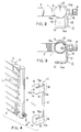
- the reference symbol "A" denotes a heat exchanger body which comprises a plurality of flat and horizontal aluminum tubes 1 stacked one on another, a plurality of aluminum fin members 2 each interposed between two adjacent tubes 1 and 1, and a pair of left and right headers 5 and 6 which are disposed at both ends of the tubes and fin members.
- the tubes 1 are made of a flat extruded profile of an aluminum material.
- the so-called harmonica tube of a perforated shape may alternatively be used to provide such tubes 1.
- Each fin member 2 is a corrugated fin which is repeatedly bent in a serpentine shape and is brazed to the adjacent tubes. It is preferable to employ fin members which have louvers opened up.
- Brazed to the outermost corrugated fins 2 are aluminum side plates 3 and 4 respectively positioned outside the fins 2.
- Each of the headers 5 and 6 is an aluminum of a substantially circular cross section.
- Each hollow header 5 and 6 has a plurality of tube insertion apertures 5a or 6a. Both ends of each tube 1 are inserted in the apertures and liquid-tightly brazed thereto. It is recommended to make the headers 5 and 6 from a seam-welded pipe which in turn is manufactured from a brazing sheet with its inner and/or outer surfaces coated with a brazing agent.
- the fin members 2 may also be made of the brazing sheet so that the tubes 1, the fin members 2, the side plates 3 and 4 and the headers 5 and 6 may be integrated with each other by the so-called "one-shot" brazing process within a vacuum heating oven. A higher productivity will be realized in such a case.
- the reference numeral 7 and 8 respectively denote a coolant inlet and a coolant outlet.
- the further numeral 9 denotes horizontal partitions tightly fixed in the headers so as to divide them into longitudinal chambers.
- a coolant flows into the heat exchanger body "A" through the inlet 7, and advances through coolant passageways within the heat exchanger body before flowing out of it.
- the coolant will exchange its heat with that of air, which is flowing through air paths formed between two tubes 1 and 1 and including the fin member 2. As a result of the heat exchange, the coolant will be condensed to become a liquid.
- Fasteners 10 and 11 of an aluminum alloy are secured the left and right headers 5 and 6, respectively, so as to rigidly connect the heat exchanger body "A" to receiving members formed for example on an automobile body.
- fasteners 10 and 11 are symmetrical with each other, only the right fastener 11 will be described below referring to the reference numerals which are also given to the corresponding portions of the left fastener 10.
- the fastener comprises a concave contacting member 12 which extends a predetermined distance along the header 6 and is in contact with about a fourth of the outer periphery of the header.
- the fastener further comprises: extensions 13 protruding tangentially of the header from side edges of an upper and lower portions of the concave contacting member; tabs 14 respectively extending from extremities of the extensions 13 and in parallel with the tubes 1; and ears 15 each protruding towards the header from and perpendicular to an upper edge of the tab 14.
- Each ear 15 has intermediate its side edges a tip end 15a of a convex shape enabling a tight contact thereof with a corresponding portion of the outer periphery of the header 6, as shown in Fig. 2. Another end extends from and slants to the tip end 15a so that the tip end can readily be snapped into its place.
- the concave contacting member 12 and the tip end 15a of the ear 15 will take their self-retaining position when they cooperate with each other to grip the header 6.
- the fastener 11 may be deemed to be composed of a pair of embracing portions 16 and a tie rod or beam connecting them one to another.
- One of the tabs 14 has a hole 14a formed through its central portion, and a bolt or the like may be inserted in the hole so as to fasten the heat exchanger to an automobile body or the like.
- the concave contacting member 12 has a lug 12a protruding towards the header 6, as shown in Fig. 3.
- the header 6 has an opening 6b corresponding to and engageable with the lug so that the position of the fastener 11 self-retaining and embracing the header 6 can be readily and accurately controlled relative to the header by fitting the lug 12a in the opening 6b.
- the attaching of the fastener 11 to the header 6 is carried out by forcibly urging the former 11 towards the latter and thereby causing the header 6 to be grasped between the concave contacting member 12 and the ear's 15 tip end 15a, wherein the lug 12a of said member 12 engages with the positioning opening 6b of the header 6 in order to ensure the accurate position of the fastener 11 self-retaining on said header.
- the fasteners 10 and 11 which are self-retaining on the respective headers 5 and 6 in this manner without needing any auxiliary means, will then be brought into an oven together with the heat exchanger body "A". All the above-mentioned members will be brazed in their positions one to another to thereby provided a finished heat exchanger, which in use will be fixed to receiving members of for example the automobile body.
- FIG. 5 illustrates in part a second embodiment of the invention.
- a connector 27 as a connecting means protrudes from a side edge at a middle height of the contacting member 22, and has a hole 27a for insertion of a bolt or the like.
- a bulging reinforcing rib 27b is formed integral with and along the connector 27, at its central portion.
- the header 6 has a positioning lug 6c, while the contacting member 22 of the fastener 21 has an opening 22a corresponding to and engageable with the lug 6c, in a manner contrary to that in the first embodiment.
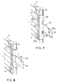
- Fig. 7 shows a fastener 31 in accordance with a third embodiment of the invention.
- the fastener 31 which is also an integral piece of pressed aluminum alloy, comprises a concave contacting member 32 of a given length, embracing portions 36 and 36, and a connecting means.
- the contacting member 32 is adapted to come into a tight contact with the header 6.
- the embracing portions 36 are capable of tightly holding the header 6 over a little more than a half periphery thereof.
- the connecting means is a connector 37 integral with and protruding from the contacting member's 32 portion intermediate the embracing portions.
- a hole 37a for insertion of a bolt or the like is also formed through the connector 37.
- this fastener 31 has a positioning lug 32a which protrudes inwards from the concave contacting member 32 in correspondence with an opening 6b of the header 6, whereby the fastener can take a correct position.
- Fig. 8 shows a further embodiment of the invention, in which a fastener 41 comprises an embracing portion 46 adapted to tightly hold the header 6, over a little more than a half periphery and along a given adequate length thereof.
- a connector 47 as a connecting means is spot-welded at its base end to a vertical middle zone of the embracing portion.
- these lug and hole can be dispensed with.
- the invention may be applied also to a radiator or any other heat exchangers, though the embodiments relate to a condenser used in car air conditioner system.
- any embracing structure other than those which have been described above may be employed insofar as the fastener can be forcibly fitted on the header, from its side surface, so as to tightly embrace it in the fastener and to thereby establish a self-retaining state.
- the heat exchanger provided by the invention comprises the fastener which can be snapped to the side of header into the self-retaining and engaging state, so that the fastener is temporarily and fixedly attached to the heat exchanger body, without any auxiliary means being used, before "one-shot” brazing in the oven.
- the operation in manufacture of heat exchanger is rendered much easier than in the prior art process.
- the drawback that the auxiliary means would otherwise occupy a larger space within the oven will be eliminated in the invention, thereby a greater number of temporarily assembled heat exchangers can be accommodated in one oven, thus improving to a remarkable degree the productivity in manufacture of the heat exchanger.
- the brazing process is effective to make permanent the self-retaining position of the embracing portion of the fastener. Therefore, the heat exchanger body can be secured, with a sufficient strength, to for example the automobile's portion for receiving the heat exchanger.
Applications Claiming Priority (2)
| Application Number | Priority Date | Filing Date | Title |
|---|---|---|---|
| JP295709/90 | 1990-10-31 | ||
| JP2295709A JP3014434B2 (ja) | 1990-10-31 | 1990-10-31 | 熱交換器 |
Publications (2)
| Publication Number | Publication Date |
|---|---|
| EP0484004A1 true EP0484004A1 (fr) | 1992-05-06 |
| EP0484004B1 EP0484004B1 (fr) | 1995-03-29 |
Family
ID=17824145
Family Applications (1)
| Application Number | Title | Priority Date | Filing Date |
|---|---|---|---|
| EP91309535A Expired - Lifetime EP0484004B1 (fr) | 1990-10-31 | 1991-10-16 | Echangeur de chaleur |
Country Status (7)
| Country | Link |
|---|---|
| US (1) | US5183103A (fr) |
| EP (1) | EP0484004B1 (fr) |
| JP (1) | JP3014434B2 (fr) |
| AT (1) | ATE120537T1 (fr) |
| AU (1) | AU644234B2 (fr) |
| DE (1) | DE69108515T2 (fr) |
| ES (1) | ES2071931T3 (fr) |
Cited By (9)
| Publication number | Priority date | Publication date | Assignee | Title |
|---|---|---|---|---|
| DE4232019C1 (de) * | 1992-09-24 | 1993-10-28 | Thermal Waerme Kaelte Klima | Halterung an einem Wärmetauscher für Kraftfahrzeuge |
| DE4232018A1 (de) * | 1992-09-24 | 1994-03-31 | Thermal Waerme Kaelte Klima | Halterung an einem Sammler eines Wärmetauschers |
| FR2778974A1 (fr) * | 1998-05-25 | 1999-11-26 | Valeo Thermique Moteur Sa | Echangeur de chaleur, en particulier condenseur de vehicule automobile, et procede pour sa fabrication |
| EP1128150A2 (fr) * | 2000-02-25 | 2001-08-29 | Modine Manufacturing Company | Support de montage pour collecteur d'échangeur de chaleur et sa méthode d'assemblage |
| FR2807153A1 (fr) * | 2000-04-03 | 2001-10-05 | Ebea S A | Procedure de fabrication des moyens de connexion d'un echangeur thermique, bloc de raccordement et tube collecteur associes |
| EP1491840A3 (fr) * | 2003-06-25 | 2005-01-05 | Delphi Technologies, Inc. | Patte de fixation sans attache pour échangeur de chaleur |
| WO2008094986A2 (fr) | 2007-01-31 | 2008-08-07 | Dow Global Technologies, Inc. | Sequences leader bacteriennes pour augmenter l'expression |
| EP1956333A1 (fr) * | 2007-02-06 | 2008-08-13 | Behr France Hambach S.A.R.L. | Agent caloporteur, en particulier condenseur pour climatiseur de véhicules automobiles |
| WO2016041131A1 (fr) * | 2014-09-15 | 2016-03-24 | Trane Air Conditioning Systems (China) Co., Ltd. | Attache de montage |
Families Citing this family (37)
| Publication number | Priority date | Publication date | Assignee | Title |
|---|---|---|---|---|
| FR2690234B1 (fr) * | 1992-04-16 | 1994-06-03 | Valeo Thermique Moteur Sa | Dispositif pour la fixation d'un echangeur de chaleur a boite collectrice tubulaire. |
| US5456089A (en) * | 1993-03-24 | 1995-10-10 | Tripac, Inc. | Universal condenser for an air conditioning system |
| US5664432A (en) * | 1993-03-24 | 1997-09-09 | Tripac International, Inc. | Vehicle air conditioning condenser |
| US5407161A (en) * | 1993-03-25 | 1995-04-18 | Valeo Engine Cooling, Inc. | Bracket to be secured to a cylindrical object |
| US5487422A (en) * | 1994-01-25 | 1996-01-30 | Wynns Climate Systems, Inc. | Mounting bracket for a heat exchanger |
| US5826646A (en) * | 1995-10-26 | 1998-10-27 | Heatcraft Inc. | Flat-tubed heat exchanger |
| JPH10206068A (ja) * | 1997-01-17 | 1998-08-07 | Sanden Corp | 熱交換器用ブラケット |
| US6823932B2 (en) * | 2001-05-25 | 2004-11-30 | Modine Manufacturing Company | Self-fixturing side piece for brazed heat exchangers |
| CA2366227C (fr) | 2001-12-27 | 2007-12-04 | John W. Izard | Support de fixation pour faisceaux d'echangeur de chaleur |
| US7055582B2 (en) * | 2002-10-15 | 2006-06-06 | Tecumseh Products Company | Refrigerating unit having heat-exchanger mounting shroud |
| PL360511A1 (en) | 2003-06-05 | 2004-12-13 | Delphi Technologies, Inc. | Self-acting snap fastening assembly bracket |
| CA2433975C (fr) * | 2003-06-27 | 2012-01-17 | Dana Canada Corporation | Support de montage a nervures pour echangeurs de chaleur |
| CA2433697A1 (fr) | 2003-06-27 | 2004-12-27 | Dana Canada Corporation | Support de fixation resistant aux vibrations pour echangeurs thermiques |
| DE10344219A1 (de) * | 2003-09-22 | 2005-04-14 | Behr Gmbh & Co. Kg | Wärmeübertragermodul für ein Kraftfahrzeug |
| US7051789B2 (en) * | 2004-04-22 | 2006-05-30 | Dana Canada Corporation | Two-piece mounting bracket for heat exchanger |
| US7320360B2 (en) * | 2004-11-12 | 2008-01-22 | Delphi Technologies, Inc. | One-shot brazed aftercooler with hollow beam reinforced mounting feature |
| US7874349B2 (en) * | 2006-03-16 | 2011-01-25 | Visteon Global Technologies, Inc. | Heat exchanger tank |
| DE102006036833B4 (de) * | 2006-08-07 | 2012-12-13 | Siemens Ag | Gradientenspulensystem und Magnetresonanztomograph |
| CA2590170C (fr) | 2007-05-28 | 2014-08-19 | Dana Canada Corporation | Support de fixation pour echangeur thermique |
| JP2009085569A (ja) * | 2007-10-03 | 2009-04-23 | Denso Corp | 蒸発器ユニット |
| DE102007051128A1 (de) * | 2007-10-24 | 2009-04-30 | Behr Gmbh & Co. Kg | Wärmeübertrager, insbesondere Kondensator für Klimaanlagen und Anordnung zur Befestigung eines Wärmeübertragers |
| US20100132917A1 (en) * | 2008-12-02 | 2010-06-03 | Delphi Technologies, Inc. | Snap Lock A-Frame Heat Exchanger Bracket |
| DE102009056508A1 (de) * | 2009-12-02 | 2011-06-09 | Behr Gmbh & Co. Kg | Kühlmodul und Adapterpaar für Modulvereinheitlichung |
| KR200469968Y1 (ko) * | 2011-02-01 | 2013-12-19 | 양재영 | 수상스키 전용 가방 |
| US8840076B2 (en) * | 2011-11-18 | 2014-09-23 | Denso International America, Inc. | Enhanced surface area for sideplate heat exchanger bracket |
| JP6048231B2 (ja) * | 2013-03-11 | 2016-12-21 | マツダ株式会社 | 車両のラジエータ支持装置 |
| USD717218S1 (en) * | 2014-07-24 | 2014-11-11 | Resource Intl, Inc. | Automotive radiator |
| USD746732S1 (en) * | 2015-09-04 | 2016-01-05 | Randall Industries, Inc. | Bolt-on radiator |
| USD751472S1 (en) * | 2015-09-08 | 2016-03-15 | Randall Industries, Inc. | Bolt-on radiator |
| EP3290848B1 (fr) | 2016-09-02 | 2020-05-06 | Modine Manufacturing Company | Collecteur pour un échangeur de chaleur et son procédé de fabrication |
| JP6820750B2 (ja) * | 2017-01-04 | 2021-01-27 | 日立ジョンソンコントロールズ空調株式会社 | 室外機、および冷凍サイクル装置 |
| USD921043S1 (en) * | 2018-09-12 | 2021-06-01 | Resource International Inc. | Radiator for automotive applications |
| USD912702S1 (en) * | 2018-09-12 | 2021-03-09 | Resource International Inc. | Radiator for automotive applications |
| USD905759S1 (en) * | 2018-09-27 | 2020-12-22 | Resource International Inc. | Radiator for automotive applications |
| USD891318S1 (en) * | 2018-10-24 | 2020-07-28 | Specialty Auto Parts U.S.A., Inc. | Coolant radiator core |
| USD913335S1 (en) * | 2019-07-26 | 2021-03-16 | Resource International Inc. | Radiator for automotive applications |
| US11338666B2 (en) * | 2020-03-05 | 2022-05-24 | Denso International America, Inc. | Heat exchanging system |
Citations (2)
| Publication number | Priority date | Publication date | Assignee | Title |
|---|---|---|---|---|
| US4651816A (en) * | 1986-03-19 | 1987-03-24 | Modine Manufacturing Company | Heat exchanger module for a vehicle or the like |
| US4903389A (en) * | 1988-05-31 | 1990-02-27 | General Motors Corporation | Heat exchanger with laminated header and method of manufacture |
Family Cites Families (5)
| Publication number | Priority date | Publication date | Assignee | Title |
|---|---|---|---|---|
| US2331634A (en) * | 1941-12-20 | 1943-10-12 | Young Radiator Co | Convector heater |
| US3121467A (en) * | 1960-09-01 | 1964-02-18 | Gen Motors Corp | Resiliently mounted radiator assembly |
| DE2304883A1 (de) * | 1973-02-01 | 1974-08-08 | Buderus Eisenwerk | Halterung fuer einen heizkoerper |
| WO1984001208A1 (fr) * | 1982-09-24 | 1984-03-29 | Bryce H Knowlton | Assemblage ameliore de radiateur |
| JP3043025B2 (ja) * | 1990-02-01 | 2000-05-22 | 昭和アルミニウム株式会社 | 熱交換器 |
-
1990
- 1990-10-31 JP JP2295709A patent/JP3014434B2/ja not_active Expired - Fee Related
-
1991
- 1991-10-16 EP EP91309535A patent/EP0484004B1/fr not_active Expired - Lifetime
- 1991-10-16 DE DE69108515T patent/DE69108515T2/de not_active Expired - Fee Related
- 1991-10-16 ES ES91309535T patent/ES2071931T3/es not_active Expired - Lifetime
- 1991-10-16 AT AT91309535T patent/ATE120537T1/de not_active IP Right Cessation
- 1991-10-28 US US07/782,984 patent/US5183103A/en not_active Expired - Lifetime
- 1991-10-29 AU AU86850/91A patent/AU644234B2/en not_active Ceased
Patent Citations (2)
| Publication number | Priority date | Publication date | Assignee | Title |
|---|---|---|---|---|
| US4651816A (en) * | 1986-03-19 | 1987-03-24 | Modine Manufacturing Company | Heat exchanger module for a vehicle or the like |
| US4903389A (en) * | 1988-05-31 | 1990-02-27 | General Motors Corporation | Heat exchanger with laminated header and method of manufacture |
Cited By (15)
| Publication number | Priority date | Publication date | Assignee | Title |
|---|---|---|---|---|
| DE4232019C1 (de) * | 1992-09-24 | 1993-10-28 | Thermal Waerme Kaelte Klima | Halterung an einem Wärmetauscher für Kraftfahrzeuge |
| DE4232018A1 (de) * | 1992-09-24 | 1994-03-31 | Thermal Waerme Kaelte Klima | Halterung an einem Sammler eines Wärmetauschers |
| US6422302B1 (en) | 1998-05-25 | 2002-07-23 | Valeo Thermique Moteur | Heat exchanger, in particular motor vehicle condenser and method for making same |
| WO1999061859A1 (fr) * | 1998-05-25 | 1999-12-02 | Valeo Thermique Moteur | Echangeur de chaleur, en particulier condenseur de vehicule automobile, et procede pour sa fabrication |
| FR2778974A1 (fr) * | 1998-05-25 | 1999-11-26 | Valeo Thermique Moteur Sa | Echangeur de chaleur, en particulier condenseur de vehicule automobile, et procede pour sa fabrication |
| EP1128150A2 (fr) * | 2000-02-25 | 2001-08-29 | Modine Manufacturing Company | Support de montage pour collecteur d'échangeur de chaleur et sa méthode d'assemblage |
| EP1128150A3 (fr) * | 2000-02-25 | 2002-10-23 | Modine Manufacturing Company | Support de montage pour collecteur d'échangeur de chaleur et sa méthode d'assemblage |
| FR2807153A1 (fr) * | 2000-04-03 | 2001-10-05 | Ebea S A | Procedure de fabrication des moyens de connexion d'un echangeur thermique, bloc de raccordement et tube collecteur associes |
| EP1491840A3 (fr) * | 2003-06-25 | 2005-01-05 | Delphi Technologies, Inc. | Patte de fixation sans attache pour échangeur de chaleur |
| US6901992B2 (en) | 2003-06-25 | 2005-06-07 | Delphi Technologies, Inc. | Fastenerless mounting bracket for heat exchangers |
| WO2008094986A2 (fr) | 2007-01-31 | 2008-08-07 | Dow Global Technologies, Inc. | Sequences leader bacteriennes pour augmenter l'expression |
| EP2468869A1 (fr) | 2007-01-31 | 2012-06-27 | Pfenex, Inc. | Séquences leader bactériennes pour augmenter l'expression |
| EP1956333A1 (fr) * | 2007-02-06 | 2008-08-13 | Behr France Hambach S.A.R.L. | Agent caloporteur, en particulier condenseur pour climatiseur de véhicules automobiles |
| WO2016041131A1 (fr) * | 2014-09-15 | 2016-03-24 | Trane Air Conditioning Systems (China) Co., Ltd. | Attache de montage |
| US10234215B2 (en) | 2014-09-15 | 2019-03-19 | Trane International Inc. | Mounting clip |
Also Published As
| Publication number | Publication date |
|---|---|
| ES2071931T3 (es) | 1995-07-01 |
| EP0484004B1 (fr) | 1995-03-29 |
| AU644234B2 (en) | 1993-12-02 |
| ATE120537T1 (de) | 1995-04-15 |
| DE69108515T2 (de) | 1995-08-03 |
| AU8685091A (en) | 1992-05-07 |
| US5183103A (en) | 1993-02-02 |
| JP3014434B2 (ja) | 2000-02-28 |
| DE69108515D1 (de) | 1995-05-04 |
| JPH04169793A (ja) | 1992-06-17 |
Similar Documents
| Publication | Publication Date | Title |
|---|---|---|
| EP0484004B1 (fr) | Echangeur de chaleur | |
| US5632332A (en) | Heat exchanger having inlet and outlet pipes for a heat exchanging medium and a method of making same | |
| JP2747379B2 (ja) | 熱交換器 | |
| US5069275A (en) | Heat exchanger | |
| JP2537507Y2 (ja) | 熱交換器 | |
| US5363910A (en) | Heat exchanger | |
| JP3760571B2 (ja) | 熱交換器 | |
| US6742572B2 (en) | Mounting bracket for heat exchanger cores | |
| JPH06159981A (ja) | 熱交換器 | |
| US11493283B2 (en) | B-tube reform for improved thermal cycle performance | |
| EP1308688A2 (fr) | Ensemble collecteur-plaque tubulaire pour échangeur de chaleur | |
| JP3004253U (ja) | 冷媒を液化するためのコンデンサー | |
| US7302997B2 (en) | Vibration-resistant mounting bracket for heat exchangers | |
| JPH0571876B2 (fr) | ||
| EP1219913A2 (fr) | Joue latérale améliorée pour échangeur de chaleur | |
| US20030159813A1 (en) | Heat exchanger manifold and method of assembly | |
| JP2898800B2 (ja) | 熱交換器 | |
| JP3212038B2 (ja) | アルミニウム製熱交換器 | |
| JPH04363591A (ja) | 熱交換器 | |
| JP2578557B2 (ja) | 熱交換器 | |
| JPH04278196A (ja) | 熱交換器 | |
| JP3133431B2 (ja) | 熱交換器 | |
| JP2831578B2 (ja) | ブラケットを備えた熱交換器の製造方法 | |
| JPH02247498A (ja) | 熱交換器 | |
| JP2515739Y2 (ja) | 熱交換器 |
Legal Events
| Date | Code | Title | Description |
|---|---|---|---|
| PUAI | Public reference made under article 153(3) epc to a published international application that has entered the european phase |
Free format text: ORIGINAL CODE: 0009012 |
|
| AK | Designated contracting states |
Kind code of ref document: A1 Designated state(s): AT CH DE ES FR GB IT LI SE |
|
| 17P | Request for examination filed |
Effective date: 19920609 |
|
| 17Q | First examination report despatched |
Effective date: 19921030 |
|
| GRAA | (expected) grant |
Free format text: ORIGINAL CODE: 0009210 |
|
| AK | Designated contracting states |
Kind code of ref document: B1 Designated state(s): AT CH DE ES FR GB IT LI SE |
|
| REF | Corresponds to: |
Ref document number: 120537 Country of ref document: AT Date of ref document: 19950415 Kind code of ref document: T |
|
| ITF | It: translation for a ep patent filed |
Owner name: MANZONI & MANZONI |
|
| REF | Corresponds to: |
Ref document number: 69108515 Country of ref document: DE Date of ref document: 19950504 |
|
| REG | Reference to a national code |
Ref country code: ES Ref legal event code: FG2A Ref document number: 2071931 Country of ref document: ES Kind code of ref document: T3 |
|
| ET | Fr: translation filed | ||
| PLBE | No opposition filed within time limit |
Free format text: ORIGINAL CODE: 0009261 |
|
| STAA | Information on the status of an ep patent application or granted ep patent |
Free format text: STATUS: NO OPPOSITION FILED WITHIN TIME LIMIT |
|
| 26N | No opposition filed | ||
| REG | Reference to a national code |
Ref country code: GB Ref legal event code: 732E |
|
| REG | Reference to a national code |
Ref country code: GB Ref legal event code: IF02 |
|
| REG | Reference to a national code |
Ref country code: FR Ref legal event code: TP |
|
| REG | Reference to a national code |
Ref country code: CH Ref legal event code: PFA Free format text: SHOWA ALUMINUM KABUSHIKI KAISHA TRANSFER- SHOWA DENKO K.K. |
|
| PGFP | Annual fee paid to national office [announced via postgrant information from national office to epo] |
Ref country code: SE Payment date: 20021004 Year of fee payment: 12 |
|
| PGFP | Annual fee paid to national office [announced via postgrant information from national office to epo] |
Ref country code: AT Payment date: 20021011 Year of fee payment: 12 |
|
| PGFP | Annual fee paid to national office [announced via postgrant information from national office to epo] |
Ref country code: CH Payment date: 20021016 Year of fee payment: 12 |
|
| PGFP | Annual fee paid to national office [announced via postgrant information from national office to epo] |
Ref country code: ES Payment date: 20021031 Year of fee payment: 12 |
|
| PG25 | Lapsed in a contracting state [announced via postgrant information from national office to epo] |
Ref country code: AT Free format text: LAPSE BECAUSE OF NON-PAYMENT OF DUE FEES Effective date: 20031016 |
|
| PG25 | Lapsed in a contracting state [announced via postgrant information from national office to epo] |
Ref country code: SE Free format text: LAPSE BECAUSE OF NON-PAYMENT OF DUE FEES Effective date: 20031017 Ref country code: ES Free format text: LAPSE BECAUSE OF NON-PAYMENT OF DUE FEES Effective date: 20031017 |
|
| PG25 | Lapsed in a contracting state [announced via postgrant information from national office to epo] |
Ref country code: LI Free format text: LAPSE BECAUSE OF NON-PAYMENT OF DUE FEES Effective date: 20031031 Ref country code: CH Free format text: LAPSE BECAUSE OF NON-PAYMENT OF DUE FEES Effective date: 20031031 |
|
| EUG | Se: european patent has lapsed | ||
| REG | Reference to a national code |
Ref country code: CH Ref legal event code: PL |
|
| PGFP | Annual fee paid to national office [announced via postgrant information from national office to epo] |
Ref country code: FR Payment date: 20041008 Year of fee payment: 14 |
|
| PGFP | Annual fee paid to national office [announced via postgrant information from national office to epo] |
Ref country code: GB Payment date: 20041013 Year of fee payment: 14 |
|
| PGFP | Annual fee paid to national office [announced via postgrant information from national office to epo] |
Ref country code: DE Payment date: 20041014 Year of fee payment: 14 |
|
| REG | Reference to a national code |
Ref country code: ES Ref legal event code: FD2A Effective date: 20031017 |
|
| PG25 | Lapsed in a contracting state [announced via postgrant information from national office to epo] |
Ref country code: IT Free format text: LAPSE BECAUSE OF NON-PAYMENT OF DUE FEES;WARNING: LAPSES OF ITALIAN PATENTS WITH EFFECTIVE DATE BEFORE 2007 MAY HAVE OCCURRED AT ANY TIME BEFORE 2007. THE CORRECT EFFECTIVE DATE MAY BE DIFFERENT FROM THE ONE RECORDED. Effective date: 20051016 Ref country code: GB Free format text: LAPSE BECAUSE OF NON-PAYMENT OF DUE FEES Effective date: 20051016 |
|
| PG25 | Lapsed in a contracting state [announced via postgrant information from national office to epo] |
Ref country code: DE Free format text: LAPSE BECAUSE OF NON-PAYMENT OF DUE FEES Effective date: 20060503 |
|
| GBPC | Gb: european patent ceased through non-payment of renewal fee |
Effective date: 20051016 |
|
| PG25 | Lapsed in a contracting state [announced via postgrant information from national office to epo] |
Ref country code: FR Free format text: LAPSE BECAUSE OF NON-PAYMENT OF DUE FEES Effective date: 20060630 |
|
| REG | Reference to a national code |
Ref country code: FR Ref legal event code: ST Effective date: 20060630 |