EP0482825A2 - Verfahren und Gerät zum Befestigen von aufeinanderfolgenden Paaren von Drähten an einen Datenverbinder mit feinem Kontaktabstand - Google Patents
Verfahren und Gerät zum Befestigen von aufeinanderfolgenden Paaren von Drähten an einen Datenverbinder mit feinem Kontaktabstand Download PDFInfo
- Publication number
- EP0482825A2 EP0482825A2 EP91309592A EP91309592A EP0482825A2 EP 0482825 A2 EP0482825 A2 EP 0482825A2 EP 91309592 A EP91309592 A EP 91309592A EP 91309592 A EP91309592 A EP 91309592A EP 0482825 A2 EP0482825 A2 EP 0482825A2
- Authority
- EP
- European Patent Office
- Prior art keywords
- pair
- connector
- separate
- contact
- attachment
- Prior art date
- Legal status (The legal status is an assumption and is not a legal conclusion. Google has not performed a legal analysis and makes no representation as to the accuracy of the status listed.)
- Granted
Links
Images


Classifications
-
- H—ELECTRICITY
- H01—ELECTRIC ELEMENTS
- H01R—ELECTRICALLY-CONDUCTIVE CONNECTIONS; STRUCTURAL ASSOCIATIONS OF A PLURALITY OF MUTUALLY-INSULATED ELECTRICAL CONNECTING ELEMENTS; COUPLING DEVICES; CURRENT COLLECTORS
- H01R11/00—Individual connecting elements providing two or more spaced connecting locations for conductive members which are, or may be, thereby interconnected, e.g. end pieces for wires or cables supported by the wire or cable and having means for facilitating electrical connection to some other wire, terminal, or conductive member, blocks of binding posts
-
- H—ELECTRICITY
- H01—ELECTRIC ELEMENTS
- H01R—ELECTRICALLY-CONDUCTIVE CONNECTIONS; STRUCTURAL ASSOCIATIONS OF A PLURALITY OF MUTUALLY-INSULATED ELECTRICAL CONNECTING ELEMENTS; COUPLING DEVICES; CURRENT COLLECTORS
- H01R43/00—Apparatus or processes specially adapted for manufacturing, assembling, maintaining, or repairing of line connectors or current collectors or for joining electric conductors
- H01R43/01—Apparatus or processes specially adapted for manufacturing, assembling, maintaining, or repairing of line connectors or current collectors or for joining electric conductors for connecting unstripped conductors to contact members having insulation cutting edges
-
- Y—GENERAL TAGGING OF NEW TECHNOLOGICAL DEVELOPMENTS; GENERAL TAGGING OF CROSS-SECTIONAL TECHNOLOGIES SPANNING OVER SEVERAL SECTIONS OF THE IPC; TECHNICAL SUBJECTS COVERED BY FORMER USPC CROSS-REFERENCE ART COLLECTIONS [XRACs] AND DIGESTS
- Y10—TECHNICAL SUBJECTS COVERED BY FORMER USPC
- Y10T—TECHNICAL SUBJECTS COVERED BY FORMER US CLASSIFICATION
- Y10T29/00—Metal working
- Y10T29/49—Method of mechanical manufacture
- Y10T29/49002—Electrical device making
- Y10T29/49117—Conductor or circuit manufacturing
- Y10T29/49174—Assembling terminal to elongated conductor
- Y10T29/49181—Assembling terminal to elongated conductor by deforming
-
- Y—GENERAL TAGGING OF NEW TECHNOLOGICAL DEVELOPMENTS; GENERAL TAGGING OF CROSS-SECTIONAL TECHNOLOGIES SPANNING OVER SEVERAL SECTIONS OF THE IPC; TECHNICAL SUBJECTS COVERED BY FORMER USPC CROSS-REFERENCE ART COLLECTIONS [XRACs] AND DIGESTS
- Y10—TECHNICAL SUBJECTS COVERED BY FORMER USPC
- Y10T—TECHNICAL SUBJECTS COVERED BY FORMER US CLASSIFICATION
- Y10T29/00—Metal working
- Y10T29/51—Plural diverse manufacturing apparatus including means for metal shaping or assembling
- Y10T29/5193—Electrical connector or terminal
-
- Y—GENERAL TAGGING OF NEW TECHNOLOGICAL DEVELOPMENTS; GENERAL TAGGING OF CROSS-SECTIONAL TECHNOLOGIES SPANNING OVER SEVERAL SECTIONS OF THE IPC; TECHNICAL SUBJECTS COVERED BY FORMER USPC CROSS-REFERENCE ART COLLECTIONS [XRACs] AND DIGESTS
- Y10—TECHNICAL SUBJECTS COVERED BY FORMER USPC
- Y10T—TECHNICAL SUBJECTS COVERED BY FORMER US CLASSIFICATION
- Y10T29/00—Metal working
- Y10T29/53—Means to assemble or disassemble
- Y10T29/5313—Means to assemble electrical device
- Y10T29/532—Conductor
- Y10T29/53209—Terminal or connector
- Y10T29/53213—Assembled to wire-type conductor
- Y10T29/53217—Means to simultaneously assemble multiple, independent conductors to terminal
-
- Y—GENERAL TAGGING OF NEW TECHNOLOGICAL DEVELOPMENTS; GENERAL TAGGING OF CROSS-SECTIONAL TECHNOLOGIES SPANNING OVER SEVERAL SECTIONS OF THE IPC; TECHNICAL SUBJECTS COVERED BY FORMER USPC CROSS-REFERENCE ART COLLECTIONS [XRACs] AND DIGESTS
- Y10—TECHNICAL SUBJECTS COVERED BY FORMER USPC
- Y10T—TECHNICAL SUBJECTS COVERED BY FORMER US CLASSIFICATION
- Y10T29/00—Metal working
- Y10T29/53—Means to assemble or disassemble
- Y10T29/5313—Means to assemble electrical device
- Y10T29/532—Conductor
- Y10T29/53209—Terminal or connector
- Y10T29/53213—Assembled to wire-type conductor
- Y10T29/53235—Means to fasten by deformation
Definitions
- This invention relates to a machine, and its method of use, for attaching successive pairs of wires in a cable to successive pairs of opposed, closely spaced contacts in a data connector.
- multiconductor cables are still widely employed to interconnect two pieces of electronic equipment.
- the cable usually has each of its ends terminated by a connector designed to mate with a complementary connector on the piece of equipment to be connected to the cable.
- a large majority of the connectors employed to terminate the ends of a multiconductor cable are comprised of two rows of opposed contacts held in an insulative member, usually made of plastic or the like.
- Each contact in the connector typically has a first end adapted to mate with a corresponding contact of another connector, and a second end provided with a wire-piercing barb. Attachment of a wire to a corresponding one of the contacts of the connector is accomplished by ramming a wire against the barb on the contact until the barb pierces the wire to make an electrical connection with the metal conductor inside it.
- an improved connector attachment apparatus comprised of a base plate having a connector-carrying carriage slidably mounted to the base plate for movement along a first axis.
- a separate one of a pair of ram assemblies each having a knife blade movable to and from the carriage to ram a wire against one of a pair of opposed contacts in the connector carried by the carriage.
- the knife blade of each ram assembly is provided with a contact protector assembly spring-biased to, and extending forward from, the knife for straddling the contact.
- a wire guide is provided adjacent to each of the ram assemblies for guiding a separate one of a pair of wires with the knife blade of a corresponding one of the ram assemblies.
- a carriage advancement mechanism is provided for advancing the carriage to align each of a successive pair of opposed contacts with a separate one of the ram assemblies.
- a connector attachment tool for both attaching successive pairs of wires to successive pairs of opposed contacts of a connector as well as for attaching at least one strain relief, and preferably two strain reliefs, one on each side of the connector, following wire attachment.
- the connector attachment apparatus includes a mechanism for attaching at least one, and preferably a pair of, strain reliefs to the connector following attachment of successive pairs of wires to successive pairs of contacts in the connector.
- the strain relief attachment mechanism comprises at least one and, preferably, a pair of hoppers, each located downstream of a separate one of the ram assemblies on opposite sides of the path of carriage movement. Each hopper is generally comprised of a pair of spaced-apart uprights for holding a stack of strain reliefs.
- each of a pair of strain reliefs may be attached without the need to remove the connector from the connector attachment apparatus, thereby minimizing the need to manually handle the connector prior to attachment of the strain reliefs.
- the present invention is directed to an apparatus for attaching successive pairs of wires to successive pairs of opposed, closely spaced (e.g. "fine-pitch") contacts in a data connector.
- fine-pitch e.g. "fine-pitch" contacts
- FIG. 1 there is shown an exploded view of a data connector 10 according to the prior art.
- the connector 10 is comprised of an insulative member 12, made from plastic or the like, with a lower portion 13, as seen in FIG. 1, which is generally prismatic in shape, with rounded comers, to facilitate mating with a complementary connector of the same variety and an upper portion 14.
- the upper portion 14 of the member 12 is shaped in the form of a long, thin prismatic wall, having a separate one of a pair of ears 16 at each of its ends.
- Each of the ears 16 has a passage 18 extending horizontally therethrough whose purpose will become better understood hereinafter.
- the wall 14 serves to separate each of a pair of rows of closely spaced electrical contacts 20 from the other.
- Each of the contacts 20 in each row is comprised of a shaft 22 which extends into the lower portion 13 of the member 12 to make an electrical connection with a contact on a connector mating with the connector 10.
- a barb 23 Integral with the upper end of the shaft 22 is a barb 23 comprised of a thin horizontal portion having a V-shaped slot 24 designed to pierce the insulation on a wire 25 rammed into the slot.
- the center-to-center spacing of the contacts 20 in each row is made small, typically on the order of 50 mils. For this reason, the connector 10 is said to have "fine-pitch" contacts 20. In order to facilitate such close spacing, the size and bulk of the shaft 22 as well the barb 23 of each contact 20 are reduced. Further, the height of the barbs on the contacts 20 is staggered so that every other barb lies below each of its neighbors on opposite sides.
- each of a left-hand and right-hand pair of strain reliefs 26 and 28 is attached to the right-hand and left-hand one of the sides, respectively, of the wall 14 so as to overlie the contacts in the row on the corresponding side of the wall.
- each of the strain reliefs 26 and 28 comprises a bar 30, made from plastic or the like, and having either a square or rectangular cross section.
- the bar 30 has a raised lip 32 on its upper surface, the ends of the lip being spaced a short distance from the ends of the bar.
- the lip 32 semes to impart a particular shape to the bar 30 such that when the lip is facing upward, the bar is said to be right-side up.
- On a first longitudinal face 34 of the bar 30 of each of the strain reliefs 26 and 28 is a plurality of half-rounded vertical channels 36 spaced apart a distance about the same as the contacts 20 in each row on the connector 10.
- the channels 36 each seme to partially seat a separate one of the wires 25 rammed against each contact 20 when each of the strain reliefs 26, 28 overlies a separate one of the right-hand and left- hand row of contacts.
- Each of the strain reliefs 26 and 28 is attached to the connector 10 by way of a pair of half-rounded cylindrical posts 38 which extend horizontally outwardly from the face 34 of the bar 30 for receipt in a separate one of the passages 18 in the ears 16 in the wall 14.
- the posts 38 on the right-hand strain relief 26 are oriented such that each has its flat face looking leftward in the figure while the posts on the left-hand strain relief 28 have their flat face looking rightward. In this way, there will be no interference when each of the right-hand and left-hand posts 38 of both strain reliefs 26 and 28 are received in a separate one of the right-hand and left- hand passages 18.
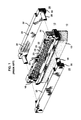
- FIGS. 2 and 3 there is shown an apparatus 40, in accordance with the present invention, for attaching each of a successive pair of wires 25 to each of a successive pair of opposed contacts 20 (see FIG. 1 ) in the connector 10 and for attaching each of the right-hand and left-hand strain reliefs 26 and 28 (see FIG. 1) to the connector as well.
- the connector attachment apparatus 40 is generally similar to that disclosed in the Billingham et al. U.S. patent 4,903,399, herein incorporated by reference.
- the connector attachment apparatus 40 includes a base plate 42 which mounts an upwardly rising wall 44 that runs on the plate along a first axis 46.
- a slot 48 which runs along the axis 46.
- the slot 48 serves to receive a connector-carrying carriage 50 slidably mounted for movement in the wall 44 along the axis 46.
- a mechanism 52 is provided for incrementally displacing the carriage 50 along the wall 44.
- Each of a pair of ram assemblies 54 is mounted to the base plate 40 perpendicular to, and on opposite sides of, the wall 44 so as to lie on opposite sides of the path of travel of the carriage 50.
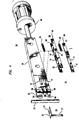
- Each of the ram assemblies 54 includes a knife blade 56 (see FIG. 4) slidably mounted within a housing 58 (see FIG. 2) for movement to and from the carriage 50 along an axis perpendicular to the axis 46.
- the knife blade 56 of FIG. 4 is reciprocated to and from the carriage 50 by an actuator 60, which, in a preferred embodiment, takes the form of an air cylinder.
- the air cylinder 60 of each ram assembly 54 is actuated in unison with the air cylinder associated with the other ram assembly.
- the knife blades 56 are displaced forward towards the connector 10 to attach each of a pair of wires 25 to each of a pair of opposed contacts 20 (see FIG. 1).
- a separate one of a pair of wire guides 61 is situated adjacent to each ram assembly 54 to align a wire with the forward end of the knife blade 56.
- the knife blade 56 of each ram assembly 54 has a vertically running concavity 62 at its forward (leftward) end.
- the concavity 62 at the forward end of each knife blade 56 serves to partially seat the wire 25 to be rammed into the slot 24 on the barb 23 of the contact 20 to maintain the wire centered with the slot.
- the knife blade 56 of each ram assembly 54 is advantageously provided with a contact protector assembly 64 in accordance with the invention.
- the contact protector assembly 64 comprises upper and lower, generally "H-shaped" members 66 and 67, the lower member only being partially illustrated in FIG. 4.
- the members 66 and 67 are each configured of a pair of prismatic strips 68 which each have a block-like projection 70 extending horizontally outwardly from a first longitudinal side 71 thereof for abutment with, and attachment to, the block-like projection of the other strip, thus establishing the H-shaped configuration of each member.
- the blade is provided with an elongated slot 72 a short distance rearward of the concavity 62, the slot being sized to accommodate the projection 70 on each of the strips.
- a second elongated slot 74 is provided in the knife blade 56 directly below the slot 72 to accommodate the projection 70 on each of the strips 68 of the second member 67 (only one such strip is illustrated in FIG. 4).
- the height of the slots 72 and 74 corresponds to the height of the upper and lower barbs 23 in a separate one of the rows of the contacts 20 in the connector 10 of FIG. 1.
- a threaded fastener 76 extends through the projection on the right-hand one of the strips 68 of each of the members 66 and 67 into the projection 70 of the other strip of the same member to secure the strips together after the strips have been situated on opposite sides of the knife blade 56.
- Each of a pair of compression springs 78 and 80 is interposed between a separate one of the members 66 and 67 and the rearward wall of a separate one of the slots 72 and 74, respectively, to bias the member forward of the knife blade 56.
- each strip 68 of each of the members 66 and 67 Extending horizontally outward from the face 71 of each strip 68 of each of the members 66 and 67 is a second projection 82 which is forward (leftward) of the first projection 70.
- the second projections 82 on the strips 68 of the first member 66 each ride in a separate one of a first pair of grooves 84, located on opposite sides of the knife blade 56, forward of, and at the same height as, the slot 72.
- the second projections 82 on the strips 68 of the second member 67 each ride in a separate one of a pair of grooves 86 situated on opposite sides of the knife blade 56 directly below a separate one of the grooves 84.
- the grooves 84 and 86 each serve to maintain a separate one of the members 66 and 67 parallel to the horizontal axis of the blade 56, so as to guide that member when biased rearwardly along the blade in a manner described below.
- FIG. 5A is a plan view of a portion of the connector 10 (see FIG. 1 ) at the outset of the wire attachment process.
- the particular barb 23 to which the wire 25 is being attached is at the same height as the member 66, so only the operation of that member will be described, it being understood that the member 67 (see FIG. 4) operates in exactly the same manner, except on the lower height barbs.
- a wire 25 is first aligned (by the wire guide 61 of FIG. 2) with the knife blade 56 for attachment to a particular one of the contacts 20 (assumed to have a barb at the same height as the member 66).
- the wire 25 will be captured between forward ends of the strips 68 of the member 66.
- the blade 56 is retracted so that the blade, and the member 66, are spaced from the barb 23.
- the next step in the wire-attachment process is to displace the knife blade 56 forward (downward in the figure) in towards the barb 23 opposite to the blade.
- the knife blade 56 is displaced toward the barb 23
- the forward end of the strips 68 of the member 66 extending beyond the blade will move along opposite sides of the barb.
- the spacing between the strips 68 is just slightly greater than the width of the barb 23 so that the barb will be tightly straddled by the strips as the knife blade 56 is urged forward.
- the forward displacement of the knife blade 56 continues until the blade forces the wire 25 into the slot 24 in the barb 23 so that the wire is firmly retained therein.
- the forward end of the strips 68 of the member 66 typically will have already contacted the wall 14 on the connector 10 (see FIG. 1). Since the member 66 is spring-biased to the knife blade 56 by virtue of the spring 78 of FIG. 4, the blade can continue to move forward while the member is urged against the spring. During this time, the strips 68 continue to straddle the barb 23, preventing the barb from becoming distorted due to the force of blade 56 against the wire 25 which is transmitted to the barb.
- the connector attachment tool 40 is advantageously provided with a mechanism 88 for attaching the right-hand and left- hand strain reliefs 26 and 28 of FIG. 1 to the right-hand and left-hand sides, respectively, of the connector 10 once the requisite contacts 20 (see FIG. 1) in each of the rows has had a wire 25 attached to it.
- the strain relief attachment mechanism 88 comprises a right-hand and left-hand hopper 90, each carried by a separate one of a pair of plates 91 a and 91 b.
- Each of the plates 91 a and 91 b is mounted to the base plate 42 on opposite sides of the wall 44 so as to lie in spaced-apart parallelism above the base plate.
- Each hopper 90 is situated downstream of a separate one of the ram assemblies 54 (in terms of the path of travel of the carriage 50 rightwardly along the axis 46) so that each hopper lies on opposite sides of the wall 44.
- the hoppers 90 are each comprised of a pair of spaced-apart uprights 92, each having a flanged base 94 attached to a corresponding one of the plates 91 a and 91 b by way of a threaded fastener 96 which is received in a separate one of a set of spaced-apart, threaded passageways 98 arranged parallel to the axis 46.
- the spacing between the uprights 92 can be varied depending on which of the threaded passageways 98 is chosen to receive the fastener 96.
- Each of the uprights 92 has a generally U-shaped vertical channel 100 which is oriented so as to oppose the channel in the other upright of the pair comprising the hopper 90.
- the channels 100 in the uprights 92 comprising the right-hand hopper 90 are configured to receive the ends of the right-hand strain relief 26 while the channels in the uprights comprising the left-hand hopper are configured to receive the ends of the left- hand strain relief 28. Only the right-hand and lefthand strain reliefs will properly fit in the right-hand and left- hand hoppers 90, respectively.
- the right-hand and left-hand hoppers 90 each hold a quantity of the right-hand and left-hand strain reliefs 26 and 28, respectively, in a vertical stack such that the posts 38 (see FIG. 1) on the strain reliefs in the stack in each hopper oppose those held in the other hopper.
- the channel 100 in each upright communicates with a pair of horizontal slots 102 and 104, each extending through a separate one of the forward and rearward faces 106 and 108 of each upright near the base thereof.
- the slot 102 in the forward upright face 106 in the uprights 92 of each of the hoppers 90 is sized to permit the bottom-most one of the strain reliefs 26,28 in the stack to be pushed out of the hopper in the manner described below.
- each pusher mechanism 110 comprises a pusher plate 112 which is configured of a plurality of pusher plate segments (typically six in number) 112a, 112b, 112c, 112d, 112e and 112f.
- the pusher plate segments 112a, 112b, 112c, 112d, 112e and 112f are each of a thickness slightly less than the height of the slot 104 through the rearward face 108 of the uprights 92 of the right-hand and left-hand hoppers 90 so that one or more of the segments can be received through the slot.
- a shaft 114 extends through the pusher plate segments 112a, 112b, 112c, 112d, 112e and 112f of each pusher plate 112 adjacent to the rearward end of each segment (the end furthest from the hopper 90).
- Each of the ends of the shaft 114 is journaled for lateral movement in a separate one of a pair of ways 116 fastened to a corresponding one of the plates 91 a and 91 b to permit the shaft, and the segments 112a, 112b, 112c, 112d, 112e and 112f of the pusher plate 112, to move laterally into and out of the slots 104 in a direction perpendicular to the axis 46.
- each pusher plate 112 The segments 112a, 112b, 112c, 112d, 112e and 112f of each pusher plate 112 are rotatable about the shaft 114 through an approximately 180° arc 118 as seen in FIG. 2.
- the purpose in allowing the segments 112a, 112b, 112c, 112d, 112e and 112f to rotate through the arc 118 is allow a larger or smaller number of segments of the pusher plate 112 to be positioned for receipt through the slot 102.
- each pusher plate 112 is displaced to and from its associated hopper 90 by the combination of a link 119 and a lever 120.
- the link 119 has a first one of its ends rotatably pinned to the undersurface of the segment 112b of the pusher plate 112 of a separate one of the pusher mechanisms 110 while the opposite end of the link is rotatably pinned to a first end of the lever 120 which extends outwardly from underneath a separate one of the plates 91 a and 91 b to a point beyond the base plate 42.
- the lever 120 associated with each pusher plate 112 is rotatably pinned to a separate one of the plates 91 a and 91 b at a point on the lever beyond the end pinned to the link 119 so that the lever can be rotated through an arc 122.
- each associated pushing mechanism 110 When the lever 120 of each associated pushing mechanism 110 is rotated through its arc 122 in a first direction, the segments 112a, 112b, 112c, 112d, 112e and 112f of the pusher plate 112 which have been rotated towards the associated pair of uprights 92 will be displaced into the slot 104 in the upright. In this way, the bottom-most one of the strain reliefs 26 and 28 in the corresponding one of the right-hand and left- hand hoppers 90 will be forced therefrom and attached to the connector 10 (see FIG. 1) once the carriage 50 has been displaced so as to be interposed between the hoppers.
- the carriage 50 is manually advanced rearwardly so as to lie between the right-hand and left-hand hoppers 90 after each of a successive pair of wires has been attached to each of a successive pair of the contacts 20.
- the strain reliefs 26 and 28 are then attached as just described while the connector 10 still remains in the carriage 50, thus avoiding the need to handle the connector prior to attachment of the strain reliefs.
- the foregoing discloses a connector attachment apparatus 40 which serves to attach successive pairs of wires 25 to successive pairs of closely spaced contacts 20 in a connector 10 with reduced incidence of contact distortion. Further, the apparatus 40 also serves to attach each of a pair of right-hand and left-hand strain reliefs 26 and 28 to the right-hand and left-hand sides of the connector 10 after attachment of the wires 25 to the connector contacts 20 without the need to manually handle the connector between these operations.
Applications Claiming Priority (2)
| Application Number | Priority Date | Filing Date | Title |
|---|---|---|---|
| US07/603,357 US5075963A (en) | 1990-10-26 | 1990-10-26 | Method and apparatus for attaching successive pairs of wires to a data connector having fine-pitch contacts |
| US603357 | 1990-10-26 |
Publications (3)
| Publication Number | Publication Date |
|---|---|
| EP0482825A2 true EP0482825A2 (de) | 1992-04-29 |
| EP0482825A3 EP0482825A3 (en) | 1993-04-14 |
| EP0482825B1 EP0482825B1 (de) | 1996-09-11 |
Family
ID=24415087
Family Applications (1)
| Application Number | Title | Priority Date | Filing Date |
|---|---|---|---|
| EP91309592A Expired - Lifetime EP0482825B1 (de) | 1990-10-26 | 1991-10-17 | Verfahren und Gerät zum Befestigen von aufeinanderfolgenden Paaren von Drähten an einen Datenverbinder mit feinem Kontaktabstand |
Country Status (5)
| Country | Link |
|---|---|
| US (1) | US5075963A (de) |
| EP (1) | EP0482825B1 (de) |
| JP (1) | JPH0744054B2 (de) |
| KR (1) | KR920008999A (de) |
| DE (1) | DE69122026T2 (de) |
Families Citing this family (5)
| Publication number | Priority date | Publication date | Assignee | Title |
|---|---|---|---|---|
| JPH07272815A (ja) * | 1994-02-14 | 1995-10-20 | Yazaki Corp | 圧接端子の電線圧接方法及び装置 |
| JP2799450B2 (ja) * | 1994-02-25 | 1998-09-17 | 矢崎総業株式会社 | 圧接端子の電線圧接装置 |
| KR100421306B1 (ko) * | 1995-03-03 | 2004-04-21 | 데이진 트와론 비.브이. | 방사액을 위한 원심방사방법 |
| US6136244A (en) * | 1996-02-14 | 2000-10-24 | Akzo Nobel N.V. | Process for preparing cellulose fibres and filaments |
| US5797179A (en) * | 1996-10-29 | 1998-08-25 | The Whitaker Corporation | Machine for terminating offset connector |
Citations (3)
| Publication number | Priority date | Publication date | Assignee | Title |
|---|---|---|---|---|
| EP0231617A1 (de) * | 1985-12-31 | 1987-08-12 | Amp Incorporated | Gerät zum Anschliessen eines elektrischen Kabels an einen elektrischen Steckverbinder |
| EP0280396A2 (de) * | 1987-02-24 | 1988-08-31 | Molex Incorporated | Halbautomatischer Herstellungsapparat für elektrische Bündel und Verfahren |
| EP0309098A1 (de) * | 1987-09-25 | 1989-03-29 | The Whitaker Corporation | Werkzeugaufbau für Drahteinschiebung |
Family Cites Families (11)
| Publication number | Priority date | Publication date | Assignee | Title |
|---|---|---|---|---|
| US4006519A (en) * | 1975-11-19 | 1977-02-08 | Amp Incorporated | Apparatus for making tap connections to multi-conductor cable |
| US4014087A (en) * | 1975-05-09 | 1977-03-29 | Trw Inc. | Wire termination apparatus |
| US4034472A (en) * | 1975-05-09 | 1977-07-12 | Trw Inc. | Wire termination apparatus |
| US3995358A (en) * | 1976-02-10 | 1976-12-07 | Amp Incorporated | Applicator tool for multi-conductor connector |
| US4027368A (en) * | 1976-06-22 | 1977-06-07 | Amp Incorporated | Forceps tool for wire insertion |
| US4126935A (en) * | 1977-05-31 | 1978-11-28 | Bell Telephone Laboratories, Incorporated | Method and apparatus for manufacturing wiring harnesses |
| US4517718A (en) * | 1981-08-31 | 1985-05-21 | Amp Incorporated | Cable clamping and orienting apparatus |
| US4549343A (en) * | 1983-09-02 | 1985-10-29 | Amp Incorporated | Applicator for installing two part connector assemblies in cables |
| US4878295A (en) * | 1988-12-27 | 1989-11-07 | American Telephone And Telegraph Company | Method and apparatus for attaching connectors |
| US4965932A (en) * | 1989-02-28 | 1990-10-30 | At&T Bell Laboratories | Method and apparatus for attaching a connector |
| US4903399A (en) * | 1989-02-28 | 1990-02-27 | American Telephone And Telegraph Company | Apparatus for attaching a connector |
-
1990
- 1990-10-26 US US07/603,357 patent/US5075963A/en not_active Expired - Lifetime
-
1991
- 1991-09-20 JP JP3268602A patent/JPH0744054B2/ja not_active Expired - Lifetime
- 1991-10-17 EP EP91309592A patent/EP0482825B1/de not_active Expired - Lifetime
- 1991-10-17 DE DE69122026T patent/DE69122026T2/de not_active Expired - Fee Related
- 1991-10-21 KR KR1019910018505A patent/KR920008999A/ko not_active Application Discontinuation
Patent Citations (3)
| Publication number | Priority date | Publication date | Assignee | Title |
|---|---|---|---|---|
| EP0231617A1 (de) * | 1985-12-31 | 1987-08-12 | Amp Incorporated | Gerät zum Anschliessen eines elektrischen Kabels an einen elektrischen Steckverbinder |
| EP0280396A2 (de) * | 1987-02-24 | 1988-08-31 | Molex Incorporated | Halbautomatischer Herstellungsapparat für elektrische Bündel und Verfahren |
| EP0309098A1 (de) * | 1987-09-25 | 1989-03-29 | The Whitaker Corporation | Werkzeugaufbau für Drahteinschiebung |
Also Published As
| Publication number | Publication date |
|---|---|
| EP0482825B1 (de) | 1996-09-11 |
| EP0482825A3 (en) | 1993-04-14 |
| KR920008999A (ko) | 1992-05-28 |
| US5075963A (en) | 1991-12-31 |
| DE69122026T2 (de) | 1997-03-27 |
| JPH04259775A (ja) | 1992-09-16 |
| JPH0744054B2 (ja) | 1995-05-15 |
| DE69122026D1 (de) | 1996-10-17 |
Similar Documents
| Publication | Publication Date | Title |
|---|---|---|
| CA1061992A (en) | Wire positioning and insertion apparatus | |
| US3886641A (en) | Apparatus for inserting wires into terminals in an electrical connector | |
| CA1139392A (en) | Electrical connector and a method of gang terminating electrical conductors | |
| US4260209A (en) | Transmission cable connector | |
| US4026629A (en) | Method of manufacturing an electrical harness and electrical connectors and terminals for carrying out the method | |
| US4077695A (en) | Termination means for ribbon cables | |
| US3766622A (en) | Automatic apparatus for attaching wires to terminals | |
| CN111146666A (zh) | 一种具有多头连接器的线束的压接装配设备 | |
| EP0482825B1 (de) | Verfahren und Gerät zum Befestigen von aufeinanderfolgenden Paaren von Drähten an einen Datenverbinder mit feinem Kontaktabstand | |
| US4559702A (en) | Harness making machine having improved wire jig | |
| US3938246A (en) | Method and apparatus for attaching multi-conductor flat cable to an electrical connector | |
| EP0124581B1 (de) | Flaches kabelverbindungsstück sowie endstück dafür | |
| US3995358A (en) | Applicator tool for multi-conductor connector | |
| US3866296A (en) | Apparatus for connecting conductors to terminals in connectors intermediate the ends of the conductors | |
| US4369819A (en) | Lead wire forming apparatus for electric parts | |
| US4412566A (en) | Apparatus for transposing a pair of parallel and adjacent conductors into a vertical relationship | |
| CA1052078A (en) | Wire insertion apparatus | |
| US5165167A (en) | Press tool for cutting conductors and terminating electrical connectors | |
| US5417134A (en) | Apparatus for laterally positioning flat cable | |
| US4060890A (en) | Method of manufacturing an electrical harness | |
| US4651413A (en) | Wire jig intended for use in a harness-making machine or the like | |
| JPH02260385A (ja) | コネクタ結合装置 | |
| JP2649790B2 (ja) | ワイヤハーネス組立装置のためのワイヤ搬送切断組立体 | |
| EP0381380B1 (de) | Zugentlastung für Bandkabelverbinder | |
| US5797179A (en) | Machine for terminating offset connector |
Legal Events
| Date | Code | Title | Description |
|---|---|---|---|
| PUAI | Public reference made under article 153(3) epc to a published international application that has entered the european phase |
Free format text: ORIGINAL CODE: 0009012 |
|
| AK | Designated contracting states |
Kind code of ref document: A2 Designated state(s): DE FR GB IT |
|
| PUAL | Search report despatched |
Free format text: ORIGINAL CODE: 0009013 |
|
| AK | Designated contracting states |
Kind code of ref document: A3 Designated state(s): DE FR GB IT |
|
| 17P | Request for examination filed |
Effective date: 19931001 |
|
| RAP3 | Party data changed (applicant data changed or rights of an application transferred) |
Owner name: AT&T CORP. |
|
| 17Q | First examination report despatched |
Effective date: 19950420 |
|
| GRAG | Despatch of communication of intention to grant |
Free format text: ORIGINAL CODE: EPIDOS AGRA |
|
| GRAH | Despatch of communication of intention to grant a patent |
Free format text: ORIGINAL CODE: EPIDOS IGRA |
|
| GRAH | Despatch of communication of intention to grant a patent |
Free format text: ORIGINAL CODE: EPIDOS IGRA |
|
| GRAA | (expected) grant |
Free format text: ORIGINAL CODE: 0009210 |
|
| AK | Designated contracting states |
Kind code of ref document: B1 Designated state(s): DE FR GB IT |
|
| REF | Corresponds to: |
Ref document number: 69122026 Country of ref document: DE Date of ref document: 19961017 |
|
| ET | Fr: translation filed | ||
| ITF | It: translation for a ep patent filed |
Owner name: MODIANO & ASSOCIATI S.R.L. |
|
| PLBE | No opposition filed within time limit |
Free format text: ORIGINAL CODE: 0009261 |
|
| STAA | Information on the status of an ep patent application or granted ep patent |
Free format text: STATUS: NO OPPOSITION FILED WITHIN TIME LIMIT |
|
| 26N | No opposition filed | ||
| PGFP | Annual fee paid to national office [announced via postgrant information from national office to epo] |
Ref country code: FR Payment date: 19980915 Year of fee payment: 8 |
|
| PGFP | Annual fee paid to national office [announced via postgrant information from national office to epo] |
Ref country code: GB Payment date: 19980930 Year of fee payment: 8 |
|
| PGFP | Annual fee paid to national office [announced via postgrant information from national office to epo] |
Ref country code: DE Payment date: 19981231 Year of fee payment: 8 |
|
| PG25 | Lapsed in a contracting state [announced via postgrant information from national office to epo] |
Ref country code: GB Free format text: LAPSE BECAUSE OF NON-PAYMENT OF DUE FEES Effective date: 19991017 |
|
| GBPC | Gb: european patent ceased through non-payment of renewal fee |
Effective date: 19991017 |
|
| PG25 | Lapsed in a contracting state [announced via postgrant information from national office to epo] |
Ref country code: FR Free format text: LAPSE BECAUSE OF NON-PAYMENT OF DUE FEES Effective date: 20000630 |
|
| PG25 | Lapsed in a contracting state [announced via postgrant information from national office to epo] |
Ref country code: DE Free format text: LAPSE BECAUSE OF NON-PAYMENT OF DUE FEES Effective date: 20000801 |
|
| REG | Reference to a national code |
Ref country code: FR Ref legal event code: ST |
|
| PG25 | Lapsed in a contracting state [announced via postgrant information from national office to epo] |
Ref country code: IT Free format text: LAPSE BECAUSE OF NON-PAYMENT OF DUE FEES;WARNING: LAPSES OF ITALIAN PATENTS WITH EFFECTIVE DATE BEFORE 2007 MAY HAVE OCCURRED AT ANY TIME BEFORE 2007. THE CORRECT EFFECTIVE DATE MAY BE DIFFERENT FROM THE ONE RECORDED. Effective date: 20051017 |