US5417134A - Apparatus for laterally positioning flat cable - Google Patents
Apparatus for laterally positioning flat cable Download PDFInfo
- Publication number
- US5417134A US5417134A US08/159,352 US15935293A US5417134A US 5417134 A US5417134 A US 5417134A US 15935293 A US15935293 A US 15935293A US 5417134 A US5417134 A US 5417134A
- Authority
- US
- United States
- Prior art keywords
- cable
- guide surfaces
- cable guide
- plane
- width
- Prior art date
- Legal status (The legal status is an assumption and is not a legal conclusion. Google has not performed a legal analysis and makes no representation as to the accuracy of the status listed.)
- Expired - Fee Related
Links
Images


Classifications
-
- B—PERFORMING OPERATIONS; TRANSPORTING
- B26—HAND CUTTING TOOLS; CUTTING; SEVERING
- B26D—CUTTING; DETAILS COMMON TO MACHINES FOR PERFORATING, PUNCHING, CUTTING-OUT, STAMPING-OUT OR SEVERING
- B26D7/00—Details of apparatus for cutting, cutting-out, stamping-out, punching, perforating, or severing by means other than cutting
- B26D7/01—Means for holding or positioning work
- B26D7/015—Means for holding or positioning work for sheet material or piles of sheets
-
- B—PERFORMING OPERATIONS; TRANSPORTING
- B26—HAND CUTTING TOOLS; CUTTING; SEVERING
- B26F—PERFORATING; PUNCHING; CUTTING-OUT; STAMPING-OUT; SEVERING BY MEANS OTHER THAN CUTTING
- B26F1/00—Perforating; Punching; Cutting-out; Stamping-out; Apparatus therefor
- B26F1/02—Perforating by punching, e.g. with relatively-reciprocating punch and bed
-
- Y—GENERAL TAGGING OF NEW TECHNOLOGICAL DEVELOPMENTS; GENERAL TAGGING OF CROSS-SECTIONAL TECHNOLOGIES SPANNING OVER SEVERAL SECTIONS OF THE IPC; TECHNICAL SUBJECTS COVERED BY FORMER USPC CROSS-REFERENCE ART COLLECTIONS [XRACs] AND DIGESTS
- Y10—TECHNICAL SUBJECTS COVERED BY FORMER USPC
- Y10T—TECHNICAL SUBJECTS COVERED BY FORMER US CLASSIFICATION
- Y10T83/00—Cutting
- Y10T83/727—With means to guide moving work
- Y10T83/741—With movable or yieldable guide element
-
- Y—GENERAL TAGGING OF NEW TECHNOLOGICAL DEVELOPMENTS; GENERAL TAGGING OF CROSS-SECTIONAL TECHNOLOGIES SPANNING OVER SEVERAL SECTIONS OF THE IPC; TECHNICAL SUBJECTS COVERED BY FORMER USPC CROSS-REFERENCE ART COLLECTIONS [XRACs] AND DIGESTS
- Y10—TECHNICAL SUBJECTS COVERED BY FORMER USPC
- Y10T—TECHNICAL SUBJECTS COVERED BY FORMER US CLASSIFICATION
- Y10T83/00—Cutting
- Y10T83/727—With means to guide moving work
- Y10T83/744—Plural guide elements
- Y10T83/745—Opposed
-
- Y—GENERAL TAGGING OF NEW TECHNOLOGICAL DEVELOPMENTS; GENERAL TAGGING OF CROSS-SECTIONAL TECHNOLOGIES SPANNING OVER SEVERAL SECTIONS OF THE IPC; TECHNICAL SUBJECTS COVERED BY FORMER USPC CROSS-REFERENCE ART COLLECTIONS [XRACs] AND DIGESTS
- Y10—TECHNICAL SUBJECTS COVERED BY FORMER USPC
- Y10T—TECHNICAL SUBJECTS COVERED BY FORMER US CLASSIFICATION
- Y10T83/00—Cutting
- Y10T83/929—Tool or tool with support
- Y10T83/9411—Cutting couple type
- Y10T83/9423—Punching tool
- Y10T83/9428—Shear-type male tool
Definitions
- the invention relates to an apparatus for laterally positioning sections of flat cable having different widths in a machine which performs an operation on the cable sections.
- Flat cable such as ribbon cable has a plurality of conductors disposed in side-by-side spaced relationship and enclosed in an insulative sheath.
- flat power cable is entering commercial use for transmitting electrical power of, for example, 75 amperes nominal.
- Such flat power cable is about one inch wide and may comprise a single flat conductor such as 0.020 inch thick copper or aluminum with an insulative coating of between 0.004 and 0.008 inch thickness extruded therearound.
- a dual conductor flat power cable wherein a pair of co-planar flat conductor strips having insulation extruded therearound define power and return paths for electrical power transmission. The dual conductor strips are spaced approximately 0.100 inch apart, and the insulation which surrounds the strips also fills the gap therebetween.
- U.S. Pat. No. 4,915,650 discloses an electrical connector for terminating an end of a dual conductor flat power cable, the terminated end being matable with a corresponding terminated end of another cable, or with a bus bar or power supply, for example.
- U.S. Pat. No. 5,219,303 discloses a connector for interconnecting a pair of dual flat power cables at a location along a continuous length of at least one of the cables.
- the connectors disclosed in the above-referenced patents include terminal assemblies having upper and lower plate sections defining opposed cooperative arrays of conductor engaging members which receive the dual conductor flat power cable therebetween.
- a slot Prior to terminating a cable, a slot is punched in the cable along its median, thereby removing a short length of the insulative coating between the conductor strips.
- the terminal assembly is applied to the cable by pressing together the upper and lower plate sections, whereby the conductor engaging members pierce the dual conductor strips of the cable and become interengaged.
- central ligatures of the upper and lower plate sections are severed, thereby providing discrete terminals corresponding to the two conductors of the dual power cable so as to enable separate connections to discrete circuits.
- a dielectric housing is ultimately applied to the terminals to seal out dirt and enable connection to mating terminated cable.
- a machine for punching the slot typically includes a track in which the cable is inserted to position the cable with respect to a punch press.
- the track comprises a pair of fixed guides having opposed cable guide surfaces which are spaced apart by a width of the cable so that the cable can be received therebetween.
- the median of the cable is aligned with the punching die so that a slot can be punched centrally through the cable.
- the guide surfaces are spaced apart by a fixed distance equal to a cable width at the high end of its tolerance range.
- a typical cable having a width of 1.012 plus or minus 0.013 inch requires the track to have guide surfaces spaced 1.025 inch apart. This results in a problem in that when a cable having a width at the low end of its tolerance range is inserted into the track, the cable has a substantial clearance between the guide surfaces and can not be accurately centered in the track, thereby preventing accurate punching of the slot in the cable.
- the present invention overcomes this problem by providing a lateral positioning apparatus having an adjustable track width so that cables having different widths may be accurately positioned laterally in a machine for punching a slot in the cable or for performing some other operation on the cable.
- the present invention provides an apparatus for laterally positioning a flat cable in a machine for performing an operation on the cable.
- the cable is of a type which has a width extending between substantially parallel opposite side edges which define a cable plane and a longitudinal cable axis.
- the apparatus comprises a base and a pair of cable guides which are movable with respect to the base.
- Each of the cable guides has a cable guide surface configured complementary to a respective one of the cable side edges, the cable guide surfaces being in opposing relationship.
- a linkage is connected for moving the cable guide surfaces convergently and divergently through respective proportional distances on opposite sides of a target plane of convergence between the cable guide surfaces.
- the linkage includes a pair of links each having a mid-portion pivotally connected to the base about a respective link pivot axis, the link pivot axes extending in a link pivot plane which is parallel to the target plane.
- the pair of cable guides each have a pair of spaced apart pivotal connections defining a pair of cable guide pivot axes, and each of the pivotal connections couples one of the cable guides to one of the links about its respective cable guide pivot axis.
- the pairs of cable guide pivot axes are in respective planes on opposite sides of the link pivot plane and parallel thereto. Pivoting of the links about their respective link pivot axes moves the cable guide surfaces convergently and divergently through respective proportional distances.
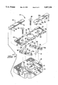
- FIG. 1 is a perspective view of an apparatus according to the invention installed in an applicator frame for punching a slot in flat cable.
- FIG. 2 is a perspective view of a flat cable of the type with which the invention can be used.
- FIG. 3 is an enlarged perspective view of an apparatus according to the invention.
- FIG. 4 is an exploded view of the apparatus according to the invention.
- FIG. 5 is a top view of the apparatus having cable guides in a normal, closed position.
- FIG. 6 is a top view showing the cable guides moved divergently to an open position.
- FIG. 7 is a top view showing the cables guides moved convergently and confining a cable therebetween.
- FIG. 8 is a side view of the apparatus installed in an applicator frame.
- an apparatus for laterally positioning flat cable is shown generally as 10 installed on a representative applicator frame 2 which is operable to perform a punching operation on a flat cable 8.
- the applicator frame 2 includes a base 5 which supports a workpiece such as the cable 8, and a head 7 which houses an actuation cylinder having a reciprocable ram.
- a punch 3 is attached beneath the reciprocable ram.
- Pneumatic or hydraulic pressure is delivered through conduit 4 to the actuation cylinder to drive the ram and the punch 3 downwardly toward die 3a which is constrained on the base 5 in opposition to the punch 3.
- an applicator frame of similar form excepting with a handle 6 to enable manual actuation of the ram and the punching die may be used.
- the flat cable 8 with which the positioning apparatus can be used has a longitudinal cable axis 24 and a cable width which extends in a cable plane between opposite side edges 9, 9a.
- Slots 26 are punched in the cable 8 by an appropriately shaped punch 3 in the applicator frame 2.
- the slots 26 may be longitudinally disposed at any location along the cable axis 24, including at the ends of the cable 8.
- the slots 26 must be laterally positioned in the cable 8 to within a close tolerance, for example, centers of the slots within 0.010 inch of the cable axis 24, regardless of the cable width.
- the positioning apparatus 10 comprises a base 12 which is secured to the base 5 by fasteners (not shown) from the bottom of the base 5.
- the apparatus may optionally comprise a track 42 which is secured to the base 12 by threaded fasteners 46.
- the track 42 extends through a work zone defined by a reciprocation path of the punch 3.
- the track 42 has pairs of opposed shoulders 44 and 45, opposite shoulders of each pair being spaced apart by a distance selected to be greater than the maximum width of the cable 8 which is to be operated on by the applicator frame 2 so that the cable 8 can be loosely received between the opposed shoulders 44 and 45.
- the track 42 is arranged to support the cable 8 and guide it to the work zone when the cable 8 is introduced to the applicator frame 2 from a side thereof, as shown in FIG. 1.
- the track 42 is not a necessary element of the present invention, as the cable 8 may be supported directly on the base 12 in the work zone beneath the punch 3.
- the track 42 has an aperture 64 which, along with a relief 68 in the base 12, permits passage of the punch 3 during piercing of the cable 8 when it is disposed in the work zone.
- the positioning apparatus further comprises a pair of cable guides 16, 16a which are movable with respect to the base 12.
- the cable guides 16, 16a have respective cable guide surfaces 20, 20a which are in opposing relationship.
- Each of the cable guide surfaces 20, 20a is configured complementary to a respective one of the side edges 9, 9a of the cable 8 whereby the cable 8 may be confined therebetween.
- the cable guide surfaces 20, 20a are also preferably angled as shown in the drawings to provide a vertical component of holding force on the cable 8.
- the cable guides 16, 16a are connected by a pivotal linkage which is operable to move the cable guide surfaces 20, 20a convergently and divergently through respective proportional distances on opposite sides of a target plane of convergence 50 which extends perpendicular to a plane of motion of the guide surfaces 20, 20a.
- a target plane of convergence 50 which extends perpendicular to a plane of motion of the guide surfaces 20, 20a.
- the cable axis 24 is accurately aligned parallel to the target plane of convergence 50.
- the linkage is operable to move the guide surfaces 20, 20a convergently and divergently in equal increments, and the target plane 50 is defined centrally between the guide surfaces 20, 20a.
- the linkage comprises a pair of links 52 which reside in recesses 14 of the base 12.
- Each of the links 52 has a pivot post 54 which is pivotally received in a respective aperture 48 defined by the track 42 so as to define a pivot axis for each of the links. If the track 42 is to be omitted from the apparatus, the link pivot posts 54 could be received in respective apertures defined by the base 12.
- the pivot axes extend in a link pivot plane which is parallel to the target plane 50 and, in the illustrated embodiment, coincides therewith.
- Each of the cable guides 16, 16a has a pair of pivot posts 18, 18a, respectively, which are received in respective pairs of apertures 56, 56a defined by ends of the links 52, each pivot post being retained in its respective aperture by a respective retaining ring.
- the apertures 56, 56a are all equidistant from their respective pivot axes defined by the pivot posts 54 of their respective links 52.
- the apparatus 10 may be arranged such that the target plane 50 coincides with the reciprocation axis of the punch 3 in order that the slots 26 may be punched precisely on center with the cable axis 24.
- the apparatus 10 could be arranged such that the target plane 50 is aligned at some distance offset from the reciprocation axis of the punch 3 in order that the slots 26 are punched at a precise location offset from the cable axis 24.
- the guide surfaces 20, 20a extend parallel to each other on opposite sides of the target plane 50. As the links 52 are pivoted on their respective pivot axes defined by the pivot posts 54, the guide surfaces 20, 20a are moved convergently or divergently with respect to the target plane 50 while remaining parallel to each other.
- the apparatus may include biasing means for urging the guide surfaces 20, 20a convergently.
- biasing means may comprise compression springs 36 which have one of their ends confined in pockets 15 defined by the recesses 14 and the other of their ends confined in reliefs 34 defined by the links 52.
- a grip 38 is provided to facilitate movement of the linkage against the bias of the springs 36. By displacing the grip 38 the guide surfaces 20, 20a may be moved sufficiently far apart to permit introduction of a cable 8 therebetween.
- the grip 38 may be, for example, a threaded member which engages in a complementary threaded hole 22 of the cable guide 16a. Alternatively, a displacing force may be applied directly to the cable guides 16, 16a if they are accessible.
- the apparatus may have a stop 72 which has a notched end 74 configured to engage an end of the cable 8 and disposed so as to longitudinally position the end of the cable 8 in the work zone for punching a slot 26 therein.
- the stop 72 is slidable within guide 76 so that the notched end 74 can be withdrawn from the path of the cable 8 to allow passage of the cable 8 through the work zone.
- a pin 78 of the guide 76 is received in a slot 80 of the stop 72 to prevent complete withdrawal of the stop 72 from the apparatus.
- the stop 72 is shown in a withdrawn position in FIG. 7.
- FIG. 5 is a top view illustrating a normal position of the cable guides 16, 16a for the apparatus having biasing springs according to the invention.
- the springs 36 urge the links 52 counterclockwise and thereby urge the guide surfaces 20, 20a relatively together.
- FIG. 6 is a top view illustrating the guide surfaces 20, 20a having been moved relatively apart such as would occur by an operator pushing on the grip 38 in the direction of arrow P.
- the cable guide surfaces 20, 20a are separated by a distance sufficient to permit the operator to insert the cable 8 therebetween.
- the operator then releases the grip 38 to permit the guide surfaces 20, 20a to engage the side edges 9, 9a of the cable 8 due to the bias of the springs 36, is shown in FIG. 7.
- the cable 8 is now confined between the guide surfaces 20, 20a.
- the convergence of the guide surfaces 20, 20a on the target plane 50 causes the cable axis 24 to become aligned in the target plane. Since the target plane 50 has been previously aligned to coincide with the reciprocation axis of the punch 3 as shown in FIG. 8, the slots 26 can be punched precisely in the center of the cable 8.
- the apertures 56 are disposed equidistant from their respective pivot posts 54 at a first distance
- the apertures 56a are disposed equidistant from their respective pivot posts 54 at a second distance different from the first distance, for example, one-half the first distance.
- operation of the linkage moves the guide surfaces 20, 20a convergently such that the guide surface 20 moves incrementally twice as far as the guide surface 20a
- the target plane 50 is defined at a location which is two-thirds of the distance from the guide surface 20 to the guide surface 20a.
- An apparatus has the advantage of providing a simple mechanism for laterally positioning flat cable in a machine, regardless of cable width.
- the apparatus can be aligned in a machine such that any selected location along a width of the cable from a side edge thereof can be aligned with a tool of the machine.
Landscapes
- Life Sciences & Earth Sciences (AREA)
- Forests & Forestry (AREA)
- Engineering & Computer Science (AREA)
- Mechanical Engineering (AREA)
- Processing Of Terminals (AREA)
Abstract
An apparatus for laterally positioning flat cable in a machine for performing an operation on the cable comprises a base and a pair of cable guides which are movable with respect to the base. Each of the cable guides has a cable guide surface configured complementary to a respective cable side edge. The cable guide surfaces are in opposing relationship. A linkage is connected for moving the cable guide surfaces convergently and divergently through respective proportional distances on opposite sides of a target plane of convergence between the cable guide surfaces. When the cable guide surfaces are spaced apart at a distance equal to or greater than the cable width and the cable is introduced between the cable guide surfaces, operation of the linkage so as to move the cable guide surfaces convergently causes the cable to become confined between the cable guide surfaces with the cable longitudinal axis aligned parallel to the target plane.
Description
The invention relates to an apparatus for laterally positioning sections of flat cable having different widths in a machine which performs an operation on the cable sections.
Various types of flat cable are known for use in electrical circuits. Flat cable such as ribbon cable has a plurality of conductors disposed in side-by-side spaced relationship and enclosed in an insulative sheath. Another type of flat cable known as flat power cable is entering commercial use for transmitting electrical power of, for example, 75 amperes nominal. Such flat power cable is about one inch wide and may comprise a single flat conductor such as 0.020 inch thick copper or aluminum with an insulative coating of between 0.004 and 0.008 inch thickness extruded therearound. Also entering commercial acceptance is a dual conductor flat power cable, wherein a pair of co-planar flat conductor strips having insulation extruded therearound define power and return paths for electrical power transmission. The dual conductor strips are spaced approximately 0.100 inch apart, and the insulation which surrounds the strips also fills the gap therebetween.
Electrical connectors are known for terminating dual conductor flat power cable. U.S. Pat. No. 4,915,650 discloses an electrical connector for terminating an end of a dual conductor flat power cable, the terminated end being matable with a corresponding terminated end of another cable, or with a bus bar or power supply, for example. U.S. Pat. No. 5,219,303 discloses a connector for interconnecting a pair of dual flat power cables at a location along a continuous length of at least one of the cables.
The connectors disclosed in the above-referenced patents include terminal assemblies having upper and lower plate sections defining opposed cooperative arrays of conductor engaging members which receive the dual conductor flat power cable therebetween. Prior to terminating a cable, a slot is punched in the cable along its median, thereby removing a short length of the insulative coating between the conductor strips. The terminal assembly is applied to the cable by pressing together the upper and lower plate sections, whereby the conductor engaging members pierce the dual conductor strips of the cable and become interengaged. In a simultaneous operation, central ligatures of the upper and lower plate sections are severed, thereby providing discrete terminals corresponding to the two conductors of the dual power cable so as to enable separate connections to discrete circuits. A dielectric housing is ultimately applied to the terminals to seal out dirt and enable connection to mating terminated cable.
The above-described operation of punching a slot in the cable requires a close tolerance on the position of the slot, for example, the center of the slot to be within 0.010 inch of true position of the center of the cable. If the slot is not positioned within tolerance, the slot will extend unacceptably into one of the dual conductor strips, thereby reducing a width of the strip and preventing secure engagement of the strip by the conductor engaging members of the terminal assembly to be applied.
A machine for punching the slot typically includes a track in which the cable is inserted to position the cable with respect to a punch press. In prior art machines, the track comprises a pair of fixed guides having opposed cable guide surfaces which are spaced apart by a width of the cable so that the cable can be received therebetween. When the cable is centered between the guide surfaces, the median of the cable is aligned with the punching die so that a slot can be punched centrally through the cable. However, there is a manufacturing tolerance on the cable width and, in order for the track to accommodate all cable widths, the guide surfaces are spaced apart by a fixed distance equal to a cable width at the high end of its tolerance range. For example, a typical cable having a width of 1.012 plus or minus 0.013 inch requires the track to have guide surfaces spaced 1.025 inch apart. This results in a problem in that when a cable having a width at the low end of its tolerance range is inserted into the track, the cable has a substantial clearance between the guide surfaces and can not be accurately centered in the track, thereby preventing accurate punching of the slot in the cable. The present invention overcomes this problem by providing a lateral positioning apparatus having an adjustable track width so that cables having different widths may be accurately positioned laterally in a machine for punching a slot in the cable or for performing some other operation on the cable.
The present invention provides an apparatus for laterally positioning a flat cable in a machine for performing an operation on the cable. The cable is of a type which has a width extending between substantially parallel opposite side edges which define a cable plane and a longitudinal cable axis. The apparatus comprises a base and a pair of cable guides which are movable with respect to the base. Each of the cable guides has a cable guide surface configured complementary to a respective one of the cable side edges, the cable guide surfaces being in opposing relationship. A linkage is connected for moving the cable guide surfaces convergently and divergently through respective proportional distances on opposite sides of a target plane of convergence between the cable guide surfaces. When the cable guide surfaces are spaced apart at a distance equal to or greater than the cable width and the cable is introduced between the cable guide surfaces, operation of the linkage so as to move the cable guide surfaces convergently causes the cable to become confined between the cable guide surfaces and the cable axis to become aligned parallel to the target plane.
According to one embodiment of the invention, the linkage includes a pair of links each having a mid-portion pivotally connected to the base about a respective link pivot axis, the link pivot axes extending in a link pivot plane which is parallel to the target plane. Further, the pair of cable guides each have a pair of spaced apart pivotal connections defining a pair of cable guide pivot axes, and each of the pivotal connections couples one of the cable guides to one of the links about its respective cable guide pivot axis. The pairs of cable guide pivot axes are in respective planes on opposite sides of the link pivot plane and parallel thereto. Pivoting of the links about their respective link pivot axes moves the cable guide surfaces convergently and divergently through respective proportional distances.
The foregoing will be more readily apparent upon reading the following description in conjunction with the drawings in which like elements in different figures thereof are identified by the same reference numeral and wherein:
FIG. 1 is a perspective view of an apparatus according to the invention installed in an applicator frame for punching a slot in flat cable.
FIG. 2 is a perspective view of a flat cable of the type with which the invention can be used.
FIG. 3 is an enlarged perspective view of an apparatus according to the invention.
FIG. 4 is an exploded view of the apparatus according to the invention.
FIG. 5 is a top view of the apparatus having cable guides in a normal, closed position.
FIG. 6 is a top view showing the cable guides moved divergently to an open position.
FIG. 7 is a top view showing the cables guides moved convergently and confining a cable therebetween.
FIG. 8 is a side view of the apparatus installed in an applicator frame.
With reference to FIG. 1, an apparatus for laterally positioning flat cable is shown generally as 10 installed on a representative applicator frame 2 which is operable to perform a punching operation on a flat cable 8. The applicator frame 2 includes a base 5 which supports a workpiece such as the cable 8, and a head 7 which houses an actuation cylinder having a reciprocable ram. A punch 3 is attached beneath the reciprocable ram. Pneumatic or hydraulic pressure is delivered through conduit 4 to the actuation cylinder to drive the ram and the punch 3 downwardly toward die 3a which is constrained on the base 5 in opposition to the punch 3. Alternatively, an applicator frame of similar form excepting with a handle 6 to enable manual actuation of the ram and the punching die may be used.
As shown in FIG. 2, the flat cable 8 with which the positioning apparatus can be used has a longitudinal cable axis 24 and a cable width which extends in a cable plane between opposite side edges 9, 9a. Slots 26 are punched in the cable 8 by an appropriately shaped punch 3 in the applicator frame 2. The slots 26 may be longitudinally disposed at any location along the cable axis 24, including at the ends of the cable 8. The slots 26 must be laterally positioned in the cable 8 to within a close tolerance, for example, centers of the slots within 0.010 inch of the cable axis 24, regardless of the cable width.
With reference to FIGS. 1, 3, 4 and 8, the positioning apparatus 10 comprises a base 12 which is secured to the base 5 by fasteners (not shown) from the bottom of the base 5. The apparatus may optionally comprise a track 42 which is secured to the base 12 by threaded fasteners 46. The track 42 extends through a work zone defined by a reciprocation path of the punch 3. The track 42 has pairs of opposed shoulders 44 and 45, opposite shoulders of each pair being spaced apart by a distance selected to be greater than the maximum width of the cable 8 which is to be operated on by the applicator frame 2 so that the cable 8 can be loosely received between the opposed shoulders 44 and 45. The track 42 is arranged to support the cable 8 and guide it to the work zone when the cable 8 is introduced to the applicator frame 2 from a side thereof, as shown in FIG. 1. However, the track 42 is not a necessary element of the present invention, as the cable 8 may be supported directly on the base 12 in the work zone beneath the punch 3. The track 42 has an aperture 64 which, along with a relief 68 in the base 12, permits passage of the punch 3 during piercing of the cable 8 when it is disposed in the work zone.
The positioning apparatus further comprises a pair of cable guides 16, 16a which are movable with respect to the base 12. The cable guides 16, 16a have respective cable guide surfaces 20, 20a which are in opposing relationship. Each of the cable guide surfaces 20, 20a is configured complementary to a respective one of the side edges 9, 9a of the cable 8 whereby the cable 8 may be confined therebetween. The cable guide surfaces 20, 20a are also preferably angled as shown in the drawings to provide a vertical component of holding force on the cable 8.
The cable guides 16, 16a are connected by a pivotal linkage which is operable to move the cable guide surfaces 20, 20a convergently and divergently through respective proportional distances on opposite sides of a target plane of convergence 50 which extends perpendicular to a plane of motion of the guide surfaces 20, 20a. When the cable 8 is confined between the guide surfaces 20, 20a, the cable axis 24 is accurately aligned parallel to the target plane of convergence 50. By positioning the apparatus 10 on the applicator frame 2 such that the target plane of convergence 50 is precisely aligned with respect to the reciprocation axis of the punch 3, the cable axis 24 is accurately aligned laterally with respect to the punch 3.
In the embodiment shown in FIGS. 4-7, the linkage is operable to move the guide surfaces 20, 20a convergently and divergently in equal increments, and the target plane 50 is defined centrally between the guide surfaces 20, 20a. The linkage comprises a pair of links 52 which reside in recesses 14 of the base 12. Each of the links 52 has a pivot post 54 which is pivotally received in a respective aperture 48 defined by the track 42 so as to define a pivot axis for each of the links. If the track 42 is to be omitted from the apparatus, the link pivot posts 54 could be received in respective apertures defined by the base 12. The pivot axes extend in a link pivot plane which is parallel to the target plane 50 and, in the illustrated embodiment, coincides therewith.
Each of the cable guides 16, 16a has a pair of pivot posts 18, 18a, respectively, which are received in respective pairs of apertures 56, 56a defined by ends of the links 52, each pivot post being retained in its respective aperture by a respective retaining ring. In the embodiment shown in FIGS. 4-7, the apertures 56, 56a are all equidistant from their respective pivot axes defined by the pivot posts 54 of their respective links 52. In this case the apparatus 10 may be arranged such that the target plane 50 coincides with the reciprocation axis of the punch 3 in order that the slots 26 may be punched precisely on center with the cable axis 24. Alternatively, the apparatus 10 could be arranged such that the target plane 50 is aligned at some distance offset from the reciprocation axis of the punch 3 in order that the slots 26 are punched at a precise location offset from the cable axis 24. In either case, the guide surfaces 20, 20a extend parallel to each other on opposite sides of the target plane 50. As the links 52 are pivoted on their respective pivot axes defined by the pivot posts 54, the guide surfaces 20, 20a are moved convergently or divergently with respect to the target plane 50 while remaining parallel to each other.
The apparatus may include biasing means for urging the guide surfaces 20, 20a convergently. Such biasing means may comprise compression springs 36 which have one of their ends confined in pockets 15 defined by the recesses 14 and the other of their ends confined in reliefs 34 defined by the links 52.
A grip 38 is provided to facilitate movement of the linkage against the bias of the springs 36. By displacing the grip 38 the guide surfaces 20, 20a may be moved sufficiently far apart to permit introduction of a cable 8 therebetween. The grip 38 may be, for example, a threaded member which engages in a complementary threaded hole 22 of the cable guide 16a. Alternatively, a displacing force may be applied directly to the cable guides 16, 16a if they are accessible.
As best seen in FIGS. 3 and 5, the apparatus may have a stop 72 which has a notched end 74 configured to engage an end of the cable 8 and disposed so as to longitudinally position the end of the cable 8 in the work zone for punching a slot 26 therein. The stop 72 is slidable within guide 76 so that the notched end 74 can be withdrawn from the path of the cable 8 to allow passage of the cable 8 through the work zone. A pin 78 of the guide 76 is received in a slot 80 of the stop 72 to prevent complete withdrawal of the stop 72 from the apparatus. The stop 72 is shown in a withdrawn position in FIG. 7.
FIG. 5 is a top view illustrating a normal position of the cable guides 16, 16a for the apparatus having biasing springs according to the invention. The springs 36 urge the links 52 counterclockwise and thereby urge the guide surfaces 20, 20a relatively together.
FIG. 6 is a top view illustrating the guide surfaces 20, 20a having been moved relatively apart such as would occur by an operator pushing on the grip 38 in the direction of arrow P. In this position, the cable guide surfaces 20, 20a are separated by a distance sufficient to permit the operator to insert the cable 8 therebetween. The operator then releases the grip 38 to permit the guide surfaces 20, 20a to engage the side edges 9, 9a of the cable 8 due to the bias of the springs 36, is shown in FIG. 7. The cable 8 is now confined between the guide surfaces 20, 20a. Further, the convergence of the guide surfaces 20, 20a on the target plane 50 causes the cable axis 24 to become aligned in the target plane. Since the target plane 50 has been previously aligned to coincide with the reciprocation axis of the punch 3 as shown in FIG. 8, the slots 26 can be punched precisely in the center of the cable 8.
In a variation of the above-described embodiment, the apertures 56 are disposed equidistant from their respective pivot posts 54 at a first distance, and the apertures 56a are disposed equidistant from their respective pivot posts 54 at a second distance different from the first distance, for example, one-half the first distance. In this case operation of the linkage moves the guide surfaces 20, 20a convergently such that the guide surface 20 moves incrementally twice as far as the guide surface 20a, and the target plane 50 is defined at a location which is two-thirds of the distance from the guide surface 20 to the guide surface 20a. With the apparatus 10 arranged in the applicator frame such that target plane 50 coincides with the reciprocation axis of the punch 3, confining the cable 8 between the guide surfaces 20, 20a would align the cable such that the cable axis 24 is laterally offset from the reciprocation axis of the punch 3. In this example a slot punched in the cable 8 would be centered along a longitudinal line which is one-third of the cable width inward from the cable side edge 9a. Other proportional distances of the apertures 56 and 56a from their respective pivot posts 54 could be selected to provide an infinite variation in the location of the target plane 50 between the boundaries defined by the guide surfaces 20, 20a, and thus slots could be accurately punched at any location across the cable width.
An apparatus according to the invention has the advantage of providing a simple mechanism for laterally positioning flat cable in a machine, regardless of cable width. The apparatus can be aligned in a machine such that any selected location along a width of the cable from a side edge thereof can be aligned with a tool of the machine.
The invention having been disclosed, a number variations will now become apparent to those skilled in the art. Whereas the invention is intended to encompass the foregoing preferred embodiments as well as a reasonable range of equivalents, reference should be made to the appended claims rather than the foregoing discussion of examples, in order to assess the scope of the invention in which exclusive rights are claimed.
Claims (14)
1. An apparatus for laterally positioning flat cable and performing an operation on the cable, the cable having a longitudinal cable axis and a width extending between opposite side edges which define a cable plane, the apparatus comprising:
a frame including a base;
a pair of cable guides movable with respect to the base, each of the cable guides having a cable guide surface configured complementary to a respective one of the cable side edges, the cable guide surfaces being in opposing relationship;
a linkage connected for moving the cable guide surfaces convergently and divergently through respective proportional distances on opposite sides of a target plane of convergence between the cable guide surfaces;
wherein when the cable guide surfaces are spaced apart at a distance equal to or greater than the cable width and the cable is introduced between the cable guide surfaces, operation of the linkage so as to move the cable guide surfaces convergently causes the cable width to become confined between the cable guide surfaces and the cable axis to become aligned parallel to the target plane;
a tool coupled to the frame and referenced with respect to the target plane; and,
means for guided reciprocation of the tool toward and away from the base such that the tool engages the cable which is confined between the guide surfaces;
whereby the tool engages the cable at a selected location across the width of the cable.
2. The apparatus according to claim 1, wherein the linkage comprises a pair of links each pivotal with respect to the base about a respective link pivot axis, and the link pivot axes extend in a link pivot plane which is parallel to the target plane.
3. The apparatus according to claim 2, wherein the link pivot plane is coincident with the target plane.
4. The apparatus according to claim 2, wherein each of the links has a mid-portion and a pair of opposite end portions, the link pivot axis of each said link is disposed at its respective said mid-portion, and each of said cable guides has a pivotal connection with one of said end portions.
5. The apparatus according to claim 1, further comprising biasing means for urging the cable guide surfaces convergently.
6. The apparatus according to claim 4, wherein the biasing means comprises at least one spring.
7. The apparatus according to claim 1, further comprising a grip connected to one of the cable guides.
8. An apparatus for laterally positioning flat cable and performing an operation on the cable, the cable having a longitudinal cable axis and a width extending between opposite side edges which define a cable plane, the apparatus comprising:
a frame including a base;
a pair of links each having a mid-portion pivotally connected to the base about a respective link pivot axis, the link pivot axes extending in a link pivot plane;
a pair of cable guides each having a pair of spaced apart pivotal connections defining a pair of cable guide pivot axes, each of the pivotal connections coupling one of the cable guides to one of the links about its respective said cable guide pivot axis, the pairs of cable guide pivot axes being in respective planes on opposite sides of the link pivot plane and parallel thereto, each of the cable guides having a cable guide surface configured complementary to a respective one of the cable side edges, the cable guide surfaces being in opposing relationship on opposite sides of a target plane of convergence defined between the cable guide surfaces, the target plane of convergence being parallel to the link pivot plane;
wherein pivoting of the links about their respective link pivot axes moves the cable guide surfaces convergently and divergently through respective proportional distances, such that when the cable guide surfaces are spaced apart at a distance equal to or greater than the cable width and the cable is introduced between the cable guide surfaces, pivoting of the links so as to urge the cable guide surfaces convergently causes the cable width to become confined between the cable guide surfaces and the cable axis to become aligned parallel to the target plane;
a tool coupled to the frame and referenced with respect to the target plane; and,
means for guided reciprocation of the tool toward and away from the base such that the tool engages the cable which is confined between the guide surfaces;
whereby the tool engages the cable at a selected location across the width of the cable.
9. The apparatus according to claim 8, wherein the link pivot plane is coincident with the target plane.
10. The apparatus according to claim 8, further comprising biasing means for urging the cable guide surfaces convergently.
11. The apparatus according to claim 10, wherein the biasing means comprises at least one spring.
12. The apparatus according to claim 8, further comprising a grip connected to one of the cable guides.
13. The apparatus according to claim 1, wherein the tool is a punch which impacts the cable during the reciprocation, whereby the punch drives a hole through the cable at a selected location across the width of the cable.
14. The apparatus according to claim 8, wherein the tool is a punch which impacts the cable during the reciprocation, whereby the punch drives a hole through the cable at a selected location across the width of the cable.
Priority Applications (1)
| Application Number | Priority Date | Filing Date | Title |
|---|---|---|---|
| US08/159,352 US5417134A (en) | 1993-11-30 | 1993-11-30 | Apparatus for laterally positioning flat cable |
Applications Claiming Priority (1)
| Application Number | Priority Date | Filing Date | Title |
|---|---|---|---|
| US08/159,352 US5417134A (en) | 1993-11-30 | 1993-11-30 | Apparatus for laterally positioning flat cable |
Publications (1)
| Publication Number | Publication Date |
|---|---|
| US5417134A true US5417134A (en) | 1995-05-23 |
Family
ID=22572223
Family Applications (1)
| Application Number | Title | Priority Date | Filing Date |
|---|---|---|---|
| US08/159,352 Expired - Fee Related US5417134A (en) | 1993-11-30 | 1993-11-30 | Apparatus for laterally positioning flat cable |
Country Status (1)
| Country | Link |
|---|---|
| US (1) | US5417134A (en) |
Cited By (7)
| Publication number | Priority date | Publication date | Assignee | Title |
|---|---|---|---|---|
| FR2787375A1 (en) * | 1998-12-21 | 2000-06-23 | Axoral | METHOD OF PUNCHING A FLAT CABLE |
| WO2000061337A1 (en) * | 1999-04-09 | 2000-10-19 | Sds Usa, Inc. | An apparatus for processing a rotary cutting blade |
| US20030084763A1 (en) * | 2001-11-02 | 2003-05-08 | Strand Aaron L | Punch device for creating a guide notch in a polymeric fastener attached to a plastic package |
| US20030115757A1 (en) * | 2001-10-26 | 2003-06-26 | Claudio Meisser | Method and equipment for stripping a flat cable |
| KR100917896B1 (en) | 2007-12-31 | 2009-09-17 | 한국단자공업 주식회사 | Basic material Guide position control structure for die |
| US20110185874A1 (en) * | 2010-01-29 | 2011-08-04 | Jason Blair | Punch Press |
| CN102990710A (en) * | 2012-10-29 | 2013-03-27 | 茅惠杰 | Improved punching structure |
Citations (8)
| Publication number | Priority date | Publication date | Assignee | Title |
|---|---|---|---|---|
| US1117024A (en) * | 1913-04-28 | 1914-11-10 | Josiah B Gathright | Wrench. |
| US1423933A (en) * | 1921-07-06 | 1922-07-25 | William C Heatlie | Clamp |
| US2241021A (en) * | 1939-07-19 | 1941-05-06 | Riebe Johannes | Clamping device |
| US2756822A (en) * | 1952-03-10 | 1956-07-31 | Tucker Smith G | Card perforating device employing a punch movable laterally and longitudinally of the card |
| US4252303A (en) * | 1978-12-22 | 1981-02-24 | Yoshida Kogyo K.K. | Self-alignable holder for a row of slide fastener coupling elements |
| US4452118A (en) * | 1982-12-06 | 1984-06-05 | Reinhard Muller | Shake resaw machine |
| US4476757A (en) * | 1982-09-02 | 1984-10-16 | Shopsmith, Inc. | Adjustable featherboard |
| US4480181A (en) * | 1982-12-23 | 1984-10-30 | Fisher Charles R | Card capture device |
-
1993
- 1993-11-30 US US08/159,352 patent/US5417134A/en not_active Expired - Fee Related
Patent Citations (8)
| Publication number | Priority date | Publication date | Assignee | Title |
|---|---|---|---|---|
| US1117024A (en) * | 1913-04-28 | 1914-11-10 | Josiah B Gathright | Wrench. |
| US1423933A (en) * | 1921-07-06 | 1922-07-25 | William C Heatlie | Clamp |
| US2241021A (en) * | 1939-07-19 | 1941-05-06 | Riebe Johannes | Clamping device |
| US2756822A (en) * | 1952-03-10 | 1956-07-31 | Tucker Smith G | Card perforating device employing a punch movable laterally and longitudinally of the card |
| US4252303A (en) * | 1978-12-22 | 1981-02-24 | Yoshida Kogyo K.K. | Self-alignable holder for a row of slide fastener coupling elements |
| US4476757A (en) * | 1982-09-02 | 1984-10-16 | Shopsmith, Inc. | Adjustable featherboard |
| US4452118A (en) * | 1982-12-06 | 1984-06-05 | Reinhard Muller | Shake resaw machine |
| US4480181A (en) * | 1982-12-23 | 1984-10-30 | Fisher Charles R | Card capture device |
Cited By (10)
| Publication number | Priority date | Publication date | Assignee | Title |
|---|---|---|---|---|
| FR2787375A1 (en) * | 1998-12-21 | 2000-06-23 | Axoral | METHOD OF PUNCHING A FLAT CABLE |
| EP1013384A1 (en) * | 1998-12-21 | 2000-06-28 | Axoral | Method of punching a flat cable |
| US6400397B1 (en) | 1998-12-21 | 2002-06-04 | Axoral | Method of punching a flat cable |
| WO2000061337A1 (en) * | 1999-04-09 | 2000-10-19 | Sds Usa, Inc. | An apparatus for processing a rotary cutting blade |
| US20030115757A1 (en) * | 2001-10-26 | 2003-06-26 | Claudio Meisser | Method and equipment for stripping a flat cable |
| US20030084763A1 (en) * | 2001-11-02 | 2003-05-08 | Strand Aaron L | Punch device for creating a guide notch in a polymeric fastener attached to a plastic package |
| US7100487B2 (en) * | 2001-11-02 | 2006-09-05 | Pactiv Corporation | Punch device for creating a guide notch in a polymeric fastener attached to a plastic package |
| KR100917896B1 (en) | 2007-12-31 | 2009-09-17 | 한국단자공업 주식회사 | Basic material Guide position control structure for die |
| US20110185874A1 (en) * | 2010-01-29 | 2011-08-04 | Jason Blair | Punch Press |
| CN102990710A (en) * | 2012-10-29 | 2013-03-27 | 茅惠杰 | Improved punching structure |
Similar Documents
| Publication | Publication Date | Title |
|---|---|---|
| US4020540A (en) | Applicator tool | |
| EP0034000B1 (en) | Terminal for circuit board | |
| CA1061992A (en) | Wire positioning and insertion apparatus | |
| EP0034433B1 (en) | An electrical connector, a method of gang terminating electrical conductors and apparatus for carrying out the method | |
| US3845535A (en) | Apparatus for connecting conductors to contact terminals in an electrical connector | |
| US3886641A (en) | Apparatus for inserting wires into terminals in an electrical connector | |
| US4742746A (en) | Reworking and sizing of flat conductor cable | |
| US4625386A (en) | Combination tool | |
| CA1280875C (en) | Terminal strip applicator | |
| DE10229873A1 (en) | Piercing connection, as well as device and method for crimping a piercing connection | |
| US4048710A (en) | Conductor terminating apparatus | |
| US4979291A (en) | Apparatus and method of terminating a wire to a two part insulated terminal | |
| US3393438A (en) | Crimping tool | |
| US4534107A (en) | Wire insertion and terminal crimping tool | |
| EP0638958B1 (en) | Electrical connector for high density ribbon cable | |
| US5402561A (en) | Crimping tool having angularly offset crimping dies | |
| US5771574A (en) | Apparatus for manufacturing pressure-welded electrical harnesses and a method thereof | |
| US5417134A (en) | Apparatus for laterally positioning flat cable | |
| US3938246A (en) | Method and apparatus for attaching multi-conductor flat cable to an electrical connector | |
| EP0004779B1 (en) | Apparatus for applying electrical connectors to cables | |
| EP0124581B1 (en) | Flat cable connector and terminator therefor | |
| US5457876A (en) | Conductor guide mechanism in a tool for terminating conductors of a cable to a connector | |
| US4369819A (en) | Lead wire forming apparatus for electric parts | |
| US4488353A (en) | Termination tooling for applying connectors to flat cable | |
| US4412566A (en) | Apparatus for transposing a pair of parallel and adjacent conductors into a vertical relationship |
Legal Events
| Date | Code | Title | Description |
|---|---|---|---|
| AS | Assignment |
Owner name: WHITAKER CORPORATION, THE, DELAWARE Free format text: ASSIGNMENT OF ASSIGNORS INTEREST;ASSIGNOR:FITZ, CHARLES E. JR.;REEL/FRAME:006787/0825 Effective date: 19931124 |
|
| FPAY | Fee payment |
Year of fee payment: 4 |
|
| REMI | Maintenance fee reminder mailed | ||
| LAPS | Lapse for failure to pay maintenance fees | ||
| STCH | Information on status: patent discontinuation |
Free format text: PATENT EXPIRED DUE TO NONPAYMENT OF MAINTENANCE FEES UNDER 37 CFR 1.362 |
|
| FP | Lapsed due to failure to pay maintenance fee |
Effective date: 20030523 |