EP0482705A2 - Schaltungsanordnung - Google Patents
Schaltungsanordnung Download PDFInfo
- Publication number
- EP0482705A2 EP0482705A2 EP91202697A EP91202697A EP0482705A2 EP 0482705 A2 EP0482705 A2 EP 0482705A2 EP 91202697 A EP91202697 A EP 91202697A EP 91202697 A EP91202697 A EP 91202697A EP 0482705 A2 EP0482705 A2 EP 0482705A2
- Authority
- EP
- European Patent Office
- Prior art keywords
- lamp
- signal
- frequency
- conducting
- circuit
- Prior art date
- Legal status (The legal status is an assumption and is not a legal conclusion. Google has not performed a legal analysis and makes no representation as to the accuracy of the status listed.)
- Granted
Links
Images

Classifications
-
- H—ELECTRICITY
- H05—ELECTRIC TECHNIQUES NOT OTHERWISE PROVIDED FOR
- H05B—ELECTRIC HEATING; ELECTRIC LIGHT SOURCES NOT OTHERWISE PROVIDED FOR; CIRCUIT ARRANGEMENTS FOR ELECTRIC LIGHT SOURCES, IN GENERAL
- H05B41/00—Circuit arrangements or apparatus for igniting or operating discharge lamps
- H05B41/14—Circuit arrangements
- H05B41/36—Controlling
- H05B41/38—Controlling the intensity of light
- H05B41/39—Controlling the intensity of light continuously
- H05B41/392—Controlling the intensity of light continuously using semiconductor devices, e.g. thyristor
- H05B41/3921—Controlling the intensity of light continuously using semiconductor devices, e.g. thyristor with possibility of light intensity variations
- H05B41/3925—Controlling the intensity of light continuously using semiconductor devices, e.g. thyristor with possibility of light intensity variations by frequency variation
Definitions
- the circuit arrangement described therein controls the amplitude of the lamp current of a discharge lamp operated on the circuit arrangement at a substantially constant level.
- control signal is also dependent on the lamp voltage, it is possible to control an average value of the power consumed by the lamp (this average value will be called the lamp power hereinafter) at a substantially constant value for various types of discharge lamps and to render it substantially independent of factors such as variations in the supply voltage or fluctuations in the ambient temperature.
- control signal is dependent on a desired average value of the power consumed by the discharge lamp, there is a possibility of dimming the discharge lamp through adjustment of the desired average value of the power consumed by the discharge lamp.
- the value of the frequency f is adapted in such a way that the lamp power is substantially equal to the desired power.
- Lamp power values situated within the range over which the lamp power increases as a function of the frequency cannot be adjusted: an oscillation of the lamp power is found to take place between the desired value and a second value of the lamp power belonging to the relevant value of the frequency f. Besides a relation between lamp power and the frequency f within a certain lamp power range which is not unequivocal, there is also found to exist a relation between the average lamp current and the frequency f within a certain range of the average lamp current which is not unequivocal for such lamps. The result is that some values of the average lamp current cannot be adjusted, while for some settings oscillations in the lamp current amplitude are found to occur.
- control signal is in addition dependent on a signal S which is a measure for comparatively quick changes in the power consumed by the discharge lamp.
- control signal depends also on comparatively quick changes in the lamp power.
- the signal S may be derived from the lamp current, but also from other parameters such as the lamp voltage or the phase difference between the voltage across and the current through the load branch.
- Fig. 1 is a diagrammatic representation of the build-up of a circuit arrangement according to the invention
- B is a load branch provided with lamp connection terminals K1 and K2.
- a lamp La can be connected to the lamp connection terminals K1 and K2.
- D is a DC-AC converter provided with input terminals 1 and 2 and with a branch A which comprises at least one switching element for generating a current of alternating polarity through the load branch B by being alternately conducting and non-conducting with frequency f.
- Branch A is for this purpose coupled to load branch B.
- E is a drive circuit coupled to branch A for rendering the switching element in branch A alternately conducting and non-conducting with frequency f.
- Control circuit C is a control circuit for generating a control signal which is to influence the frequency f, which control signal is dependent on the lamp current as well as on a signal S which is a measure for comparatively quick changes in the power consumed by the discharge lamp.
- Control circuit C is for this purpose coupled to load branch B and drive circuit E.
- the operation of the circuit arrangement shown in Fig. 1 is as follows.
- the drive circuit E renders the switching element in branch A alternately conducting and non-conducting with frequency f.
- a current whose polarity changes with frequency f flows through the load branch B.
- the control circuit generates a control signal which is to influence the frequency f and which is dependent on the lamp current as well as on a signal S which is a measure for comparatively quick changes in the power consumed by the discharge lamp. Since the control signal is also dependent on signal S, there is an unequivocal relation between the control signal and the lamp power over substantially the entire range of this lamp power, irrespective of the type and power rating of the discharge lamp La. This renders it possible to set the lamp power for any desired value.
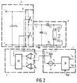
- branch A is formed by a series circuit of switching elements T1 and T2.
- Branch A together with input terminals 1 and 2 and capacitor C4 forms a DC-AC converter.
- Coil L, capacitors C2 and C3, lamp connection terminals K1 and K2, and sensor resistor Rs constitute load branch B.
- a discharge lamp La can be connected to the lamp connection terminals.
- Comparators I and II and circuit element III constitute drive signal generator E.
- Control circuit C in this embodiment consists of current source S1, capacitor C1 and circuit element IV.
- the circuit arrangement is built up as follows.
- a first end of branch A is connected to input terminal 1 and a further end of branch A is connected to input terminal 2.
- Input terminal 2 is also earthed.
- Input terminals 1 and 2 are interconnected by capacitor C4.
- Switching element T2 of branch A is shunted by a series circuit of coil L and capacitor C3.
- Capacitor C3 is shunted by a series circuit of capacitor C2, lamp connection terminal K1, lamp connection terminal K2 and sensor resistor Rs.
- Circuit element IV is coupled to the lamp in a manner not shown in the Figure.
- a further side of the capacitor C1 is connected to a side of the sensor resistor Rs remote from input terminal 2. Since the lamp current flows through Rs, the voltage across Rs is proportional to the instantaneous value of the lamp current: the voltage across Rs in this embodiment forms the signal S.
- the potential at the first side of the capacitor C1 is equal to the sum of the voltage across the resistor Rs and the voltage across the capacitor C1, and in this embodiment acts as the control signal.
- the first side of capacitor C1 is connected to an input of a first comparator and an input of a further comparator.
- a substantially constant voltage V1 is present at a further input of the first comparator.
- a substantially constant voltage V2 is present at a further input of the further comparator. Voltage V2 is higher than voltage V1.
- An output of the first comparator is connected to an input of circuit element III.
- An output of the further comparator is connected to a further input of circuit element III.
- a first output of circuit element III is connected to an input of the current source. It is realised in this way that the current generated by the current source reverses its direction when the control signal is lower than the potential V1 or higher than the potential V2. As a result, the control signal is a substantially triangular voltage.
- the first output of circuit element III is also coupled to the switching element T1.
- a further output of circuit element III is coupled to switching element T2. In a stationary operating condition, the drive circuit E renders the switching elements alternately conducting with frequency f.
- a substantially square-wave voltage with frequency f is present between ends of the load branch, and a current flows through the load branch whose polarity changes with frequency f.
- the frequency f is substantially equal to the frequency of the control signal.
- the frequency of the control signal depends on the potential Vref which is a measure for the desired lamp power and the actual lamp power. If the control signal should be exclusively dependent on the desired and the actual lamp powers, the relation between the control signal and the lamp power would not be unequivocal over a certain lamp power range for some lamps, for example, compact fluorescent lamps. As a result, an oscillation of the actual lamp power occurs in some settings of the desired lamp power by means of such a control signal.
- the control signal is also dependent on comparatively quick changes in the lamp power, so that the relation between the control signal and the lamp power is unequivocal over the entire desired adjustment range of the lamp power, and substantially all desired lamp powers can be realised without oscillations occurring, irrespective of the type of discharge lamp used. Since only the resistor Rs is required for generating the signal S in this embodiment, the means for generating the signal S in this embodiment are simple and inexpensive.
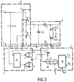
- the circuit arrangement shown in Fig. 3 is for a major part identical to the circuit arrangement shown in Fig. 1.
- the further side of capacitor C1 in the circuit arrangement shown in Fig. 2 is earthed, while moreover an adder device is present between the output of circuit element IV and current source S1 for increasing the signal R by a signal S which is a measure for comparatively quick changes in the lamp power.
- the control signal in this embodiment is the substantially triangular voltage across capacitor C1, and the frequency f is substantially equal to the frequency of the control signal. Since the strength of the current supplied by the current source also depends on signal S, the control signal is equally dependent on the signal S. For this embodiment of a circuit arrangement according to the invention, too, an unequivocal relation between the control signal and the lamp power is found over the entire desired adjustment range of the lamp power, irrespective of the type of the discharge lamp used.
- resistor Rs conducts the lamp current during the operation of the circuit section, while one end of the resistor Rs is earthed.
- a voltage U3 is present at input terminal 3, which is connected to a further end of the resistor Rs, which voltage U3 is proportional to the instantaneous value of the lamp current.
- This voltage is shown as a function of time in Fig. 4b.
- Input terminal 3 is connected to an input of an amplifier V for amplifying this voltage.
- An output of this amplifier is connected to an input of rectifier means for rectifying the amplified voltage.
- An output of the rectifier means is connected to an input of a low-pass filter VII.
Applications Claiming Priority (2)
| Application Number | Priority Date | Filing Date | Title |
|---|---|---|---|
| NL9002332 | 1990-10-25 | ||
| NL9002332 | 1990-10-25 |
Publications (3)
| Publication Number | Publication Date |
|---|---|
| EP0482705A2 true EP0482705A2 (de) | 1992-04-29 |
| EP0482705A3 EP0482705A3 (en) | 1992-11-19 |
| EP0482705B1 EP0482705B1 (de) | 1996-01-03 |
Family
ID=19857879
Family Applications (1)
| Application Number | Title | Priority Date | Filing Date |
|---|---|---|---|
| EP91202697A Expired - Lifetime EP0482705B1 (de) | 1990-10-25 | 1991-10-17 | Schaltungsanordnung |
Country Status (8)
| Country | Link |
|---|---|
| US (1) | US5198726A (de) |
| EP (1) | EP0482705B1 (de) |
| JP (1) | JPH04264397A (de) |
| KR (1) | KR920008893A (de) |
| AT (1) | ATE132686T1 (de) |
| DE (1) | DE69116081T2 (de) |
| FI (1) | FI914970A (de) |
| HU (1) | HU212521B (de) |
Cited By (7)
| Publication number | Priority date | Publication date | Assignee | Title |
|---|---|---|---|---|
| EP0641149A1 (de) * | 1993-08-23 | 1995-03-01 | Koninklijke Philips Electronics N.V. | Leistungssteuerung eines Vorschaltgerätes für eine Entladungslampe |
| EP0708579A1 (de) * | 1994-10-19 | 1996-04-24 | Patent-Treuhand-Gesellschaft für elektrische Glühlampen mbH | Verfahren zum Betrieb einer Entladungslampe und Schaltungsanordnung zum Betrieb einer Entladungslampe |
| US5742134A (en) * | 1996-05-03 | 1998-04-21 | Philips Electronics North America Corp. | Inverter driving scheme |
| EP1148768A2 (de) * | 2000-04-14 | 2001-10-24 | Patent-Treuhand-Gesellschaft für elektrische Glühlampen mbH | Stabilisierung des Betriebs von Gasentladungslampen |
| WO2008029344A1 (en) * | 2006-09-07 | 2008-03-13 | Koninklijke Philips Electronics N.V. | Lamp driver circuit and method for driving a discharge lamp |
| CN102640572A (zh) * | 2009-12-08 | 2012-08-15 | 皇家飞利浦电子股份有限公司 | 用于驱动荧光灯的方法和设备 |
| WO2015158921A1 (de) * | 2014-04-19 | 2015-10-22 | Iie Gmbh & Co. Kg | Vorrichtung und verfahren zum betreiben eines lichterzeugers |
Families Citing this family (23)
| Publication number | Priority date | Publication date | Assignee | Title |
|---|---|---|---|---|
| US5373217A (en) * | 1993-03-24 | 1994-12-13 | Osram Sylvania Inc. | Method and circuit for enhancing stability during dimming of electrodeless hid lamp |
| US5422545A (en) * | 1993-08-19 | 1995-06-06 | Tek-Tron Enterprises, Inc. | Closed loop feedback control circuits for gas discharge lamps |
| US5744913A (en) * | 1994-03-25 | 1998-04-28 | Pacific Scientific Company | Fluorescent lamp apparatus with integral dimming control |
| US5686799A (en) * | 1994-03-25 | 1997-11-11 | Pacific Scientific Company | Ballast circuit for compact fluorescent lamp |
| US5691606A (en) * | 1994-09-30 | 1997-11-25 | Pacific Scientific Company | Ballast circuit for fluorescent lamp |
| US5821699A (en) * | 1994-09-30 | 1998-10-13 | Pacific Scientific | Ballast circuit for fluorescent lamps |
| US6037722A (en) * | 1994-09-30 | 2000-03-14 | Pacific Scientific | Dimmable ballast apparatus and method for controlling power delivered to a fluorescent lamp |
| US5596247A (en) * | 1994-10-03 | 1997-01-21 | Pacific Scientific Company | Compact dimmable fluorescent lamps with central dimming ring |
| CN1124778C (zh) * | 1995-06-29 | 2003-10-15 | 皇家菲利浦电子有限公司 | 电路配置 |
| US5751118A (en) * | 1995-07-07 | 1998-05-12 | Magnetek | Universal input dimmer interface |
| TW381409B (en) * | 1996-03-14 | 2000-02-01 | Mitsubishi Electric Corp | Discharging lamp lighting device |
| US5925986A (en) * | 1996-05-09 | 1999-07-20 | Pacific Scientific Company | Method and apparatus for controlling power delivered to a fluorescent lamp |
| US5990634A (en) * | 1996-05-31 | 1999-11-23 | Logic Laboratories, Inc. | Dynamic range dimmer for gas discharge lamps |
| DE69736273T2 (de) * | 1996-09-11 | 2007-07-05 | Koninklijke Philips Electronics N.V. | Schaltungsanordnung |
| US5866993A (en) * | 1996-11-14 | 1999-02-02 | Pacific Scientific Company | Three-way dimming ballast circuit with passive power factor correction |
| JP3858317B2 (ja) * | 1996-11-29 | 2006-12-13 | 東芝ライテック株式会社 | 放電灯点灯装置及び照明装置 |
| US5798617A (en) * | 1996-12-18 | 1998-08-25 | Pacific Scientific Company | Magnetic feedback ballast circuit for fluorescent lamp |
| KR100350685B1 (ko) * | 1999-11-11 | 2003-01-24 | 송정식 | 1회용 혈관 수지침 |
| US6448713B1 (en) * | 2000-12-07 | 2002-09-10 | General Electric Company | Sensing and control for dimmable electronic ballast |
| US6639369B2 (en) | 2001-03-22 | 2003-10-28 | International Rectifier Corporation | Electronic dimmable ballast for high intensity discharge lamp |
| CN1463569A (zh) * | 2001-05-31 | 2003-12-24 | 皇家菲利浦电子有限公司 | 控制供给放电灯的功率的功率控制设备、装置和方法 |
| US6969955B2 (en) * | 2004-01-29 | 2005-11-29 | Axis Technologies, Inc. | Method and apparatus for dimming control of electronic ballasts |
| US20070127179A1 (en) * | 2005-12-05 | 2007-06-07 | Ludjin William R | Burnout protection switch |
Citations (4)
| Publication number | Priority date | Publication date | Assignee | Title |
|---|---|---|---|---|
| EP0059064B1 (de) * | 1981-02-21 | 1985-10-02 | THORN EMI plc | Anordnung zum Starten und Betreiben von Lampen |
| EP0178852A1 (de) * | 1984-10-16 | 1986-04-23 | ADVANCE TRANSFORMER CO. (a Division of Philips Electronics North America Corporation) | Elektronisches Vorschaltgerät für Leuchtstofflampen |
| EP0311424A2 (de) * | 1987-10-08 | 1989-04-12 | ADVANCE TRANSFORMER CO. (a Division of Philips Electronics North America Corporation) | Hochfrequenzvorschaltgerät für Entladungsgaslampen |
| EP0338109A1 (de) * | 1988-04-20 | 1989-10-25 | Zumtobel Aktiengesellschaft | Vorschaltgerät für eine Entladungslampe |
Family Cites Families (7)
| Publication number | Priority date | Publication date | Assignee | Title |
|---|---|---|---|---|
| US3913002A (en) * | 1974-01-02 | 1975-10-14 | Gen Electric | Power circuits for obtaining a high power factor electronically |
| US4894587A (en) * | 1984-08-17 | 1990-01-16 | Lutron Electronics Co., Inc. | High frequency gas discharge lamp dimming ballast |
| US4906901A (en) * | 1988-08-29 | 1990-03-06 | Gardenamerica Corporation | Power supply for outdoor lighting systems using high frequency |
| US5097181A (en) * | 1989-09-29 | 1992-03-17 | Toshiba Lighting & Technology Corporation | Discharge lamp lighting device having level shift control function |
| EP0422255B1 (de) * | 1989-10-09 | 1994-03-02 | Siemens Aktiengesellschaft | Elektronisches Vorschaltgerät |
| US5075602A (en) * | 1989-11-29 | 1991-12-24 | U.S. Philips Corporation | Discharge lamp control circuit arrangement |
| DE4015397A1 (de) * | 1990-05-14 | 1991-11-21 | Hella Kg Hueck & Co | Schaltungsanordnung zum zuenden und betreiben einer hochdruckgasentladungslampe in kraftfahrzeugen |
-
1991
- 1991-09-30 US US07/770,059 patent/US5198726A/en not_active Expired - Fee Related
- 1991-10-17 AT AT91202697T patent/ATE132686T1/de active
- 1991-10-17 DE DE69116081T patent/DE69116081T2/de not_active Expired - Fee Related
- 1991-10-17 EP EP91202697A patent/EP0482705B1/de not_active Expired - Lifetime
- 1991-10-22 HU HU913330A patent/HU212521B/hu not_active IP Right Cessation
- 1991-10-22 KR KR1019910018567A patent/KR920008893A/ko active IP Right Grant
- 1991-10-22 FI FI914970A patent/FI914970A/fi unknown
- 1991-10-25 JP JP3279680A patent/JPH04264397A/ja active Pending
Patent Citations (4)
| Publication number | Priority date | Publication date | Assignee | Title |
|---|---|---|---|---|
| EP0059064B1 (de) * | 1981-02-21 | 1985-10-02 | THORN EMI plc | Anordnung zum Starten und Betreiben von Lampen |
| EP0178852A1 (de) * | 1984-10-16 | 1986-04-23 | ADVANCE TRANSFORMER CO. (a Division of Philips Electronics North America Corporation) | Elektronisches Vorschaltgerät für Leuchtstofflampen |
| EP0311424A2 (de) * | 1987-10-08 | 1989-04-12 | ADVANCE TRANSFORMER CO. (a Division of Philips Electronics North America Corporation) | Hochfrequenzvorschaltgerät für Entladungsgaslampen |
| EP0338109A1 (de) * | 1988-04-20 | 1989-10-25 | Zumtobel Aktiengesellschaft | Vorschaltgerät für eine Entladungslampe |
Cited By (12)
| Publication number | Priority date | Publication date | Assignee | Title |
|---|---|---|---|---|
| EP0641149A1 (de) * | 1993-08-23 | 1995-03-01 | Koninklijke Philips Electronics N.V. | Leistungssteuerung eines Vorschaltgerätes für eine Entladungslampe |
| BE1007458A3 (nl) * | 1993-08-23 | 1995-07-04 | Philips Electronics Nv | Schakelinrichting. |
| EP0708579A1 (de) * | 1994-10-19 | 1996-04-24 | Patent-Treuhand-Gesellschaft für elektrische Glühlampen mbH | Verfahren zum Betrieb einer Entladungslampe und Schaltungsanordnung zum Betrieb einer Entladungslampe |
| US5680015A (en) * | 1994-10-19 | 1997-10-21 | Patent-Treuhand-Gesellschaft F. Elektrische Gluehlampen Mbh | Method to operate a discharge lamp, and circuit arrangement for operation of the discharge lamp |
| CN1048142C (zh) * | 1994-10-19 | 2000-01-05 | 电灯专利信托有限公司 | 使放电灯工作的方法及其电路结构 |
| US5742134A (en) * | 1996-05-03 | 1998-04-21 | Philips Electronics North America Corp. | Inverter driving scheme |
| EP1148768A2 (de) * | 2000-04-14 | 2001-10-24 | Patent-Treuhand-Gesellschaft für elektrische Glühlampen mbH | Stabilisierung des Betriebs von Gasentladungslampen |
| EP1148768A3 (de) * | 2000-04-14 | 2004-01-28 | Patent-Treuhand-Gesellschaft für elektrische Glühlampen mbH | Stabilisierung des Betriebs von Gasentladungslampen |
| WO2008029344A1 (en) * | 2006-09-07 | 2008-03-13 | Koninklijke Philips Electronics N.V. | Lamp driver circuit and method for driving a discharge lamp |
| US7990076B2 (en) | 2006-09-07 | 2011-08-02 | Koninklijke Philips Electronics N.V. | Lamp driver circuit and method for driving a discharge lamp |
| CN102640572A (zh) * | 2009-12-08 | 2012-08-15 | 皇家飞利浦电子股份有限公司 | 用于驱动荧光灯的方法和设备 |
| WO2015158921A1 (de) * | 2014-04-19 | 2015-10-22 | Iie Gmbh & Co. Kg | Vorrichtung und verfahren zum betreiben eines lichterzeugers |
Also Published As
| Publication number | Publication date |
|---|---|
| EP0482705B1 (de) | 1996-01-03 |
| HU913330D0 (en) | 1992-01-28 |
| KR920008893A (ko) | 1992-05-28 |
| DE69116081T2 (de) | 1996-08-08 |
| ATE132686T1 (de) | 1996-01-15 |
| JPH04264397A (ja) | 1992-09-21 |
| HUT59524A (en) | 1992-05-28 |
| FI914970A (fi) | 1992-04-26 |
| EP0482705A3 (en) | 1992-11-19 |
| US5198726A (en) | 1993-03-30 |
| DE69116081D1 (de) | 1996-02-15 |
| HU212521B (en) | 1996-07-29 |
| FI914970A0 (fi) | 1991-10-22 |
Similar Documents
| Publication | Publication Date | Title |
|---|---|---|
| EP0482705B1 (de) | Schaltungsanordnung | |
| US4952848A (en) | Signal generating circuit for ballast control of discharge lamps | |
| US4471269A (en) | Circuit arrangement for operating a high-pressure gas discharge lamp | |
| CA1151721A (en) | Power supply for a high density discharge or fluorescent lamp | |
| EP0715779B1 (de) | Schaltungsganordnung | |
| JPS62135265A (ja) | 直流電圧形成回路 | |
| EP0430358A1 (de) | Schaltanordnung | |
| US5075602A (en) | Discharge lamp control circuit arrangement | |
| US5172033A (en) | Discharge lamp operating inverter circuit with electric dimmer utilizing frequency control of the inverter | |
| US5844380A (en) | Circuit arrangement for ingniting and supplying power to a lamp | |
| US5670849A (en) | Circuit arrangement | |
| US4731722A (en) | Low AC harmonic DC power supply | |
| US6091209A (en) | Piezoelectric transformer discharge lamp operating circuit with duty cycle dimming circuit | |
| US5400241A (en) | High frequency discharge lamp | |
| EP1342393B1 (de) | Digitales vorschaltgerät | |
| EP0599405B1 (de) | Vorschaltgerät mit niedrigem Oberwellengehalt für eine Entladungslampe | |
| EP0860097B1 (de) | Schaltungsanordnung | |
| US5861768A (en) | Resolver exciter having a simple power source unit | |
| JP3724594B2 (ja) | 放電灯点灯装置 | |
| EP0734640B1 (de) | Schaltung für eine lampe bestehend aus 2 armen die mit der lampe verbunden sind | |
| GB2093613A (en) | D.C. power supply | |
| JPH06338397A (ja) | 放電灯点灯装置および照明装置 | |
| US6727663B2 (en) | Circuit arrangement for feeding a load | |
| US20060267520A1 (en) | Total harmonic distortion reduction for electronic dimming ballast | |
| EP0971566A2 (de) | Adaptereinrichtung zur Verbindung von Lasten mit einer geregelten Stromquelle |
Legal Events
| Date | Code | Title | Description |
|---|---|---|---|
| PUAI | Public reference made under article 153(3) epc to a published international application that has entered the european phase |
Free format text: ORIGINAL CODE: 0009012 |
|
| AK | Designated contracting states |
Kind code of ref document: A2 Designated state(s): AT BE CH DE FR GB IT LI NL |
|
| PUAL | Search report despatched |
Free format text: ORIGINAL CODE: 0009013 |
|
| AK | Designated contracting states |
Kind code of ref document: A3 Designated state(s): AT BE CH DE FR GB IT LI NL |
|
| 17P | Request for examination filed |
Effective date: 19930426 |
|
| 17Q | First examination report despatched |
Effective date: 19950111 |
|
| GRAA | (expected) grant |
Free format text: ORIGINAL CODE: 0009210 |
|
| AK | Designated contracting states |
Kind code of ref document: B1 Designated state(s): AT BE CH DE FR GB IT LI NL |
|
| PG25 | Lapsed in a contracting state [announced via postgrant information from national office to epo] |
Ref country code: NL Free format text: LAPSE BECAUSE OF FAILURE TO SUBMIT A TRANSLATION OF THE DESCRIPTION OR TO PAY THE FEE WITHIN THE PRESCRIBED TIME-LIMIT Effective date: 19960103 Ref country code: BE Effective date: 19960103 |
|
| REF | Corresponds to: |
Ref document number: 132686 Country of ref document: AT Date of ref document: 19960115 Kind code of ref document: T |
|
| REF | Corresponds to: |
Ref document number: 69116081 Country of ref document: DE Date of ref document: 19960215 |
|
| ITF | It: translation for a ep patent filed |
Owner name: ING. C. GREGORJ S.P.A. |
|
| ET | Fr: translation filed | ||
| NLV1 | Nl: lapsed or annulled due to failure to fulfill the requirements of art. 29p and 29m of the patents act | ||
| PGFP | Annual fee paid to national office [announced via postgrant information from national office to epo] |
Ref country code: AT Payment date: 19961028 Year of fee payment: 6 |
|
| PG25 | Lapsed in a contracting state [announced via postgrant information from national office to epo] |
Ref country code: LI Effective date: 19961031 Ref country code: CH Effective date: 19961031 |
|
| PLBE | No opposition filed within time limit |
Free format text: ORIGINAL CODE: 0009261 |
|
| STAA | Information on the status of an ep patent application or granted ep patent |
Free format text: STATUS: NO OPPOSITION FILED WITHIN TIME LIMIT |
|
| 26N | No opposition filed | ||
| REG | Reference to a national code |
Ref country code: CH Ref legal event code: PL |
|
| PG25 | Lapsed in a contracting state [announced via postgrant information from national office to epo] |
Ref country code: AT Free format text: LAPSE BECAUSE OF NON-PAYMENT OF DUE FEES Effective date: 19971017 |
|
| REG | Reference to a national code |
Ref country code: FR Ref legal event code: CD |
|
| PGFP | Annual fee paid to national office [announced via postgrant information from national office to epo] |
Ref country code: DE Payment date: 20011219 Year of fee payment: 11 |
|
| REG | Reference to a national code |
Ref country code: GB Ref legal event code: IF02 |
|
| REG | Reference to a national code |
Ref country code: GB Ref legal event code: 746 Effective date: 20020911 |
|
| PGFP | Annual fee paid to national office [announced via postgrant information from national office to epo] |
Ref country code: FR Payment date: 20021028 Year of fee payment: 12 |
|
| PGFP | Annual fee paid to national office [announced via postgrant information from national office to epo] |
Ref country code: GB Payment date: 20021030 Year of fee payment: 12 |
|
| REG | Reference to a national code |
Ref country code: FR Ref legal event code: D6 |
|
| PG25 | Lapsed in a contracting state [announced via postgrant information from national office to epo] |
Ref country code: DE Free format text: LAPSE BECAUSE OF NON-PAYMENT OF DUE FEES Effective date: 20030501 |
|
| PG25 | Lapsed in a contracting state [announced via postgrant information from national office to epo] |
Ref country code: GB Free format text: LAPSE BECAUSE OF NON-PAYMENT OF DUE FEES Effective date: 20031017 |
|
| GBPC | Gb: european patent ceased through non-payment of renewal fee |
Effective date: 20031017 |
|
| PG25 | Lapsed in a contracting state [announced via postgrant information from national office to epo] |
Ref country code: FR Free format text: LAPSE BECAUSE OF NON-PAYMENT OF DUE FEES Effective date: 20040630 |
|
| REG | Reference to a national code |
Ref country code: FR Ref legal event code: ST |
|
| PG25 | Lapsed in a contracting state [announced via postgrant information from national office to epo] |
Ref country code: IT Free format text: LAPSE BECAUSE OF NON-PAYMENT OF DUE FEES Effective date: 20051017 |