EP0482238A1 - Mechanismus zur Unterdrückung von Pendelbewegungen bei beweglichen Kränen - Google Patents
Mechanismus zur Unterdrückung von Pendelbewegungen bei beweglichen Kränen Download PDFInfo
- Publication number
- EP0482238A1 EP0482238A1 EP90120393A EP90120393A EP0482238A1 EP 0482238 A1 EP0482238 A1 EP 0482238A1 EP 90120393 A EP90120393 A EP 90120393A EP 90120393 A EP90120393 A EP 90120393A EP 0482238 A1 EP0482238 A1 EP 0482238A1
- Authority
- EP
- European Patent Office
- Prior art keywords
- oil
- boom
- travelling
- cylinder
- change
- Prior art date
- Legal status (The legal status is an assumption and is not a legal conclusion. Google has not performed a legal analysis and makes no representation as to the accuracy of the status listed.)
- Withdrawn
Links
- 230000010355 oscillation Effects 0.000 title 1
- 238000006073 displacement reaction Methods 0.000 claims description 22
- 238000010586 diagram Methods 0.000 description 6
- 230000008602 contraction Effects 0.000 description 5
- 238000013016 damping Methods 0.000 description 5
- 238000012935 Averaging Methods 0.000 description 4
- 238000010276 construction Methods 0.000 description 4
- 230000001133 acceleration Effects 0.000 description 2
- 230000003292 diminished effect Effects 0.000 description 2
- 239000011435 rock Substances 0.000 description 2
- 238000009825 accumulation Methods 0.000 description 1
- 238000001514 detection method Methods 0.000 description 1
- 230000001105 regulatory effect Effects 0.000 description 1
- 230000000717 retained effect Effects 0.000 description 1
- 230000001629 suppression Effects 0.000 description 1
Images


Classifications
-
- B—PERFORMING OPERATIONS; TRANSPORTING
- B66—HOISTING; LIFTING; HAULING
- B66C—CRANES; LOAD-ENGAGING ELEMENTS OR DEVICES FOR CRANES, CAPSTANS, WINCHES, OR TACKLES
- B66C13/00—Other constructional features or details
- B66C13/18—Control systems or devices
-
- B—PERFORMING OPERATIONS; TRANSPORTING
- B60—VEHICLES IN GENERAL
- B60P—VEHICLES ADAPTED FOR LOAD TRANSPORTATION OR TO TRANSPORT, TO CARRY, OR TO COMPRISE SPECIAL LOADS OR OBJECTS
- B60P3/00—Vehicles adapted to transport, to carry or to comprise special loads or objects
- B60P3/28—Vehicles adapted to transport, to carry or to comprise special loads or objects for transporting cranes
-
- B—PERFORMING OPERATIONS; TRANSPORTING
- B66—HOISTING; LIFTING; HAULING
- B66C—CRANES; LOAD-ENGAGING ELEMENTS OR DEVICES FOR CRANES, CAPSTANS, WINCHES, OR TACKLES
- B66C23/00—Cranes comprising essentially a beam, boom, or triangular structure acting as a cantilever and mounted for translatory of swinging movements in vertical or horizontal planes or a combination of such movements, e.g. jib-cranes, derricks, tower cranes
- B66C23/62—Constructional features or details
- B66C23/82—Luffing gear
Definitions
- the present invention relates to a mechanism for suppressing the displacement or vibrations during travelling of a travelling crane such as a rough terrain crane or the like.
- Travelling cranes are generally constructed as shown in Fig. 7, in which on a car body 2 which is supported by wheels 1 there is supported a boom 3 rotatably around a horizontal shaft 5 through a boom raising and lowering hydraulic cylinder 4.
- a travelling crane when the car body 2 vibrates during travelling due to ruggedness of the road surface or due to sudden acceleration or deceleration, the boom 3 rocks vertically, so that the vibration of the car body 2 is enhanced and riding on the car body becomes less comfortable.
- this known apparatus is provided with a damping mechanism 19 in the interior of a boom raising and lowering hydraulic cylinder 18. Also provided are a counterbalance valve 12 in an oil path 13 connected to an oil chamber 181 which holds the load of the cylinder 18, as well as an electromagnetic change-over valve 16 and a shuttle valve 15 both disposed between the oil path 13 and an oil path 14 connected to both an oil path 17 and a direction control valve 11, the oil path 17 being connected to another oil chamber 182.
- the cylinder 18 In travelling of the crane, the cylinder 18 is extended or retracted while the change-over valve 16 is held in "A" position to set the height from the ground up to the front end of the boom to an appropriate travelling height, and thereafter the change-over valve 16 is switched to "B" position, whereby the oil path 13 is brought into communication with the oil path 17 through both the change-over valve 16 and the shuttle valve 15, and the oil chambers 181, 182 and the damping mechanism 19 are communicated with each other to form a closed loop. Consequently, the load pressure acting on the oil chamber 181 of the cylinder 18 is conducted to an oil chamber 191 of the damping mechanism 19 and accumulated therein to exert a displacement suppressing action during travelling.
- an appropriate height range of the boom 3 in travelling of the crane is from H 1 to H 2 , provided H 1 > Ho and H 2 ⁇ H 3 . And it is necessary to maintain the boom height within that range.
- the mechanism for suppressing the displacement of a travelling crane is provided with a hydraulic cylinder for raising and lowering a boom, the hydraulic cylinder being connected between a car body of the travelling crane and the boom; a main hydraulic pump; a direction control valve for the supply and discharge of discharged oil from the main hydraulic pump selectively with respect to a first oil chamber which functions to maintain the load of the hydraulic cylinder and a second oil chamber formed on the side opposite to the first oil chamber; a displacement suppressing accumulator connected between the hydraulic cylinder and the direction control valve; a mode change-over valve mechanism capable of changing over from one to the other a travelling mode in which there is formed a closed loop with the first and second oil chambers and the accumulator being communicated with one another and an operation mode in which the said communication is cut off and pressure oil is supplied to or discharged from the first and the second oil chamber independently; a mode selection switch for selecting a mode for the mode change-over valve mechanism; a boom position detecting means
- control means which shifts the position of the change-over valve for replenishment to the communicating position when the selection switch selects the travelling mode and the detected value by the boom position detecting means is smaller than the lower limit value of the appropriate travelling range, and shifts the position of the said change-over valve to the cut-off position when the said detected value exceeds the upper limit value of the appropriate travelling range.
- an accumulator for replenishment which accumulates oil in an amount required for increasing the internal pressure of the hydraulic cylinder to restore the height of the boom from the lower limit of the appropriate travelling range to a height within the same range
- a control means which shifts the position of the change-over valve for replenishment to a communicating position for communication with the accumulator for replenishment when the selection switch selects the travelling mode and the detected value by the boom position detecting means is smaller than the lower limit value of the appropriate travelling range.
- the boom position detecting means there may be used a detector for detecting the length of the boom raising and lowering hydraulic cylinder.
- the mode change-over valve mechanism is changed over to the travelling mode and the change-over valve for replenishment is changed over to the communicating position in accordance with a signal provided from the boom position detecting means; a predetermined amount of pressure oil is supplied to the closed loop from the auxiliary pressure oil source and is accumulated in the accumulator; and at the same time the pressure oil is fed to the first oil chamber of the hydraulic cylinder, whereby the cylinder is extended to raise the boom up to a height falling under the appropriate travelling range automatically.
- the change-over valve for re- plenishement is operated in accordance with a signal provided from the boom position detecting means to replenish oil to the first oil chamber of the cylinder, whereby the cylinder is extended automatically up to a length falling under the appropriate travelling height and the height of the boom is restored to the same range automatically.
- the displacement suppressing action is exhibited always properly even during travelling over a long time.
- control means which makes control to shift the change-over valve for replenishment to the cut off position when the detected value by the boom position detecting means exceeds the upper limit value, the supply of the pressure oil is stopped automatically and the height of the boom is restored to the height corresponding to the upper limit value of the appropriate travelling range automatically.
- a check valve 22 and a main relief valve 23 are connected to a discharge-side oil path 21 of a main hydraulic pump 20. Further connected thereto is a boom raising and lowering hydraulic cylinder 50 (corresponding to the cylinder 4 in Fig. 7) through a direction control valve 30, oil paths 31, 32, a counterbalance valve 33 and a mode change-over valve mechanism 40.
- the mode change-over valve mechanism 40 comprises valves 41, 42, 43, 44 and 45.
- the first change-over valve 41 is connected between an oil path 34 which is in communication with a first oil chamber, 51 of the cylinder 50 and an oil path 35 which is in communication with a second oil chamber 52 of the same cylinder.
- the valve 41 can be changed over selectively to a position c in which it shuts off the flow of oil from the oil path 34 to the oil path 35 and permits the reverse flow and a position d in which both oil paths 34 and 35 are communicated with each other.
- the valve 41 is a pilot type valve having receiver portion, to which is inputted the accumulated pressure of the accumulator 53 through an accumulator oil path 54, a constriction 55 and a pilot oil path 56. When this accumulated pressure is lower than a preset pressure level, the change-over valve 41 is held in the position c, while when it is at the preset level or higher, the valve 41 is changed over to the position d.
- the second change-over valve 42 can be changed over selectively to a position e in which it permits the flow of oil from the oil path 54 which is in communication with the accumulator 53 to the oil path 35 and shuts off the reverse flow and a position f in which both oil paths 35 and 54 are communicated with each other.
- the main pilot check valve 43 is disposed in a position in which it permits the flow of oil from the oil path 32 to the oil path 35 and shuts off the reverse flow.
- the auxiliary pilot check valve 44 is disposed in a position in which it shuts off the flow of oil from the oil path 54 to a drain oil path 57 and permits the reverse flow.
- Pilot oil paths 58 and 59 for opening the pilot check valves 43 and 44 are communicated with a discharge-side oil path 62 of an auxiliary hydraulic pump (auxiliary pressure oil Source) 61 through a construction 65 and an oil path 64.
- the third change-over valve 45 can be changed over selectively to a position g in which it shuts off the flow of oil from a pilot oil path 66 communicated with the oil paths 58, 59 to the drain oil path 57 and a position h in which both oil paths 66 and 57 are communicated with each other.
- the change-over valve 46 for replenishment which is for the replenishment of oil to the accumulator 53 and the first oil chamber 51 of the cylinder 50, is disposed between the oil path 62 and an oil path 67 and can be changed over selectively to a position j to cut off the communication between both oil paths 62, 67 and a position k for communication of the two.
- the oil path 67 is in communication with the oil path 54 through a check valve 68.
- the check valve 68 may be provided in the position j within the change-over valve 46.
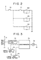
- the change-over valves 42, 45 and 46 are electromagnetic change-over valves, which are controlled for change-over by the control means shown in Figs. 2 and 3.
- the numeral 70 denotes a damper switch (a mode selection switch), which is turned ON and OFF to select the travelling mode and the operation mode, respectively.
- the boom position detecting means there may be used a detector which detects the angle of the boom 3, but in this embodiment there is used a stroke meter 71 which detects the length of the cylinder 50 shown in Fig. 7 and which is attached to the cylinder 50.
- Numeral 72 denotes an averaging filter
- numerals 73 and 74 denote an upper limit value setter and a lower limit value setter, respectively, whereby there are set upper and lower limit values of an appropriate travelling range with respect to the length of the cylinder 50 which values correspond to the boom heights H 2 and Hi.
- Numerals 75, 76 and 77 denote a discriminator, a relay and a contact of the relay 76, respectively.
- Numerals 421, 451 and 461 represent solenoids of the change-over valves 42, 45 and 46.
- the solenoids 421, 451 and 461 are deenergized and the change-over valves 42, 45 and 46 are held in the illustrated positions e, g and j, respectively, so that the pressure oil discharged from the auxiliary hydraulic pump 61 and regulated by an auxiliary relief valve 63 passes through the oil paths 62, 64 and the constriction 65 and enters the pilot oil paths 58, 59 to open the pilot check valves 43, 44. Since the accumulated pressure in the accumulator 53 is drained to a tank through the constriction 55 and the pilot check valve 44, the change-over valve 41 is held in the position c.
- a boom actuating hydraulic cylinder (not shown) is retracted in the operation mode to bring the boom 3 substantially into a most retracted state, and the boom 3 is brought down to the bottom dead center Ho or thereabouts by retracting the boom raising and lowering hydraulic cylinder 50. Further, the suspended goods are removed and the crane hook (not shown) is retained for moderate movement to the car body 2.
- the damper switch 70 when the damper switch 70 is turned ON (operation mode), the solenoids 421 and 451 are energized to change over the positions of the change-over valves 42 and 45 to f and h, respectively.
- the oil path 54 is brought into communication with the oil path 35, while the pilot oil paths 58, 59 and 66 are communicated with the drain oil path 57, so that the pilot check valves 43 and 44 are closed.
- the accumulated pressure in the accumulator 53 is equal to the tank pressure and is below the preset pressure level, and the change-over valve 41 is held in the position c.
- the cylinder 50 is in its most retracted state and the detected value by the stroke meter 71 is below the value set by the lower limit value setter 74, so an ON signal is outputted from the discriminator 75 and the relay 76 is energized to close the contact 77. Consequently, the solenoid 461 is energized and the change-over valve 46 is changed over to the position k. As a result, the discharged oil from the auxiliary hydraulic pump 61 passes through the check valve 68 and enters the accumulator 53. Thus, the oil pressure is accumulated gradually.
- the accumulated pressure in the accumulator 53 is conducted to the pilot oil path 56 through the constriction 55, and when it becomes the preset pressure level or higher, the change-over valve 41 is changed over to the position d by that pressure, so that the oil paths 34 and 35 are communicated with each other to form a closed loop. Further, since the change-over valve 42 is in the position f, the accumulator 53 is brought into communication with the said closed loop.
- the change-over valve 41 When the change-over valve 41 is changed over to the position d, though not simultaneously, the discharged oil from the auxiliary hydraulic pump 61 passes through the position f and enters the oil path 35, then further passes the position c or d in the change-over valve 41 and enters the first oil chamber 51 of the cylinder 50. After the change-over valve 41 has been changed over to the position d, the discharged oil from the auxiliary hydraulic pump 61 enters the accumulator 53 and the above closed loop, whereby the cylinder 50 is extended in the same manner as in the case of a ram cylinder to raise the boom gradually from the bottom dead center Ho.
- the relay 76 When the length of the cylinder 50 exceeds the upper limit value of the appropriate travelling range, the relay 76 is de-energized with a signal provided from the discriminator 75 to open the contact 77, whereby the solenoid 461 is de-energized and the change-over valve 46 is returned to the position j.
- the supply of the pressure oil from the auxiliary hydraulic pump 61 to the accumulator 53 and the cylinder 50 is stopped, the length of the cylinder 50 is set in the appropriate travelling length range, and the height of the boom 3 is set in the appropriate travelling height range of H 1 to H 2 .
- the mode selection switch 70 By changing over the mode selection switch 70 to the travelling mode, the accumulation of pressure to the accumulator 53 and the adjustment of the height of the boom 3 are performed automatically.
- the car 1 is driven for travel by means of a driving unit (not shown).
- a driving unit not shown.
- the car body 2 vibrates due to ruggedness of the road surface or sudden acceleration or deceleration
- the boom 3 rocks up and down, so that the cylinder 50 tends to extend or withdraw.
- the oil chambers 51, 52 of the cylinder 50 and the accumulator 53 are in communication with each other, the change in pressure and the displacement of the boom 3 and that of the car body 2 which are caused by the extension or withdrawal of the cylinder 50 are suppressed by a vibration damping action induced by the accumulated pressure in the accumulator 53 and a damping action induced by pressure loss in the oil paths for example, whereby comfortableness is improved.
- the length of the cylinder 50 is detected by the stroke meter 71 and the detected value is compared with the values which have been set by the setters 73 and 74. At this time, even if the cylinder 50 withdraws very small strokes due to vibrations, the detected stroke values are averaged by the averaging filter 72 and the average value obtained is fed to the discriminator 75 and compared with the above set values.
- the oil which entered the above closed loop does not enter the accumulator 53 but enters the first oil chamber 51 of the cylinder 50 to extend the cylinder.
- the length of the cylinder 50 is restored automatically to a length within the appropriate travelling length range and the height of the boom 3 also restored automatically to a height within the appropriate travelling range of H 1 to H 2 .
- the height of the boom 3 is adjusted automatically to the appropriate range, it is not necessary for the operator to check the height of the boom 3 at all times; that is, the operator can devote all his energies to steering. Even during travel for a long time, the above desplacement suppressing action can be exhibited properly.
- Fig. 4 illustrates an embodiment using an accumulator 81 for replenishment separately from the accumulator 53 for the suppression of vibration.
- the accumulator 81 there is accumulated pressure oil in an amount (required amount) corresponding to the amount of oil fed to the first oil chamber 51 which amount is required from extending the cylinder 50 from the lower limit to the upper limit value of the appropriate travelling range.
- Numerals 82 and 83 denote an unloading relief valve and a check valve, respectively.
- a position detector 84 for detecting the lower limit value of the appropriate travelling range is attached to the cylinder 50. As the detector 84 there is used a limit switch or a proximity switch. Other constructional points are substantially the same as in the embodiment illustrated in Fig. 1.
- the displacement suppressing action is exhibited by the accumulated pressure in the displacement suppressing accumulator 53 as in the embodiment illustrated in Fig. 1.
- the solenoid 461 is energized and the change-over valve 46 is changed over to the position k, so that the pressure oil in the replenishing accumulator 81 enters the closed loop including the cylinder 50 and flows into the first oil chamber 51 of the cylinder 50, whereby the cylinder 50 is extended automatically from the upper limit to the lower limit value of the appropriate travelling range, followed by exhibition of a predetermined displacement suppressing action.
- the pressure oil is replenished from the replenishing accumulator 81 only in an amount necessary for extending the cylinder from the lower limit to the upper limit value of the appropriate travelling range, so even in the amount of error or trouble of the detector 84 there is no fear of the length of the cylinder 50 exceeding the upper limit value of the appropriate range.
- the position detector 84 may detect only the aforesaid lower limit value;. As the detector 84, therefore, there may be used a limit switch or a proximity switch. In the detection, the position detector 84 sometimes repeats on-off operation near the lower limit value due to vibrations during travel of the crane. Therefore, ON time of the position detector 84 is detected by a time detector 85 and is inputted to a discriminator 86, as shown in Fig. 5. On the other hand, a natural frequency of the cylinder 50 during travel of the crane is known and if the lower limit value is detected at time intervals of 1/2 or more of the period of the vibration waveform, it can be judged that the cylinder length is at its lower limit value.
- 1/2 of time T calculated from the natural frequency of the cylinder 50 is set in a setter 87, and the relay 76 is operated, depending on whether the detected time by the time detector 85 is within the time (1/2T) thus set in the setter 87 or not, to energize the solenoid 461 for operation of the change-over valve 46.
- the change-over valve 46 is controlled on the basis of average values thereof, whereby it is possible to enhance controllability.
- the pressure oil from the auxiliary pressure oil source is supplied to the first oil chamber of the cylinder immediately to extend the cylinder, thereby restoring the boom to an appropriate height automatically and permitting a predetermined displacement suppressing action to be exhibited.
- the displacement suppressing action can always be exhibited properly without the necessity of the operator checking the height of the boom at all times.
- it is not necessary to adjust the height of the boom during travel of the crane that is, the operator can devote all his energies to steering, whereby the fatigue of the operator can be diminished to a great extent.
- the height of the boom can be restored to a height within the appropriate travelling height range.
- a change-over valve for replenishment capable of changing over the position of an auxiliary pressure oil source selectively to a communicating position for communication of the auxiliary pressure oil source with a first oil chamber of a boom raising and lowering hydraulic cylinder and a communication cutting-off position is shifted to the communicating position by a control means to supply a predetermined amount of pressure oil to the first oil chamber of the hydraulic cylinder.
Landscapes
- Engineering & Computer Science (AREA)
- Mechanical Engineering (AREA)
- Automation & Control Theory (AREA)
- Health & Medical Sciences (AREA)
- Public Health (AREA)
- Transportation (AREA)
- Jib Cranes (AREA)
- Control And Safety Of Cranes (AREA)
Applications Claiming Priority (1)
| Application Number | Priority Date | Filing Date | Title |
|---|---|---|---|
| JP1234055A JPH0639317B2 (ja) | 1989-09-09 | 1989-09-09 | 移動式クレーンの変位抑制機構 |
Publications (1)
| Publication Number | Publication Date |
|---|---|
| EP0482238A1 true EP0482238A1 (de) | 1992-04-29 |
Family
ID=16964872
Family Applications (1)
| Application Number | Title | Priority Date | Filing Date |
|---|---|---|---|
| EP90120393A Withdrawn EP0482238A1 (de) | 1989-09-09 | 1990-10-24 | Mechanismus zur Unterdrückung von Pendelbewegungen bei beweglichen Kränen |
Country Status (4)
| Country | Link |
|---|---|
| US (1) | US5007544A (de) |
| EP (1) | EP0482238A1 (de) |
| JP (1) | JPH0639317B2 (de) |
| KR (1) | KR930001766B1 (de) |
Families Citing this family (32)
| Publication number | Priority date | Publication date | Assignee | Title |
|---|---|---|---|---|
| SE508992C2 (sv) * | 1991-05-22 | 1998-11-23 | Einar Karlsson | Anordning för att dämpa svängningar i en hydraulisk lastkran |
| US5481874A (en) * | 1991-06-20 | 1996-01-09 | Caterpillar Inc. | Exhaust pressurizing circuit including flow amplification |
| EP0559792A1 (de) * | 1991-06-20 | 1993-09-15 | Caterpillar Inc. | Druckbeaufschlagung eines auslasses mit strömungsverstärkung |
| JP3609127B2 (ja) * | 1994-10-25 | 2005-01-12 | 日清紡績株式会社 | 油圧プレスのラム駆動用油圧回路 |
| US5706657A (en) * | 1996-04-12 | 1998-01-13 | Caterpillar Inc. | Ride control system with an auxiliary power source |
| US5937646A (en) * | 1997-07-10 | 1999-08-17 | Mi-Jack Products | Hydraulic charge boost system for a gantry crane |
| US6206913B1 (en) * | 1998-08-12 | 2001-03-27 | Vascular Innovations, Inc. | Method and system for attaching a graft to a blood vessel |
| US6267548B1 (en) * | 1998-12-10 | 2001-07-31 | Case Corporation | Automatic over center system |
| US7204086B2 (en) * | 2000-05-25 | 2007-04-17 | J.C Bamford Excavators Limited | Method of operating a hydraulic system for a loader machine |
| GB2365407B (en) | 2000-05-25 | 2003-10-08 | Bamford Excavators Ltd | Hydraulic system for wheeled loader |
| DE50107980D1 (de) * | 2001-02-17 | 2005-12-15 | Globemag L P | Hydraulischer Oszillator als Antrieb von Maschinen |
| US6634653B2 (en) * | 2001-07-17 | 2003-10-21 | Probir Chatterjea & Associates, Inc. | Ride control system for construction equipment |
| DE10250207A1 (de) * | 2002-10-28 | 2004-05-13 | Bosch Rexroth Ag | Dämpfungsvorrichtung |
| WO2006002205A2 (en) | 2004-06-21 | 2006-01-05 | Cole Jeffrey E | Truck assembly for a skateboard, wheeled platform, or vehicle |
| US7216876B2 (en) * | 2004-06-21 | 2007-05-15 | Cole Jeffrey E | Occupant-propelled fluid powered rotary device, truck, wheeled platform, or vehicle |
| US7040638B2 (en) * | 2004-06-21 | 2006-05-09 | Jeffrey Eaton Cole | Occupant-propelled fluid powered rotary device, truck, wheeled platform, or vehicle |
| US7232139B2 (en) * | 2004-06-21 | 2007-06-19 | Cole Jeffrey E | Truck assembly for a skateboard, wheeled platform, or vehicle |
| US7635136B2 (en) * | 2005-06-21 | 2009-12-22 | Jeffrey E. Cole | Truck assembly for a skateboard, wheeled platform, or vehicle |
| DE102006024731B3 (de) * | 2006-05-26 | 2007-08-16 | Cnh Baumaschinen Gmbh | Verfahren zur lagegerechten Ausrichtung einer an einem heb- und senkbaren Hubgerüst einer Arbeitsmaschine kippbar angeordeten Arbeitausrüstung sowie Arbeitsmaschine |
| US7487707B2 (en) * | 2006-09-27 | 2009-02-10 | Husco International, Inc. | Hydraulic valve assembly with a pressure compensated directional spool valve and a regeneration shunt valve |
| CN101746675B (zh) * | 2009-12-31 | 2012-05-02 | 三一汽车制造有限公司 | 起重机超起装置及其控制系统和控制方法 |
| CN102452610B (zh) * | 2010-10-20 | 2013-07-24 | 徐州重型机械有限公司 | 一种电源控制系统及移动式起重机 |
| CN102431911B (zh) * | 2011-09-29 | 2013-07-24 | 中联重科股份有限公司 | 吊臂伸缩的控制方法与控制装置以及工程机械 |
| CN102887455B (zh) * | 2012-09-26 | 2014-12-10 | 三一重工股份有限公司 | 超起装置预紧力控制方法、控制装置及控制系统 |
| US11015624B2 (en) | 2016-05-19 | 2021-05-25 | Steven H. Marquardt | Methods and devices for conserving energy in fluid power production |
| US10550863B1 (en) | 2016-05-19 | 2020-02-04 | Steven H. Marquardt | Direct link circuit |
| US10914322B1 (en) | 2016-05-19 | 2021-02-09 | Steven H. Marquardt | Energy saving accumulator circuit |
| US10247206B2 (en) * | 2016-12-22 | 2019-04-02 | Eagle Industry Co., Ltd. | Fluid circuit |
| CN117043472A (zh) | 2021-03-31 | 2023-11-10 | 伊格尔工业股份有限公司 | 流体回路 |
| CN117098921A (zh) | 2021-03-31 | 2023-11-21 | 伊格尔工业股份有限公司 | 流体回路 |
| EP4317706A4 (de) | 2021-03-31 | 2025-03-12 | Eagle Industry Co., Ltd. | Fluidkreislauf |
| US12435738B2 (en) | 2021-09-21 | 2025-10-07 | Eagle Industry Co., Ltd. | Fluid circuit |
Citations (9)
| Publication number | Priority date | Publication date | Assignee | Title |
|---|---|---|---|---|
| US3922854A (en) * | 1974-01-14 | 1975-12-02 | Poclain Sa | Hydraulic installation with energy storing means |
| US4039085A (en) * | 1976-06-10 | 1977-08-02 | Koehring Company | Crane with a pivoted boom and a float valve therefor |
| US4046270A (en) * | 1974-06-06 | 1977-09-06 | Marion Power Shovel Company, Inc. | Power shovel and crowd system therefor |
| US4085587A (en) * | 1975-11-03 | 1978-04-25 | Leslie H. Garlinghouse | Fail safe liquid power device |
| US4142368A (en) * | 1976-10-28 | 1979-03-06 | Welko Industriale S.P.A. | Hydraulic system for supplying hydraulic fluid to a hydraulically operated device alternately at pressures of different value |
| US4341149A (en) * | 1979-08-30 | 1982-07-27 | Caterpillar Tractor Co. | Selectively actuatable fluid control system for a work element |
| DE3301847A1 (de) * | 1983-01-20 | 1984-10-25 | Zettelmeyer-Baumaschinen GmbH, 5503 Konz | Auf raedern fahrbare baumaschine wie schaufellader, planierfahrzeug od.dgl. |
| FR2576850A1 (fr) * | 1985-02-07 | 1986-08-08 | Peugeot | Dispositif anti-roulis hydraulique |
| US4953723A (en) * | 1989-04-21 | 1990-09-04 | Kabushiki Kaisha Kobe Seiko Sho | Apparatus for suppressing quaky movements of mobile cranes |
Family Cites Families (3)
| Publication number | Priority date | Publication date | Assignee | Title |
|---|---|---|---|---|
| US3814265A (en) * | 1973-08-20 | 1974-06-04 | Harnischfeger Corp | Hydraulic crane control system having means for deactivating control valves when operating limit is exceeded |
| US4367673A (en) * | 1981-01-09 | 1983-01-11 | Dresser Industries, Inc. | System and method for controlling the elevation of a boom hoist device |
| US4674638A (en) * | 1983-03-17 | 1987-06-23 | Kobe Steel Ltd. | Control for deflection reduction means |
-
1989
- 1989-09-09 JP JP1234055A patent/JPH0639317B2/ja not_active Expired - Lifetime
-
1990
- 1990-04-06 US US07/505,401 patent/US5007544A/en not_active Expired - Fee Related
- 1990-04-30 KR KR1019900006086A patent/KR930001766B1/ko not_active Expired - Fee Related
- 1990-10-24 EP EP90120393A patent/EP0482238A1/de not_active Withdrawn
Patent Citations (9)
| Publication number | Priority date | Publication date | Assignee | Title |
|---|---|---|---|---|
| US3922854A (en) * | 1974-01-14 | 1975-12-02 | Poclain Sa | Hydraulic installation with energy storing means |
| US4046270A (en) * | 1974-06-06 | 1977-09-06 | Marion Power Shovel Company, Inc. | Power shovel and crowd system therefor |
| US4085587A (en) * | 1975-11-03 | 1978-04-25 | Leslie H. Garlinghouse | Fail safe liquid power device |
| US4039085A (en) * | 1976-06-10 | 1977-08-02 | Koehring Company | Crane with a pivoted boom and a float valve therefor |
| US4142368A (en) * | 1976-10-28 | 1979-03-06 | Welko Industriale S.P.A. | Hydraulic system for supplying hydraulic fluid to a hydraulically operated device alternately at pressures of different value |
| US4341149A (en) * | 1979-08-30 | 1982-07-27 | Caterpillar Tractor Co. | Selectively actuatable fluid control system for a work element |
| DE3301847A1 (de) * | 1983-01-20 | 1984-10-25 | Zettelmeyer-Baumaschinen GmbH, 5503 Konz | Auf raedern fahrbare baumaschine wie schaufellader, planierfahrzeug od.dgl. |
| FR2576850A1 (fr) * | 1985-02-07 | 1986-08-08 | Peugeot | Dispositif anti-roulis hydraulique |
| US4953723A (en) * | 1989-04-21 | 1990-09-04 | Kabushiki Kaisha Kobe Seiko Sho | Apparatus for suppressing quaky movements of mobile cranes |
Non-Patent Citations (1)
| Title |
|---|
| WORLD PATENT INDEX, accession no. 87-014074 [02], Derwent Publications Ltd, London, GB; & SU-A-1 263 755 (MOSC MINING INST.) * |
Also Published As
| Publication number | Publication date |
|---|---|
| KR910006084A (ko) | 1991-04-27 |
| JPH0639317B2 (ja) | 1994-05-25 |
| JPH0398994A (ja) | 1991-04-24 |
| KR930001766B1 (ko) | 1993-03-13 |
| US5007544A (en) | 1991-04-16 |
Similar Documents
| Publication | Publication Date | Title |
|---|---|---|
| US5007544A (en) | Mechanism for suppressing displacement of travelling crane | |
| US4995517A (en) | Mechanism for suppressing vibrations of travelling crane | |
| US6116618A (en) | Vehicular slope determination apparatus and vehicle height adjust control apparatus and vehicle height adjust control apparatus and method using the same | |
| KR930003321B1 (ko) | 가동 크레인의 흔들림 운동 억제장치 | |
| EP1188608B1 (de) | Aktives Aufhängungssystem mit Anpassung eines Entlastungselementes | |
| US6282470B1 (en) | Vehicle height adjust control apparatus and method | |
| KR100257087B1 (ko) | 산업차량용 유압제어장치 | |
| DE102013110526B4 (de) | Fahrzeughöheneinstellvorrichtung eines Motorrads | |
| JP6012356B2 (ja) | 自動二輪車の車高調整装置 | |
| EP0395108B1 (de) | Flüssigkeitsversorgungskreislauf für aktive Aufhängung mit von der Querbeschleunigung abhängiger variabler Durchflussrate der Flüssigkeitsquelle | |
| EP0249227A2 (de) | Aktiv geregeltes Fahrzeugaufhängungssystem mit unabhängigen hydraulischen Systemen und unabhängigen Dämpfungscharakteristiken zur Verbesserung des Antwortverhaltens in aktiven Fahrzeugaufhängungsregelungen | |
| EP0796749A2 (de) | Nutzfahrzeug | |
| EP0394706B1 (de) | Druckspeisendes Netz für ein aktives Aufhängungssystem und dessen Steuerung | |
| JP7041320B2 (ja) | ダンプトラックの荷台昇降装置 | |
| US20120155999A1 (en) | Travel vibration suppressing device of work vehicle | |
| US10895063B2 (en) | Energy regeneration device and work machine provided with energy regeneration device | |
| DE102013102585B4 (de) | Motorrad | |
| JPH0971117A (ja) | 建設機械のサスペンション装置およびその制御方法 | |
| US6298292B1 (en) | Vehicle height adjust control apparatus and method | |
| JPH05139267A (ja) | アウトリガ付き車輌の水平矯正方法 | |
| CN112746649A (zh) | 可调节的行驶控制系统 | |
| JPH0639315B2 (ja) | 移動式クレーンの変位抑制機構 | |
| EP0414984A1 (de) | Aktivaufhängungssystem mit verbesserten Ansprecheigenschaften des Hydraulikkreises | |
| JP2010149815A (ja) | 作業車のサスペンション構造 | |
| JP4731205B2 (ja) | 油圧シリンダの作動制御装置 |
Legal Events
| Date | Code | Title | Description |
|---|---|---|---|
| PUAI | Public reference made under article 153(3) epc to a published international application that has entered the european phase |
Free format text: ORIGINAL CODE: 0009012 |
|
| 17P | Request for examination filed |
Effective date: 19901024 |
|
| AK | Designated contracting states |
Kind code of ref document: A1 Designated state(s): DE ES FR GB IT NL |
|
| 17Q | First examination report despatched |
Effective date: 19930908 |
|
| STAA | Information on the status of an ep patent application or granted ep patent |
Free format text: STATUS: THE APPLICATION IS DEEMED TO BE WITHDRAWN |
|
| 18D | Application deemed to be withdrawn |
Effective date: 19940119 |