EP0481450B1 - Schalldämpferanlage für Verbrennungsmotoren - Google Patents
Schalldämpferanlage für Verbrennungsmotoren Download PDFInfo
- Publication number
- EP0481450B1 EP0481450B1 EP91117647A EP91117647A EP0481450B1 EP 0481450 B1 EP0481450 B1 EP 0481450B1 EP 91117647 A EP91117647 A EP 91117647A EP 91117647 A EP91117647 A EP 91117647A EP 0481450 B1 EP0481450 B1 EP 0481450B1
- Authority
- EP
- European Patent Office
- Prior art keywords
- resonator
- installation according
- silencer
- loudspeaker
- silencer installation
- Prior art date
- Legal status (The legal status is an assumption and is not a legal conclusion. Google has not performed a legal analysis and makes no representation as to the accuracy of the status listed.)
- Expired - Lifetime
Links
Images
Classifications
-
- F—MECHANICAL ENGINEERING; LIGHTING; HEATING; WEAPONS; BLASTING
- F01—MACHINES OR ENGINES IN GENERAL; ENGINE PLANTS IN GENERAL; STEAM ENGINES
- F01N—GAS-FLOW SILENCERS OR EXHAUST APPARATUS FOR MACHINES OR ENGINES IN GENERAL; GAS-FLOW SILENCERS OR EXHAUST APPARATUS FOR INTERNAL-COMBUSTION ENGINES
- F01N1/00—Silencing apparatus characterised by method of silencing
- F01N1/02—Silencing apparatus characterised by method of silencing by using resonance
- F01N1/023—Helmholtz resonators
-
- F—MECHANICAL ENGINEERING; LIGHTING; HEATING; WEAPONS; BLASTING
- F01—MACHINES OR ENGINES IN GENERAL; ENGINE PLANTS IN GENERAL; STEAM ENGINES
- F01N—GAS-FLOW SILENCERS OR EXHAUST APPARATUS FOR MACHINES OR ENGINES IN GENERAL; GAS-FLOW SILENCERS OR EXHAUST APPARATUS FOR INTERNAL-COMBUSTION ENGINES
- F01N1/00—Silencing apparatus characterised by method of silencing
- F01N1/06—Silencing apparatus characterised by method of silencing by using interference effect
- F01N1/065—Silencing apparatus characterised by method of silencing by using interference effect by using an active noise source, e.g. speakers
-
- F—MECHANICAL ENGINEERING; LIGHTING; HEATING; WEAPONS; BLASTING
- F01—MACHINES OR ENGINES IN GENERAL; ENGINE PLANTS IN GENERAL; STEAM ENGINES
- F01N—GAS-FLOW SILENCERS OR EXHAUST APPARATUS FOR MACHINES OR ENGINES IN GENERAL; GAS-FLOW SILENCERS OR EXHAUST APPARATUS FOR INTERNAL-COMBUSTION ENGINES
- F01N1/00—Silencing apparatus characterised by method of silencing
- F01N1/16—Silencing apparatus characterised by method of silencing by using movable parts
- F01N1/22—Silencing apparatus characterised by method of silencing by using movable parts the parts being resilient walls
-
- F—MECHANICAL ENGINEERING; LIGHTING; HEATING; WEAPONS; BLASTING
- F16—ENGINEERING ELEMENTS AND UNITS; GENERAL MEASURES FOR PRODUCING AND MAINTAINING EFFECTIVE FUNCTIONING OF MACHINES OR INSTALLATIONS; THERMAL INSULATION IN GENERAL
- F16L—PIPES; JOINTS OR FITTINGS FOR PIPES; SUPPORTS FOR PIPES, CABLES OR PROTECTIVE TUBING; MEANS FOR THERMAL INSULATION IN GENERAL
- F16L55/00—Devices or appurtenances for use in, or in connection with, pipes or pipe systems
- F16L55/02—Energy absorbers; Noise absorbers
- F16L55/033—Noise absorbers
- F16L55/0333—Noise absorbers by means of an active system
-
- G—PHYSICS
- G10—MUSICAL INSTRUMENTS; ACOUSTICS
- G10K—SOUND-PRODUCING DEVICES; METHODS OR DEVICES FOR PROTECTING AGAINST, OR FOR DAMPING, NOISE OR OTHER ACOUSTIC WAVES IN GENERAL; ACOUSTICS NOT OTHERWISE PROVIDED FOR
- G10K11/00—Methods or devices for transmitting, conducting or directing sound in general; Methods or devices for protecting against, or for damping, noise or other acoustic waves in general
- G10K11/16—Methods or devices for protecting against, or for damping, noise or other acoustic waves in general
- G10K11/175—Methods or devices for protecting against, or for damping, noise or other acoustic waves in general using interference effects; Masking sound
- G10K11/178—Methods or devices for protecting against, or for damping, noise or other acoustic waves in general using interference effects; Masking sound by electro-acoustically regenerating the original acoustic waves in anti-phase
- G10K11/1785—Methods, e.g. algorithms; Devices
- G10K11/17861—Methods, e.g. algorithms; Devices using additional means for damping sound, e.g. using sound absorbing panels
-
- G—PHYSICS
- G10—MUSICAL INSTRUMENTS; ACOUSTICS
- G10K—SOUND-PRODUCING DEVICES; METHODS OR DEVICES FOR PROTECTING AGAINST, OR FOR DAMPING, NOISE OR OTHER ACOUSTIC WAVES IN GENERAL; ACOUSTICS NOT OTHERWISE PROVIDED FOR
- G10K11/00—Methods or devices for transmitting, conducting or directing sound in general; Methods or devices for protecting against, or for damping, noise or other acoustic waves in general
- G10K11/16—Methods or devices for protecting against, or for damping, noise or other acoustic waves in general
- G10K11/175—Methods or devices for protecting against, or for damping, noise or other acoustic waves in general using interference effects; Masking sound
- G10K11/178—Methods or devices for protecting against, or for damping, noise or other acoustic waves in general using interference effects; Masking sound by electro-acoustically regenerating the original acoustic waves in anti-phase
- G10K11/1787—General system configurations
- G10K11/17873—General system configurations using a reference signal without an error signal, e.g. pure feedforward
-
- F—MECHANICAL ENGINEERING; LIGHTING; HEATING; WEAPONS; BLASTING
- F01—MACHINES OR ENGINES IN GENERAL; ENGINE PLANTS IN GENERAL; STEAM ENGINES
- F01N—GAS-FLOW SILENCERS OR EXHAUST APPARATUS FOR MACHINES OR ENGINES IN GENERAL; GAS-FLOW SILENCERS OR EXHAUST APPARATUS FOR INTERNAL-COMBUSTION ENGINES
- F01N2210/00—Combination of methods of silencing
- F01N2210/02—Resonance and interference
-
- G—PHYSICS
- G10—MUSICAL INSTRUMENTS; ACOUSTICS
- G10K—SOUND-PRODUCING DEVICES; METHODS OR DEVICES FOR PROTECTING AGAINST, OR FOR DAMPING, NOISE OR OTHER ACOUSTIC WAVES IN GENERAL; ACOUSTICS NOT OTHERWISE PROVIDED FOR
- G10K2210/00—Details of active noise control [ANC] covered by G10K11/178 but not provided for in any of its subgroups
- G10K2210/10—Applications
- G10K2210/112—Ducts
-
- G—PHYSICS
- G10—MUSICAL INSTRUMENTS; ACOUSTICS
- G10K—SOUND-PRODUCING DEVICES; METHODS OR DEVICES FOR PROTECTING AGAINST, OR FOR DAMPING, NOISE OR OTHER ACOUSTIC WAVES IN GENERAL; ACOUSTICS NOT OTHERWISE PROVIDED FOR
- G10K2210/00—Details of active noise control [ANC] covered by G10K11/178 but not provided for in any of its subgroups
- G10K2210/10—Applications
- G10K2210/128—Vehicles
- G10K2210/1282—Automobiles
- G10K2210/12822—Exhaust pipes or mufflers
-
- G—PHYSICS
- G10—MUSICAL INSTRUMENTS; ACOUSTICS
- G10K—SOUND-PRODUCING DEVICES; METHODS OR DEVICES FOR PROTECTING AGAINST, OR FOR DAMPING, NOISE OR OTHER ACOUSTIC WAVES IN GENERAL; ACOUSTICS NOT OTHERWISE PROVIDED FOR
- G10K2210/00—Details of active noise control [ANC] covered by G10K11/178 but not provided for in any of its subgroups
- G10K2210/30—Means
- G10K2210/321—Physical
- G10K2210/3224—Passive absorbers
-
- G—PHYSICS
- G10—MUSICAL INSTRUMENTS; ACOUSTICS
- G10K—SOUND-PRODUCING DEVICES; METHODS OR DEVICES FOR PROTECTING AGAINST, OR FOR DAMPING, NOISE OR OTHER ACOUSTIC WAVES IN GENERAL; ACOUSTICS NOT OTHERWISE PROVIDED FOR
- G10K2210/00—Details of active noise control [ANC] covered by G10K11/178 but not provided for in any of its subgroups
- G10K2210/30—Means
- G10K2210/321—Physical
- G10K2210/3227—Resonators
- G10K2210/32272—Helmholtz resonators
Definitions
- the invention relates to silencer systems for internal combustion engines according to the preamble of claim 1.
- Conventional exhaust systems of motor vehicles with internal combustion engines usually have several silencers - front, main and / or rear silencer - which are connected to each other and to the engine via one or more exhaust pipes.
- the task of the silencers is to reduce the acoustic energy contained in the exhaust gases of the internal combustion engine to a level that is tolerable for the environment, without reducing the power of the engine more than is absolutely necessary.
- the reflection principle includes precisely dimensioned resonators, which operate according to the principles of the Helmholtz resonator or the lambda quarter line.
- the circuit arrangement used for this purpose consists of a microphone which records the sound events in the Helmholtz resonator, a measuring amplifier, an adjustable phase shifter and a power amplifier which feeds a loudspeaker acoustically coupled to the Helmholtz resonator.
- the acoustic level of the noise generated by the flow could be increased by up to 40 in the laboratory dB can be reduced.
- test facility used consists of an exhaust pipe to which a Helmholtz resonator is coupled via a coupling pipe.
- the bottom of the Helmholtz resonator is formed by a piston that is mechanically adjustable by means of a stepper motor.
- Microphones in the exhaust pipe and in the Helmholtz resonator record the sound events, which are processed in a personal computer and control the stepper motor in such a way that the resonance frequency of the Helmholtz resonator is controlled as desired via the displacement of the piston.
- the Helmholtz resonator itself is only acoustically excited by the exhaust gases.
- the present invention has for its object to provide a silencer system of the type mentioned, with which it is possible to further reduce the muzzle noise in any case in the desired frequency ranges with little effort.
- the present invention takes advantage of the fact that the sound attenuation of the conventional passive silencer systems is already quite good and only needs to be further improved in the low-frequency range, preferably between 40 and 200 Hz, and that both the source of the exhaust noise and the acoustic properties the silencer system to be improved are known or can be determined with simple means.
- the acoustic properties of the silencer system itself are construction-related and can be determined with sufficient accuracy by measurement.
- the source of the exhaust noise is the internal combustion engine, the acoustic properties of which can also be determined by measurement.
- the temperature of the exhaust gases has a significant influence on the acoustic properties of the silencer system, because the speed of sound is between approx. 330 m / sec. at ambient temperature and approx. 600 m / sec. varies at the higher exhaust gas temperatures.
- the temperature of the exhaust gases correlates with the load condition of the engine.
- the present invention preferably uses a controller instead of a controller like the prior art. This considerably reduces the demands on the electronics, the electronics work faster and highly dynamic processes can be mastered better. However, mixed systems with rough pilot control and fine regulation are also conceivable.
- the required electrical power is low, which is further supported by the fact that the controlled resonance elements only reduce the noise by between 10 and 20 dB must, since the major part of the noise reduction, especially in the range of high frequencies, is provided by the passive silencers built in conventional technology.
- a temperature sensor is preferably inserted into the exhaust line for temperature measurement.
- the exhaust gas temperature can also indirectly via the load state of the engine and this z. B. can be determined by the position of the throttle valve or the negative pressure in the intake line.
- a throttle position sensor or a vacuum sensor is preferably provided. These sensors are not subject to thermal loads and are already present in fuel injection systems.
- a pressure sensor in particular a microphone, can be inserted into the exhaust line, as is known per se.
- the Helmholtz resonator is coupled to the exhaust pipe as a pressure or suction resonator.
- the rear of the loudspeaker is decoupled from the surroundings with the aid of an acoustically rigid housing, the inside of which may be filled with sound-absorbing material.
- an acoustically rigid housing the inside of which may be filled with sound-absorbing material.
- the loudspeaker itself is positioned inside the Helmholtz resonator, in particular as close as possible to the wall of the resonator in which the coupling tube opens.
- the Helmholtz resonator itself takes on the task of preventing the anti-noise from being emitted to the environment, so that separate shielding measures can be dispensed with.
- the Helmholtz resonator can be coupled to the exhaust pipe at any point, for example directly behind the engine, between two passive silencers or behind the last passive silencer.
- the sound-absorbing effect is greatest when the Helmholtz resonator is coupled directly behind the engine; however, this variant requires extremely high anti-switching performance, since the sound level of the exhaust gases reaches up to 170 dB here.
- the lowest anti-switching performance is required if the Helmholtz resonator is coupled to the end of the exhaust pipe, where the exhaust pipe opens into the open.
- the known physical effect can be exploited that the sound level when exiting the muzzle tube is reduced by 20 dB due to the jump in impedance.
- the Helmholtz resonator and / or coupling tube are made at least partially made of plastic. This applies in particular to the resonator parts which are further away from the exhaust gas-carrying line. The exhaust gas does not flow through them and is therefore practically not heated.
- the resonator can also be accommodated in the motor vehicle, separated from the exhaust pipe and / or silencers. Cavities in the vehicle that are not used otherwise would be suitable, and thanks to the plastic material, any geometric shapes can be produced for optimal use of space.
- the spatial-constructive coupling of the actuator to the resonator must take account of the acoustic and spatial conditions.
- a possible coupling is to use a conical tube that widens outwards, in particular an exponential tube.
- sensors - temperature and / or pressure sensors - are used in the exhaust pipe, it is advisable to position them upstream of the resonator.
- the acoustic data of the silencer system and / or of the engine are stored in the control box of the electronics.
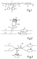
- Fig. 1 shows schematically a silencer system, consisting of an exhaust pipe 1, which connects the front silencer 2, main silencer 3 and rear silencer 4 to each other and to an internal combustion engine, not shown in the drawing.
- a sensor 5 for example a pressure sensor, a microphone or a temperature sensor, is coupled to the line 1 behind the front silencer 2.
- the signals picked up by sensor 5 are sent to electronics 8, compared with the data possibly stored in the so-called control box, processed and fed to a loudspeaker 7.
- This is coupled to a Helmholtz resonator 6, which is in turn coupled to the exhaust pipe 1 by means of a coupling pipe 9.
- the resonance frequency, resonance magnification and resonance range of the resonator 6 in such a way that the switching power at the mouth of the coupling tube 9 into the exhaust pipe 1 is reduced by interference in the frequency range detected by the resonator 6.
- the high frequencies are still attenuated by the silencer pots 2, 3, 4, which are manufactured using conventional technology.
- FIG. 2 shows the use of a Helmholtz resonator 6.2 as a resonance element, here in a two-pipe silencer system.
- the electrodynamic loudspeaker 7.1 is directly coupled to the Helmholtz resonator 6.2. In this way, the resonance frequency, increase and range of the Helmholtz resonator 6.2 can be actively influenced within the design limits.
- the loudspeaker 7.1 is seated in an acoustically rigid housing 7.2, the inside of which is optionally lined with sound-absorbing material 7.3. In this way it is prevented that the anti-noise generated by the loudspeaker 7.1 reaches the surroundings and that the housing 7.2 also generates additional disturbing resonances.
- the Helmholtz resonator 6.2 is coupled to the two exhaust pipes 1, 1 'via a coupling pipe 9, 9'.
- Suitable flow blocking means must be built into this, which, however, must not hinder the excitation of acoustic vibrations by the loudspeaker 7.1 and their transmission via the coupling tubes 9, 9 '.
- Fig. 3 shows a further embodiment of a two-pipe muffler system, as used for example for six-cylinder engines.
- a special feature of this system can be seen in the fact that the two exhaust pipes 1, 1 'have a common mixing section 1' 'in which, for example, a lambda probe 10 required for controlling the engine is seated.
- the Helmholtz resonator 6.1 with loudspeaker 7.1 is now also coupled to this common mixing section 1 ′′ via the coupling tube 9.
- Fig. 3 shows as a further special feature that it is possible to position the loudspeaker 7.1 inside the Helmholtz resonator 6.1, preferably in such a way that the loudspeaker membrane is positioned as close as possible to the wall in which the coupling tube 9 opens. If the membrane of the loudspeaker 7.1 is conical as usual, it is advisable to also design the corresponding resonator wall to be conical. With such a deposition of the loudspeaker 7.1, there is no need to use a separate acoustic shielding housing 7.2.
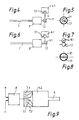
- FIG. 4 schematically shows a first variant for coupling the Helmholtz resonator 6.1 to the mouth end 1.1 of the exhaust gas line 1.
- the mouth end 1.1 there is an outlet chamber 11 which is open on the outlet side and into which the coupling tube 9 opens.
- FIG 5 shows a top view of how the outlet chamber 11 surrounds the outlet 1.1 of the exhaust pipe 1 symmetrically on all sides. This arrangement forms an acoustic quadrupole.
- FIG. 6 schematically shows a further variant of the coupling.
- the end 9.1 of the coupling pipe 9 ends here directly next to the mouth end 1.1 of the exhaust pipe 1.
- Fig. 7 shows a top view of a first arrangement of the two pipe mouths 1.1, 9.1. This arrangement forms an acoustic dipole.
- Fig. 8 shows a top view of a second arrangement of the two pipe mouths 1.1, 9.1. Both are combined to form a double D tube.
- Fig. 9 shows schematically a control circuit for use in the silencer system according to the invention.
- the electronics 8 are supplied with the current values for engine speed n and exhaust gas temperature T.
- the acoustic data of the muffler system and / or the engine are stored in a suitable form in the control box of the electronics 8, for example as a digital table.
- a tachometer is available in every motor vehicle.
- the exhaust gas temperature can either be measured directly via a temperature sensor or determined indirectly via the position of the throttle valve, the negative pressure in the intake manifold or the exhaust back pressure. The latter variants have the advantage that the sensor is not exposed to hot exhaust gases.
- a plurality of resonators 6 can also be coupled to the exhaust pipe 1 in order to influence a wide frequency range.
- the power required to excite the loudspeaker 7 is relatively low thanks to the principle of resonance.
- the resonators 6 themselves can be set apart from the muffler system manufactured in conventional technology at suitable locations — in unused locations Cavities - housed in the motor vehicle and also made of light plastic materials in almost any shape.
Landscapes
- Engineering & Computer Science (AREA)
- General Engineering & Computer Science (AREA)
- Mechanical Engineering (AREA)
- Physics & Mathematics (AREA)
- Acoustics & Sound (AREA)
- Multimedia (AREA)
- Chemical & Material Sciences (AREA)
- Combustion & Propulsion (AREA)
- Exhaust Silencers (AREA)
- Soundproofing, Sound Blocking, And Sound Damping (AREA)
Description
- Die Erfindung betrifft Schalldämpferanlagen für Verbrennungsmotoren gemäß dem Oberbegriff des Anspruchs 1.
- Herkömmliche Abgasanlagen von Kraftfahrzeugen mit Verbrennungsmotoren besitzen meist mehrere Schalldämpfer - Vor-, Haupt- und/oder Nachschalldämpfer - , die untereinander und mit dem Motor über eine oder mehrere Abgasleitungen verbunden sind. Aufgabe der Schalldämpfer ist es, die in den Abgasen des Verbrennungsmotors enthaltene akustische Energie auf ein für die Umgebung erträgliches Maß zu reduzieren, ohne dabei die Leistung des Motors mehr als unbedingt nötig zu reduzieren.
- Derzeit werden in der Praxis ausschließlich passive Schalldämpfer eingesetzt. In diesen erfolgt die Schalldämpfung nach den Prinzipien der Absorption und der Reflexion. Zum Reflexionsprinzip gehören exakt dimensionierte Resonatoren, die nach den Prinzipien des Helmholtz-Resonators bzw. der Lambda-Viertel-Leitung wirken.
- Der Bau herkömmlicher Schalldämpferanlagen stellt einen Kompromiß dar zwischen der Forderung des Gesetzgebers nach immer besserer Schalldämpfung einerseits und der Automobilindustrie nach immer kleineren Abmessungen und Gewichten andererseits. Die Gesetze der Physik verlangen, daß die Volumina der Schalldämpfer auf die zu beeinflussenden Frequenzen abgestimmt sind. Je tiefer die Frequenz, desto größer das Volumen. Verschärft wird dieser Effekt noch dadurch, daß die Schallgeschwindigkeit in den heißen Abgasen bis auf ca. 600 m/sec. ansteigt.
- Bereits in den 30er Jahren des 20. Jahrhunderts war entdeckt worden, daß es grundsätzlich möglich ist, die Schallenergie in den Kraftfahrzeugabgasen mit Hilfe der Interferenz, d. h. durch Überlagerung der unerwünschten Schallwellen mit exakt spiegelverkehrten Schwingungsverläufen, zu reduzieren (US 2 043 416). Auf diesem Prinzip basierende Versuchsanlagen verwenden ein Mikrofon, welches den Schall der Abgase mißt. In einem Mikroprozessor wird das Geräusch analysiert, verstärkt und um 180 Grad phasenverschoben. Mit diesem künstlichen Geräusch werden zwei Lautsprecher angeregt, die in einer das Abgasrohr umschließenden Kammer sitzen. Am Rohrende treffen die Schallwellen mit exakt 180 Grad Phasenverschiebung aufeinander und löschen sich weitgehend aus (WO 89/07701 A1).
- Ein Vorteil dieser aktiven Schalldämpfer ist eine deutliche Verringerung von Gewicht und Volumen sowie eine Verringerung der Motorleistungsverluste aufgrund der Reduzierung des Abgasgegendrucks. Problematisch sind jedoch die hohen akustischen Leistungen, die von den Lautsprechern erzeugt werden müssen. Immerhin liegt die Intensität der ungedämpfen Abgasgeräusche bei 160 - 170 dB. Kein Lautsprecher kann diese Schallpegel erzeugen. Auch sind die Lausprecher durch die Abgaspulsationen und -temperaturen stark belastet.
- In der Zeitschrift "ACUSTICA" 1989, S. 175 ist beschrieben, daß es mit Hilfe einer elektromechanischen Rückkopplungskompensation möglich ist, einen durch Gasströmung angeregten Helmholtz-Resonator so zu beeinflussen, daß darin selbsterzeugte akustische Schwingungen nicht oder nur sehr schwach entstehen können. Die hierzu verwendete Schaltungsanordnung besteht aus einem Mikrofon, welches die Schallereignisse im Helmholtz-Resonator aufnimmt, einem Meßverstärker, einem einstellbaren Phasenschieber und einem Leistungsverstärker, der einen akustisch an den Helmholtz-Resonator angekoppelten Lautsprecher speist. Der akustische Pegel des durch die Strömung generierten Geräusches konnte im Labor um bis zu 40 dB abgesenkt werden.
- In den Konferenzpapieren der "Internoise 90" findet sich ab Seite 1305 ein Aufsatz "SEMI-ACTIVE NOISE CONTROL BY A RESONATOR WITH VARIABLE PARAMETERS", welcher auf Arbeiten am Department of Precision Mechanics, Kyoto University, basiert. Die verwendete Versuchsanlage besteht aus einem Abgasrohr, an das über ein Koppelrohr ein Helmholtz-Resonator angekoppelt ist. Den Boden des Helmholtz-Resonators bildet ein Kolben, der mittels Schrittmotor mechanisch verstellbar ist. Mikrofone in der Abgasleitung und im Helmholtz-Resonator nehmen die Schallereignisse auf, die in einem Personal Computer verarbeitet werden und den Schrittmotor so steuern, daß über die Verschiebung des Kolbens die Resonanzfrequenz des Helmholtz-Resonators wunschgemäß eingesteuert wird. Der Helmholtz-Resonator selbst wird lediglich durch die Abgase akustisch angeregt.
- Auch mit diesen Experimentalsystemen konnten bei statischen Verhältnissen gute Kompensationswerte erzielt werden. Für hochdynamische Anwendungsfälle, wie sie bei Schalldämpferanlagen für Verbrennungsmotoren in Kraftfahrzeugen im praktischen Betrieb gegeben sind, ist jedoch auch dieses System noch völlig ungeeignet.
- Der vorliegenden Erfindung liegt die Aufgabe zugrunde, eine Schalldämpferanlage der eingangs genannten Art anzugeben, mit der es möglich ist, das Mündungsgeräusch jedenfalls in gewünschten Frequenzbereichen mit geringem Aufwand weiter zu reduzieren.
- Diese Aufgabe wird gelöst durch eine Schalldämpferanlage der gattungsgemäßen Art mit den Merkmalen gemäß Kennzeichen des Anspruchs 1.
- Die vorliegende Erfindung macht sich die Tatsache zunutze, daß die Schalldämpfung der herkömmlichen, passiven Schalldämpferanlagen schon recht gut ist und nur im tieffrequenten Bereich, vorzugsweise zwischen 40 und 200 Hz, weiter verbessert werden muß und daß sowohl die Quelle der Abgasgeräusche als auch die akustischen Eigenschaften der zu verbessernden Schalldämpferanlage bekannt bzw. mit einfachen Mitteln bestimmbar sind. Die akustischen Eigenschaften der Schalldämpferanlage selbst sind konstruktionsbedingt und können durch Messung ausreichend genau bestimmt werden. Die Quelle der Abgasgeräusche ist der Verbrennungsmotor, dessen akustische Eigenschaften ebenfalls durch Messung bestimmt werden können. Schließlich hat noch die Temperatur der Abgase einen wesentlichen Einfluß auf die akustischen Eigenschaften der Schalldämpferanlage, weil die Schallgeschwindigkeit zwischen ca. 330 m/sec. bei Umgebungstemperatur und ca. 600 m/sec. bei den höheren Abgastemperaturen variiert. Die Temperatur der Abgase korrelliert mit dem Lastzustand des Motors. Diese Zusammenhänge sind in der Fachwelt bekannt.
- Da die wesentlichen Einflußfaktoren als bekannt vorausgesetzt werden können, verwendet die vorliegende Erfindung vorzugsweise eine Steuerung statt einer Regelung wie der Stand der Technik. Dadurch werden die Anforderungen an die Elektronik erheblich reduziert, die Elektronik arbeitet dadurch schneller und hochdynamische Vorgänge lassen sich besser beherrschen. Es sind aber auch gemischte Anlagen mit einer groben Vorsteuerung und einer feinen Ausregelung denkbar.
- Dank der Ausnützung des Resonanzeffektes sind die benötigten elektrischen Leistungen gering, was noch wesentlich dadurch unterstützt wird, daß die gesteuerten Resonanzelemente nur eine Geräuschreduzierung zwischen 10 und 20 dB bewirken müssen, da der wesentliche Teil der Geräuschdämpfung, insbesondere im Bereich der hohen Frequenzen, von den in herkömmlicher Technik gebauten passiven Schalldämpfern geleistet wird.
- Vorzugsweise ist zur Temperaturmessung ein Temperatursensor in die Abgasleitung eingesetzt. Die Abgastemperatur kann jedoch auch indirekt über den Lastzustand des Motors und dieser z. B. durch die Stellung der Drosselklappe oder den Unterdruck in der Ansaugleitung bestimmt werden. In diesem Fall ist vorzugsweise ein Drosselklappen-Positionssensor oder ein Unterdrucksensor vorgesehen. Diese Sensoren sind keinen thermischen Belastungen unterworfen und sind bei Kraftstoffeinspritzsystemen bereits vorhanden.
- Für den Fall, daß der Steuerkreis zu einem Regelkreis erweitert werden soll, kann wie an sich bekannt ein Drucksensor, insbesondere ein Mikrofon, in die Abgasleitung eingesetzt werden.
- Gemäß einer bevorzugten Ausgestaltung der Erfindung ist der Helmholtz-Resonator als Druck- oder Saugresonator an die Abgasleitung angekoppelt. Diese beiden Varianten haben den Vorteil, daß die Abgasströmung an der Ankoppelstelle wenig Wirbel erzeugt, wodurch entsprechend wenig Zusatzgeräusche entstehen.
- Gemäß einer vorteilhaften Ausgestaltung der Erfindung ist der Lautsprecher rückseitig mit Hilfe eines akustisch steifen Gehäuses, dessen Innenseite gegebenenfalls mit schallabsorbierendem Material gefüllt ist, von der Umgebung entkoppelt. Dadurch wird mit einfachen Mitteln eine unerwünschte Abstrahlung des vom Lautsprecher erzeugten Anti-Schalls in die Umgebung verhindert, wobei das schallabsorbierende Material die Entstehung unerwünschter zusätzlicher Resonanzen verhindert.
- Besonders vorteilhaft ist es jedoch, wenn der Lautsprecher selbst im Inneren des Helmholtz-Resonators positioniert wird, und zwar insbesondere möglichst nahe an der Wand des Resonators, in der das Koppelrohr mündet. Bei dieser Variante übernimmt der Helmholtz-Resonator selbst die Aufgabe, die unerwünschte Abstrahlung des Anti-Schalls an die Umgebung zu verhindern, so daß auf gesonderte Abschirmmaßnahmen verzichtet werden kann.
- Grundsätzlich kann der Helmholtz-Resonator an jeder beliebigen Stelle an die Abgasleitung angekoppelt werden, beispielsweise direkt hinter dem Motor, zwischen zwei passiven Schalldämpfern oder auch hinter dem letzten passiven Schalldämpfer. Der schalldämpfende Effekt ist am größten, wenn der Helmholtz-Resonator direkt hinter dem Motor angekoppelt wird; diese Variante erfordert jedoch extrem hohe Anti-Schalleistungen, da der Schallpegel der Abgase hier bis 170 dB erreicht.
- Die geringste Anti-Schalleistung ist erforderlich, wenn der Helmholtz-Resonator am Ende der Abgasleitung angekoppelt wird, dort wo die Abgasleitung ins Freie mündet. Hier kann der bekannte physikalische Effekt ausgenützt werden, daß der Schallpegel beim Austritt aus dem Mündungsrohr durch den Impedanzsprung um 20 dB abgesenkt wird.
- Für die Ankopplung des Helmholtz-Resonators an die Mündung der Abgasleitung gibt es zwei Möglichkeiten; entweder läßt man das Ende des Koppelrohrs unmittelbar neben dem Ende der Abgasleitung enden oder man sieht eine ausgangsseitig offene Mündungskammer vor, die das Ende der Abgasleitung umfaßt und in die das Koppelrohr mündet.
- Gemäß einer bevorzugten Ausgestaltung der Erfindung bestehen Helmholtz-Resonator und/oder Koppelrohr wenigstens teilweise aus Kunststoff. Dies gilt insbesondere für die von der abgasführenden Leitung weiter entfernten Resonatorteile. Diese sind nicht vom Abgas durchströmt und werden deshalb praktisch nicht aufgeheizt.
- Auch kann der Resonator abgesetzt von Abgasleitung und/oder Schalldämpfern im Kraftfahrzeug untergebracht werden. Geeignet wären nicht anderweitig genutzte Hohlräume im Fahrzeug, wobei dank des Kunststoffmaterials beliebige geometrische Formen zur optimalen Raumausnutzung hergestellt werden können.
- Die räumlich-konstruktive Ankopplung des Aktuators an den Resonator muß auf die akustischen und räumlichen Gegebenheiten Rücksicht nehmen. Eine mögliche Ankopplung besteht in der Verwendung eines nach außen sich erweiternden konischen Rohres, insbesondere eines Exponentialrohres.
- Falls Sensoren - Temperatur- und/oder Drucksensoren - in die Abgasleitung eingesetzt werden, empfiehlt es sich, diese stromaufwärts des Resonators zu positionieren.
- Um trotz der relativ einfachen Steuerung mit ausreichender Genauigkeit arbeiten zu können, sind gemäß einer bevorzugten Ausgestaltung der Erfindung in der Controll-Box der Elektronik die akustischen Daten der Schalldämpferanlage und/oder des Motors gespeichert.
- Anhand der Zeichnungen soll die Erfindung in Form von Ausführungsbeispielen näher erläutert werden. Es zeigen
- Fig. 1
- eine Schalldämpferanlage nach der Erfindung,
- Fig. 2
- eine schematische Darstellung einer Zweirohr-Schalldämpferanlage mit einer besonderen Resonator-Ankopplung,
- Fig. 3
- eine schematische Darstellung einer Zweirohr-Schalldämpferanlage mit einem Mischrohr,
- Fig. 4
- eine erste Möglichkeit zur Ankopplung eines Helmholtz-Resonators an das Ende der Abgasleitung,
- Fig. 5
- eine Draufsicht auf das Mündungsende der Abgasanlage nach Fig. 4,
- Fig. 6
- eine zweite Variante der Ankopplung eines Helmholtz-Resonators an das Mündungsende einer Abgasanlage,
- Fig. 7
- eine Draufsicht auf das Ende der Abgasanlage der Fig. 6 in einer ersten Variante,
- Fig. 8
- eine Draufsicht auf das Ende der Abgasanlage der Fig. 6 in einer zweiten Variante und
- Fig. 9
- eine schematische Darstellung eines Steuerkreises zur amplituden-, phasen- und frequenzgerechten Erregung des Resonators.
- Fig. 1 zeigt schematisch eine Schalldämpferanlage, bestehend aus einem Abgasrohr 1, welches Vorschalldämpfer 2, Hauptschalldämpfer 3 und Nachschalldämpfer 4 untereinander und mit einem in der Zeichnung nicht dargestellten Verbrennungsmotor verbindet. Hinter dem Vorschalldämpfer 2 ist ein Sensor 5, beispielsweise ein Drucksensor, ein Mikrofon oder ein Temperatursensor, an die Leitung 1 angekoppelt. Die vom Sensor 5 aufgenommenen Signale werden an eine Elektronik 8 geleitet, mit den gegebenenfalls in der sogenannten Controll-Box gespeicherten Daten verglichen, verarbeitet und einem Lautsprecher 7 zugeführt. Dieser ist an einen Helmholtz- Resonator 6 angekoppelt, welcher seinerseits mittels eines Koppelrohrs 9 an die Abgasleitung 1 angekoppelt ist.
- Mit Hilfe des vom Lautsprecher 7 erzeugten Schallsignals ist es möglich, Resonanzfrequenz, Resonanzüberhöhung und Resonanzbereich des Resonators 6 so zu steuern, daß die Schalleistung an der Mündung des Koppelrohrs 9 in die Abgasleitung 1 in dem von dem Resonator 6 erfaßten Frequenzbereich durch Interferenz reduziert wird. Die hohen Frequenzen werden nach wie vor von den in herkömmlicher Technik gefertigten Schalldämpfertöpfen 2, 3, 4 gedämpft.
- Fig. 2 zeigt die Verwendung eines Helmholtz-Resonators 6.2 als Resonanzelement, hier in einer Zweirohr-Schalldämpferanlage. Der elektrodynamische Lautsprecher 7.1 ist direkt an den Helmholtz-Resonator 6.2 angekoppelt. Auf diese Weise können Resonanzfrequenz, -überhöhung und -bereich des Helmholtz-Resonators 6.2 innerhalb der konstruktiv vorgegebenen Grenzen aktiv beeinflußt werden.
- Der Lautsprecher 7.1 sitzt dabei in einem akustisch steifen Gehäuse 7.2, dessen Innenseite gegebenenfalls mit schallabsorbierendem Material 7.3 ausgekleidet ist. Auf diese Weise wird verhindert, daß der vom Lautsprecher 7.1 erzeugte Anti-Schall in die Umgebung gelangt und daß das Gehäuse 7.2 ebenfalls zusätzliche störende Resonanzen erzeugt.
- Bei der dargestellten Zweirohr-Schalldämpferanlage mit zwei völlig getrennten Abgasleitungen 1, 1' mit herkömmlichen passiven Schalldämpfertöpfen 3, 3' ist der Helmholtz-Resonator 6.2 über je ein Koppelrohr 9, 9' an die beiden Abgasleitungen 1, 1' angekoppelt. Um Ausgleichsströmungen zwischen den beiden Abgasleitungen 1, 1' über den gemeinsamen Resonator 6.2 zu verhindern, können in diesem geeignete Strömungssperrmittel eingebaut sein, die jedoch die Anregung von akustischen Schwingungen durch den Lautsprecher 7.1 und deren übertragung über die Koppelrohre 9, 9' nicht behindern dürfen.
- Die Fig. 3 zeigt ein weiteres Ausführungsbeispiel einer Zweirohr-Schalldämpferanlage, wie sie beispielsweise für Sechszylinder-Motoren verwendet wird. Eine Besonderheit dieser Anlage ist darin zu sehen, daß die beiden Abgasleitungen 1, 1' eine gemeinsame Mischstrecke 1'' aufweisen, in der beispielsweise eine zur Steuerung des Motors benötige Lambda-Sonde 10 sitzt. An diese gemeinsame Mischstrecke 1'' ist nun über das Koppelrohr 9 auch der Helmholtz-Resonator 6.1 mit Lautsprecher 7.1 angekoppelt.
- Fig. 3 zeigt als weitere Besonderheit, daß es möglich ist, den Lautsprecher 7.1 im Inneren des Helmholtz-Resonators 6.1 zu positionieren, und zwar vorzugsweise so, daß die Lautsprechermembran möglichst nahe an der Wand positioniert wird, in der das Koppelrohr 9 mündet. Falls die Membran des Lautsprechers 7.1 wie üblich konisch ausgebildet ist, empfiehlt es sich, die entsprechende Resonatorwand ebenfalls konisch zu gestalten. Bei einer derartigen Abordnung des Lautsprechers 7.1 entfällt die Notwendigkeit, ein eigenes akustisches Abschirmgehäuse 7.2 zu verwenden.
- Fig. 4 zeigt schematisch eine erste Variante zur Ankopplung des Helmholtz-Resonators 6.1 am Mündungsende 1.1 der Abgasleitung 1. Um das Mündungsende 1.1 herumgelegt ist eine ausgangsseitig offene Mündungskammer 11, in die das Koppelrohr 9 mündet.
- Fig. 5 zeigt als Draufsicht, wie die Mündungskammer 11 die Mündung 1.1 der Abgasleitung 1 allseitig symmetrisch umschließt. Diese Anordnung bildet einen akustischen Quadrupol.
- Fig. 6 zeigt schematisch eine weitere Variante der Ankopplung. Hier endet das Ende 9.1 des Koppelrohrs 9 unmittelbar neben dem Mündungsende 1.1 der Abgasleitung 1.
- Fig. 7 zeigt als Draufsicht eine erste Anordnung der beiden Rohrmündungen 1.1, 9.1. Diese Anordnung bildet einen akustischen Dipol.
- Fig. 8 zeigt als Draufsicht eine zweite Anordnung der beiden Rohrmündungen 1.1, 9.1. Beide sind zu einem Doppel-D-Rohr kombiniert.
- Fig. 9 zeigt schematisch einen Steuerkreis zur Verwendung in der erfindungsgemäßen Schalldämpferanlage. Der Elektronik 8 werden die aktuellen Werte für Motordrehzahl n und Abgastemperatur T zugeführt. In der Controll-Box der Elektronik 8 sind die akustischen Daten der Schalldämpferanlage und/oder des Motors in geeigneter Form gespeichert, beispielsweise als digitale Tabelle. Ein Drehzahlmesser ist in jedem Kraftfahrzeug vorhanden. Die Abgastemperatur kann entweder direkt über einen Temperatursensor gemessen oder indirekt über die Stellung der Drosselklappe, den Unterdruck im Ansaugrohr oder den Abgasgegendruck bestimmt werden. Die letzteren Varianten haben den Vorteil, daß der Sensor nicht von heißen Abgasen beaufschlagt wird.
- Es versteht sich, daß zur Beeinflussung eines breiten Frequenzbereiches auch mehrere Resonatoren 6 an die Abgasleitung 1 angekoppelt werden können. In allen Fällen ist die zur Erregung des Lautsprechers 7 erforderliche Leistung dank des Resonanzprinzips relativ gering. Die Resonatoren 6 selbst können in den meisten Fällen abgesetzt von der in herkömmlicher Technik gefertigten Schalldämpferanlage an geeigneten Stellen - in ungenutzten Hohlräumen - im Kraftfahrzeug untergebracht und zudem aus leichten Kunststoffmaterialien in fast beliebigen Formen gefertigt werden.
Claims (12)
- Schalldämpferanlage für Verbrennungsmotoren, umfassend eine Abgasleitung (1, 1', 1.1 ), eine Elektronik (8) zum Erfassen von Motordaten einen über ein Koppelrohr (9) akustisch an die Abgasleitung (1, 1', 1.1) angekoppenlten Resonator (6) und einen Aktuator (7), der mittels der Elektronik (8) frequenz-, phasen- und amplitudenkontrolliert gespeist wird, wobei der Aktuator (7) ein Lautsprecher (7.1) ist, der im Resonator (6) akustische Schwingungen anregt, gesteuert durch die Drehzahl (n) des Motors, dadurch gekennzeichnet, daß ein passiver Schalldämpfer (2, 3, 3', 4) vorgesehen ist, daß die akustischen Schwingungen zusätzlich durch die Zylinderzahl des Motors und die Temperatur (T) der Abgase angeregt sind und daß der Lautsprecher (7.1) von der Umgebung akustisch entkoppelt ist.
- Schalldämpferanlage nach Anspruch 1, dadurch gekennzeichnet, daß zur Ermittlung der Abgastemperatur ein Temperatursensor (5) in der Abgasleitung (1), ein Drosselklappen-Positionssensor oder ein Unterdrucksensor in der Ansaugleitung vorgesehen ist.
- Schalldämpferanlage nach Anspruch 1 oder 2, dadurch gekennzeichnet, daß ein Drucksensor (5), insbesondere ein Mikrofon, in der Abgasleitung (1) vorgesehen ist.
- Schalldämpferanlage nach einem der Ansprüche 1 bis 3, dadurch gekennzeichnet, daß der Resonator (6. 1' 6.2) als Druck- oder Saugresonator angekoppelt ist.
- Schalldämpferanlage nach einem der Ansprüche 1 bis 4, dadurch gekennzeichnet, daß der Lautsprecher (7.1) rückseitig mit Hilfe eines akustisch steifen Gehäuses (7.2), dessen Innenseite gegebenenfalls mit schallabsorbierendem Material (7.3) gefüllt ist, von der Umgebung entkoppelt ist.
- Schalldämpferanlage nach einem der Ansprüche 1 bis 4, dadurch gekennzeichnet, daß der Lautsprecher (7.1) im Inneren des Resonators (6.1) positioniert ist.
- Schalldämpferanlage nach Anspruch 6, dadurch gekennzeichnet, daß die Membran des Lautsprechers (7.1) möglichst nahe an der Wand des Resonators (6.1) positioniertist, in der das Koppelrohr (9) mündet.
- Schalldämpferanlage nach einem der Ansprüche 1 bis 7, dadurch gekennzeichnet, daß das Ende (9.1) des Koppelrohrs (9) neben dem Ende (1.1) der Abgasleitung (1) positioniert ist.
- Schalldämpferanlage nach einem der Ansprüche 1 bis 7, dadurch gekennzeichnet, daß eine ausgangsseitig offene Mündungskammer (11) das Ende (1.1) der Abgasleitung (1) umfaßt und daß das Koppelrohr (9) in diese Mündungskammer (11) mündet.
- Schalldämpferanlage nach einem der Ansprüche 1 bis 9, dadurch gekennzeichnet, daß Resonator (6) und/oder Koppelrohr (9) wenigstens teilweise aus Kunststoff bestehen.
- Schalldämpferanlage nach einem der Ansprüche 1 bis 10, dadurch gekennzeichnet, daß der Lautsprecher (7.1) über einen Exponentialtrichter (9.1) an den Resonator (6.1, 6.2) angekoppelt ist.
- Schalldämpferanlage nach einem der Ansprüche 1 bis 11, dadurch gekennzeichnet, daß in der Elektronik (8) bzw. in deren Controll-Box die akustischen Daten der Schalldämpferanlage (1 - 9) und/oder des Motors gespeichert sind.
Applications Claiming Priority (2)
| Application Number | Priority Date | Filing Date | Title |
|---|---|---|---|
| DE4033269A DE4033269A1 (de) | 1990-10-19 | 1990-10-19 | Schalldaempferanlage fuer kraftfahrzeuge |
| DE4033269 | 1990-10-19 |
Publications (2)
| Publication Number | Publication Date |
|---|---|
| EP0481450A1 EP0481450A1 (de) | 1992-04-22 |
| EP0481450B1 true EP0481450B1 (de) | 1994-11-09 |
Family
ID=6416653
Family Applications (1)
| Application Number | Title | Priority Date | Filing Date |
|---|---|---|---|
| EP91117647A Expired - Lifetime EP0481450B1 (de) | 1990-10-19 | 1991-10-16 | Schalldämpferanlage für Verbrennungsmotoren |
Country Status (2)
| Country | Link |
|---|---|
| EP (1) | EP0481450B1 (de) |
| DE (2) | DE4033269A1 (de) |
Families Citing this family (25)
| Publication number | Priority date | Publication date | Assignee | Title |
|---|---|---|---|---|
| US5822439A (en) * | 1992-05-01 | 1998-10-13 | Fujitsu Ten Limited | Noise control device |
| EP0592693B1 (de) * | 1992-05-01 | 1999-06-16 | Fujitsu Ten, Ltd. | Lärmkontrollegerät |
| US5414230A (en) * | 1992-09-23 | 1995-05-09 | U.S. Philips Corporation | Silencer arrangement for combustion engines |
| DE4317403A1 (de) * | 1993-05-26 | 1994-12-01 | Nokia Deutschland Gmbh | Anordnung zur aktiven Schalldämpfung |
| JP3510427B2 (ja) * | 1996-08-15 | 2004-03-29 | 三菱重工業株式会社 | 能動吸音壁 |
| EP0916817B1 (de) * | 1997-11-18 | 2006-02-08 | Faurecia Abgastechnik GmbH | Aktiver Schalldämpfer |
| DE19851636A1 (de) | 1998-11-10 | 2000-05-11 | Asea Brown Boveri | Dämpfungsvorrichtung zur Reduzierung der Schwingungsamplitude akustischer Wellen für einen Brenner |
| DE19861018C2 (de) * | 1998-12-15 | 2001-06-13 | Fraunhofer Ges Forschung | Gesteuerter akustischer Wellenleiter zur Schalldämpfung |
| FR2801634B1 (fr) * | 1999-11-25 | 2002-04-05 | Ecia Equip Composants Ind Auto | Dispositif actif d'attenuation de bruit d'un moteur comportant au moins deux sorties d'echappement |
| DE10322570B4 (de) * | 2003-05-20 | 2013-04-11 | Mahle Filtersysteme Gmbh | Schalldämpfungsvorrichtung bei einem Kraftfahrzeug |
| EP2072769B1 (de) * | 2007-12-21 | 2010-06-16 | Robert Bosch Gmbh | Vorrichtung und Verfahren zur aktiven Lärmbekämpfung im Abgaskanal eines Verbrennungsmotors |
| US7753165B2 (en) | 2007-12-21 | 2010-07-13 | Robert Bosch Gmbh | Device and method for active noise cancellation in exhaust gas channel of a combustion engine |
| US9732645B2 (en) * | 2009-06-05 | 2017-08-15 | Tony S. Colette | IC power plant and method of operation |
| DE102009032553A1 (de) † | 2009-07-10 | 2011-01-20 | J. Eberspächer GmbH & Co. KG | Abgasanlage und zugehörige Verbindungsanordnung für einen Aktuator |
| FR2959566B1 (fr) * | 2010-04-28 | 2012-12-21 | Inst Francais Du Petrole | Ligne d'echappement pour banc d'essai d'un moteur a combustion interne, notamment pour vehicule automobile. |
| EP2530263B1 (de) | 2011-06-01 | 2013-08-21 | Eberspächer Exhaust Technology GmbH & Co. KG | Antischall-System für Abgasanlagen und Verfahren zum Steuern desselben |
| DE102011107876A1 (de) * | 2011-07-18 | 2013-01-24 | Marquardt Gmbh | Abgasüberwachung für ein Kraftfahrzeug |
| DE102013010609B4 (de) * | 2013-06-25 | 2023-07-27 | Purem GmbH | System zur Beeinflussung von Abgasgeräuschen in einer mehrflutigen Abgasanlage und Kraftfahrzeug |
| DE102013014455B4 (de) * | 2013-08-30 | 2016-10-06 | Eberspächer Exhaust Technology GmbH & Co. KG | System zur Beeinflussung von Abgasgeräuschen |
| EP2915967B1 (de) * | 2014-03-04 | 2017-08-02 | Eberspächer Exhaust Technology GmbH & Co. KG | Aktives Design von Auspuffgeräuschen |
| US10356539B2 (en) | 2014-12-24 | 2019-07-16 | MAGNETI MARELLI S.p.A. | Method for performing an active profiling of a sound emitted by an engine and corresponding profiling system |
| DE102017113878A1 (de) | 2017-06-22 | 2018-12-27 | Eberspächer Exhaust Technology GmbH & Co. KG | Schallerzeugungsbaugruppe |
| WO2019042556A1 (de) | 2017-08-31 | 2019-03-07 | Faurecia Emissions Control Technologies, Germany Gmbh | Abgasanlage sowie kraftfahrzeug mit einer abgasanlage |
| DE102019110538B4 (de) * | 2019-04-24 | 2023-03-23 | Tenneco Gmbh | Kraftfahrzeuggeräusch-Unterdrückungssystem |
| US12071874B2 (en) * | 2020-01-24 | 2024-08-27 | K&N Engineering, Inc. | Sound attenuating engine exhaust system |
Family Cites Families (2)
| Publication number | Priority date | Publication date | Assignee | Title |
|---|---|---|---|---|
| US2043416A (en) * | 1933-01-27 | 1936-06-09 | Lueg Paul | Process of silencing sound oscillations |
| EP0373188B1 (de) * | 1988-02-19 | 1993-12-01 | Noise Cancellation Technologies, Inc. | Abgasschalldämpfer-anlage für brennkraftmaschnine |
-
1990
- 1990-10-19 DE DE4033269A patent/DE4033269A1/de not_active Ceased
-
1991
- 1991-10-16 EP EP91117647A patent/EP0481450B1/de not_active Expired - Lifetime
- 1991-10-16 DE DE59103494T patent/DE59103494D1/de not_active Expired - Fee Related
Also Published As
| Publication number | Publication date |
|---|---|
| DE59103494D1 (de) | 1994-12-15 |
| DE4033269A1 (de) | 1992-04-23 |
| EP0481450A1 (de) | 1992-04-22 |
Similar Documents
| Publication | Publication Date | Title |
|---|---|---|
| EP0481450A1 (de) | Schalldämpferanlage für Verbrennungsmotoren | |
| DE19861018C2 (de) | Gesteuerter akustischer Wellenleiter zur Schalldämpfung | |
| DE102004007717B4 (de) | Helmholtz-Resonator | |
| EP1862663B1 (de) | Integrierter Luftmassenmesser und Breitbanddämpfer | |
| DE102007043147B4 (de) | Kontinuierlich variabel abgestimmter Resonator | |
| EP2130201B1 (de) | Helmholtz-resonator | |
| EP0916817B1 (de) | Aktiver Schalldämpfer | |
| EP2444605B1 (de) | Schalldämpfer | |
| DE10042012B4 (de) | Vorrichtung zur Geräuschgestaltung bei einem Kraftfahrzeug | |
| DE69314177T2 (de) | Einlass- oder auspuffleitung für hubkolbenmaschinen | |
| DE19504223A1 (de) | Schalldämpfer für den Ansaugkanal einer Brennkraftmaschine | |
| DE69112202T2 (de) | Aktive regelung der leistung einer maschine. | |
| EP0898774B1 (de) | Reaktiver schalldämpfer | |
| DE19751596A1 (de) | Aktiver Schalldämpfer | |
| EP1152132B1 (de) | Leitungssystem mit elektromechanischem Wandler zur Erzeugung eines Korrekturgeräusches | |
| DE10116169C2 (de) | Schallübertragungsvorrichtung für ein Kraftfahrzeug | |
| DE102005019459B3 (de) | Aktiver Ansaugschalldämpfer | |
| EP0859146B1 (de) | Sauganlage für eine Brennkraftmaschine | |
| EP1329876A2 (de) | Resonator zur Schalldämpfung in einem schallführenden Rohrkanal | |
| EP1741091B1 (de) | Vorrichtung zur schallkopplung zwischen einem ansaugtrakt und/oder motorraum und einem fahrzeuginnenraum eines kraftfahrzeuges | |
| WO2000005489A1 (de) | Vorrichtung und verfahren zur reduzierung der schallemission bei verbrennungsmotoren und zu deren diagnose | |
| EP2383448B1 (de) | Kolbenmotor, verfahren und verwendung | |
| DE10222507A1 (de) | Vorrichtung zur Geräuschgestaltung bei einem Kraftfahrzeug | |
| DE3011294C2 (de) | Ansaugsystem für eine Brennkraftmaschine | |
| DE19932714C2 (de) | Rohrförmige luftdurchströmte Vorrichtung mit aktiver Schallreduktionseinrichtung |
Legal Events
| Date | Code | Title | Description |
|---|---|---|---|
| PUAI | Public reference made under article 153(3) epc to a published international application that has entered the european phase |
Free format text: ORIGINAL CODE: 0009012 |
|
| AK | Designated contracting states |
Kind code of ref document: A1 Designated state(s): DE FR GB |
|
| 17P | Request for examination filed |
Effective date: 19920415 |
|
| 17Q | First examination report despatched |
Effective date: 19930707 |
|
| GRAA | (expected) grant |
Free format text: ORIGINAL CODE: 0009210 |
|
| AK | Designated contracting states |
Kind code of ref document: B1 Designated state(s): DE FR GB |
|
| REF | Corresponds to: |
Ref document number: 59103494 Country of ref document: DE Date of ref document: 19941215 |
|
| ET | Fr: translation filed | ||
| GBT | Gb: translation of ep patent filed (gb section 77(6)(a)/1977) |
Effective date: 19950213 |
|
| PGFP | Annual fee paid to national office [announced via postgrant information from national office to epo] |
Ref country code: DE Payment date: 19950829 Year of fee payment: 5 |
|
| PLBE | No opposition filed within time limit |
Free format text: ORIGINAL CODE: 0009261 |
|
| STAA | Information on the status of an ep patent application or granted ep patent |
Free format text: STATUS: NO OPPOSITION FILED WITHIN TIME LIMIT |
|
| PGFP | Annual fee paid to national office [announced via postgrant information from national office to epo] |
Ref country code: GB Payment date: 19950926 Year of fee payment: 5 |
|
| PGFP | Annual fee paid to national office [announced via postgrant information from national office to epo] |
Ref country code: FR Payment date: 19951017 Year of fee payment: 5 |
|
| 26N | No opposition filed | ||
| PG25 | Lapsed in a contracting state [announced via postgrant information from national office to epo] |
Ref country code: GB Effective date: 19961016 |
|
| GBPC | Gb: european patent ceased through non-payment of renewal fee |
Effective date: 19961016 |
|
| PG25 | Lapsed in a contracting state [announced via postgrant information from national office to epo] |
Ref country code: FR Effective date: 19970630 |
|
| PG25 | Lapsed in a contracting state [announced via postgrant information from national office to epo] |
Ref country code: DE Effective date: 19970701 |
|
| REG | Reference to a national code |
Ref country code: FR Ref legal event code: ST |