EP0480951B1 - Feuchtigkeitsundurchlässiges abstandhalterprofil für isolierglas - Google Patents
Feuchtigkeitsundurchlässiges abstandhalterprofil für isolierglas Download PDFInfo
- Publication number
- EP0480951B1 EP0480951B1 EP90909599A EP90909599A EP0480951B1 EP 0480951 B1 EP0480951 B1 EP 0480951B1 EP 90909599 A EP90909599 A EP 90909599A EP 90909599 A EP90909599 A EP 90909599A EP 0480951 B1 EP0480951 B1 EP 0480951B1
- Authority
- EP
- European Patent Office
- Prior art keywords
- layer
- spacer
- window unit
- moisture
- impermeable
- Prior art date
- Legal status (The legal status is an assumption and is not a legal conclusion. Google has not performed a legal analysis and makes no representation as to the accuracy of the status listed.)
- Expired - Lifetime
Links
- 125000006850 spacer group Chemical group 0.000 title claims abstract description 55
- 239000000463 material Substances 0.000 claims abstract description 31
- 239000011347 resin Substances 0.000 claims abstract description 20
- 229920005989 resin Polymers 0.000 claims abstract description 20
- 229920001187 thermosetting polymer Polymers 0.000 claims abstract description 11
- 239000011521 glass Substances 0.000 claims abstract description 8
- 239000004634 thermosetting polymer Substances 0.000 claims description 5
- 230000032798 delamination Effects 0.000 claims description 4
- 238000004891 communication Methods 0.000 claims description 3
- 239000002657 fibrous material Substances 0.000 claims description 2
- 239000011888 foil Substances 0.000 abstract description 25
- 238000000034 method Methods 0.000 abstract description 13
- 230000008569 process Effects 0.000 abstract description 7
- 229920000728 polyester Polymers 0.000 abstract description 3
- 239000003365 glass fiber Substances 0.000 abstract description 2
- 238000004519 manufacturing process Methods 0.000 description 5
- 238000013461 design Methods 0.000 description 4
- 239000000835 fiber Substances 0.000 description 4
- 239000000565 sealant Substances 0.000 description 4
- 239000003566 sealing material Substances 0.000 description 4
- 229910052782 aluminium Inorganic materials 0.000 description 3
- 230000008901 benefit Effects 0.000 description 3
- 230000005540 biological transmission Effects 0.000 description 3
- 238000001125 extrusion Methods 0.000 description 3
- 238000010030 laminating Methods 0.000 description 3
- 238000012545 processing Methods 0.000 description 3
- XAGFODPZIPBFFR-UHFFFAOYSA-N aluminium Chemical compound [Al] XAGFODPZIPBFFR-UHFFFAOYSA-N 0.000 description 2
- 230000035699 permeability Effects 0.000 description 2
- 230000009467 reduction Effects 0.000 description 2
- 101100493713 Caenorhabditis elegans bath-45 gene Proteins 0.000 description 1
- 239000000853 adhesive Substances 0.000 description 1
- 230000001070 adhesive effect Effects 0.000 description 1
- 230000002411 adverse Effects 0.000 description 1
- 238000013459 approach Methods 0.000 description 1
- 238000010438 heat treatment Methods 0.000 description 1
- 230000008595 infiltration Effects 0.000 description 1
- 238000001764 infiltration Methods 0.000 description 1
- 239000007788 liquid Substances 0.000 description 1
- 239000011344 liquid material Substances 0.000 description 1
- 229910052751 metal Inorganic materials 0.000 description 1
- 239000002184 metal Substances 0.000 description 1
- 230000002787 reinforcement Effects 0.000 description 1
- 239000012812 sealant material Substances 0.000 description 1
- 238000007789 sealing Methods 0.000 description 1
Images


Classifications
-
- B—PERFORMING OPERATIONS; TRANSPORTING
- B29—WORKING OF PLASTICS; WORKING OF SUBSTANCES IN A PLASTIC STATE IN GENERAL
- B29C—SHAPING OR JOINING OF PLASTICS; SHAPING OF MATERIAL IN A PLASTIC STATE, NOT OTHERWISE PROVIDED FOR; AFTER-TREATMENT OF THE SHAPED PRODUCTS, e.g. REPAIRING
- B29C70/00—Shaping composites, i.e. plastics material comprising reinforcements, fillers or preformed parts, e.g. inserts
- B29C70/04—Shaping composites, i.e. plastics material comprising reinforcements, fillers or preformed parts, e.g. inserts comprising reinforcements only, e.g. self-reinforcing plastics
- B29C70/28—Shaping operations therefor
- B29C70/40—Shaping or impregnating by compression not applied
- B29C70/50—Shaping or impregnating by compression not applied for producing articles of indefinite length, e.g. prepregs, sheet moulding compounds [SMC] or cross moulding compounds [XMC]
- B29C70/52—Pultrusion, i.e. forming and compressing by continuously pulling through a die
-
- E—FIXED CONSTRUCTIONS
- E06—DOORS, WINDOWS, SHUTTERS, OR ROLLER BLINDS IN GENERAL; LADDERS
- E06B—FIXED OR MOVABLE CLOSURES FOR OPENINGS IN BUILDINGS, VEHICLES, FENCES OR LIKE ENCLOSURES IN GENERAL, e.g. DOORS, WINDOWS, BLINDS, GATES
- E06B3/00—Window sashes, door leaves, or like elements for closing wall or like openings; Layout of fixed or moving closures, e.g. windows in wall or like openings; Features of rigidly-mounted outer frames relating to the mounting of wing frames
- E06B3/66—Units comprising two or more parallel glass or like panes permanently secured together
- E06B3/663—Elements for spacing panes
- E06B3/66309—Section members positioned at the edges of the glazing unit
- E06B3/66314—Section members positioned at the edges of the glazing unit of tubular shape
- E06B3/66319—Section members positioned at the edges of the glazing unit of tubular shape of rubber, plastics or similar materials
-
- E—FIXED CONSTRUCTIONS
- E06—DOORS, WINDOWS, SHUTTERS, OR ROLLER BLINDS IN GENERAL; LADDERS
- E06B—FIXED OR MOVABLE CLOSURES FOR OPENINGS IN BUILDINGS, VEHICLES, FENCES OR LIKE ENCLOSURES IN GENERAL, e.g. DOORS, WINDOWS, BLINDS, GATES
- E06B3/00—Window sashes, door leaves, or like elements for closing wall or like openings; Layout of fixed or moving closures, e.g. windows in wall or like openings; Features of rigidly-mounted outer frames relating to the mounting of wing frames
- E06B3/66—Units comprising two or more parallel glass or like panes permanently secured together
- E06B3/673—Assembling the units
- E06B3/67304—Preparing rigid spacer members before assembly
-
- Y—GENERAL TAGGING OF NEW TECHNOLOGICAL DEVELOPMENTS; GENERAL TAGGING OF CROSS-SECTIONAL TECHNOLOGIES SPANNING OVER SEVERAL SECTIONS OF THE IPC; TECHNICAL SUBJECTS COVERED BY FORMER USPC CROSS-REFERENCE ART COLLECTIONS [XRACs] AND DIGESTS
- Y10—TECHNICAL SUBJECTS COVERED BY FORMER USPC
- Y10T—TECHNICAL SUBJECTS COVERED BY FORMER US CLASSIFICATION
- Y10T428/00—Stock material or miscellaneous articles
- Y10T428/13—Hollow or container type article [e.g., tube, vase, etc.]
- Y10T428/1352—Polymer or resin containing [i.e., natural or synthetic]
- Y10T428/1355—Elemental metal containing [e.g., substrate, foil, film, coating, etc.]
-
- Y—GENERAL TAGGING OF NEW TECHNOLOGICAL DEVELOPMENTS; GENERAL TAGGING OF CROSS-SECTIONAL TECHNOLOGIES SPANNING OVER SEVERAL SECTIONS OF THE IPC; TECHNICAL SUBJECTS COVERED BY FORMER USPC CROSS-REFERENCE ART COLLECTIONS [XRACs] AND DIGESTS
- Y10—TECHNICAL SUBJECTS COVERED BY FORMER USPC
- Y10T—TECHNICAL SUBJECTS COVERED BY FORMER US CLASSIFICATION
- Y10T428/00—Stock material or miscellaneous articles
- Y10T428/13—Hollow or container type article [e.g., tube, vase, etc.]
- Y10T428/1352—Polymer or resin containing [i.e., natural or synthetic]
- Y10T428/1355—Elemental metal containing [e.g., substrate, foil, film, coating, etc.]
- Y10T428/1359—Three or more layers [continuous layer]
-
- Y—GENERAL TAGGING OF NEW TECHNOLOGICAL DEVELOPMENTS; GENERAL TAGGING OF CROSS-SECTIONAL TECHNOLOGIES SPANNING OVER SEVERAL SECTIONS OF THE IPC; TECHNICAL SUBJECTS COVERED BY FORMER USPC CROSS-REFERENCE ART COLLECTIONS [XRACs] AND DIGESTS
- Y10—TECHNICAL SUBJECTS COVERED BY FORMER USPC
- Y10T—TECHNICAL SUBJECTS COVERED BY FORMER US CLASSIFICATION
- Y10T428/00—Stock material or miscellaneous articles
- Y10T428/13—Hollow or container type article [e.g., tube, vase, etc.]
- Y10T428/1352—Polymer or resin containing [i.e., natural or synthetic]
- Y10T428/1372—Randomly noninterengaged or randomly contacting fibers, filaments, particles, or flakes
-
- Y—GENERAL TAGGING OF NEW TECHNOLOGICAL DEVELOPMENTS; GENERAL TAGGING OF CROSS-SECTIONAL TECHNOLOGIES SPANNING OVER SEVERAL SECTIONS OF THE IPC; TECHNICAL SUBJECTS COVERED BY FORMER USPC CROSS-REFERENCE ART COLLECTIONS [XRACs] AND DIGESTS
- Y10—TECHNICAL SUBJECTS COVERED BY FORMER USPC
- Y10T—TECHNICAL SUBJECTS COVERED BY FORMER US CLASSIFICATION
- Y10T428/00—Stock material or miscellaneous articles
- Y10T428/24—Structurally defined web or sheet [e.g., overall dimension, etc.]
- Y10T428/24942—Structurally defined web or sheet [e.g., overall dimension, etc.] including components having same physical characteristic in differing degree
- Y10T428/2495—Thickness [relative or absolute]
Definitions
- This invention relates to a spacer for a sealed window unit which is manufactured so that it is moisture impermeable.
- sealed window units comprise two glass panes which are coextensive so that the edges are overlying, a spacer element which is arranged at each edge of the panes and holds the panes in the properly spaced relationship and a sealing material which is applied around the exterior of the spacer. It is essential that moisture does not enter the area between the panes since that moisture will then condense on one of the panes and prevent the proper transparency of the window unit.
- a desicant is generally introduced into the hollow interior of the spacer and the spacer is designed either by a slot or by other techniques so that the moisture that remains within the area between the panes can escape for collection by the desicant. It is also essential that the spacer is sealed relative to the panes so that no moisture can enter from the exterior edges of the window unit.
- foil material when applied as a layer on an outer surface of a part can provide a complete impermeability to moisture. Attempts have therefore been made to adhesively attach a foil onto the exterior of a part and particularly to the exterior of a spacer formed from a resin material so as to provide for the spacer an improved MVT.
- this technique is unsatisfactory in that it requires the adhesive application of a foil in an additional step, it leaves the foil exposed and accessible to damage and it weakens the structure of the part since the foil can be torn away. This technique has therefore achieved little success.
- German application 3302659 shows a foil layer which in Figure 1 is applied simply to the outer surface of the part on the sides and bottom wall but in Figure 2 is apparently embedded as indicated at S within the body of the part.
- This application does not however disclose any technique for manufacture of the part as shown in Figure 2 except that it stated that the part is generally formed by extrusion. Certainly it is not possible to introduce foil or film into an extrusion process since extrusion requires a liquid material to be expelled through a die and certainly expulsion of liquid through a die cannot occur in the presence of a continuous film.
- a spacer for a sealed window unit comprising an elongate body having two spaced side surfaces each for engaging a glass pane such that the glass panes are held spaced in the sealed window unit, a top surface for facing inwardly of an edge of the window unit, a bottom surface for facing outwardly of an edge of the window unit and a hollow interior by said surfaces, said top surface including means therein allowing communication of moisture through the top surface to the hollow interior, the spacer consisting of a resin material and including an impermeable layer of a moisture impermeable material embedded in the resin material so that it extends continuously longitudinally of the spacer and continuously from a position partway down one side surface, across the bottom surface to a position partway down the other side surface.
- British application 2152869 discloses a pultruded product in which a metal strip is attached to or embedded in the part during the pultrusion process. This patent discloses however that it is not possible to fully encapsulate the strip but instead it is simply applied along the surface. This patent therefore teaches that it is not possible to embed the strip within the pultrusion in view of the problems cited in the patent.
- the spacer is characterized in that the spacer is formed by pultrusion and the resin material from which it is formed is a thermo set material and includes a plurality of elongate fibrous elements extending continuously longitudinally of the elongate body, the impermeable layer being fully covered on both sides thereof by said thermoset resin and said fibrous material, said impermeable layer comprising a laminate having a first layer of foil and a second layer of a support material attached to the first layer on one side thereof, supporting material having a character to provide effective bonding to the thermoset resin to prevent delamination of the body at the impermeable layer.
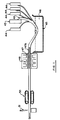
- Figure 1 is a schematic side elevational view of a pultrusion system according to the invention.
- Figure 2 is a cross sectional view of a sealed window unit incorporating a spacer according to the invention.
- Figure 3 is a cross sectional view of a spacer according to the invention on an enlarged scale and of a different type from the spacer shown in Figure 2.
- Figure 4 is a cross-sectional view of a further spacer according to the invention.
- a sealed window unit is a conventional item and as well known comprises a pair of panes 10 and 11 which lie parallel and are spaced at their side edges by spacers generally indicated at 12.
- Each of the spacers comprises an elongate body which is cut to length and joined at corners to form a frame system which fits inside the panes at the edges of the panes to the hold the panes in the required spaced position.
- the spacer is of the type which uses a double sealing system including a first portion of sealant 21 along the sides of the spacer and a second sealant 22 at the outer surface of the spacer. A covering layer of a further sealing material is applied at 23. To accommodate the sealant material 21, each of the side surfaces is slightly recessed.
- FIG. 3 A second type of spacer element is shown in Figure 3 in which the side surfaces 25 and 26 are substantially flat and a bottom surface 27 includes a pair of inclined portions 28 and 29 which extend downwardly toward a lowermost portion 30 thus defining a larger area for receiving the additional amount of sealing material around the edge to make up for the absence of sealing material at the sides.
- the spacer element has a top surface 31, the sides 25 and 26 and a bottom surface 27.
- the spacer shown in Figure 2 is of a similar configuration although as described above the design is slightly different.
- the four surfaces surround a hollow interior 32 which can be filled with a desicant as indicated at 33 in Figure 2.
- the spacer element is modified in two ways. Firstly the spacer element is formed so it includes embedded within the element a layer 40 consisting of a foil layer 41 and a mat layer 42.
- the layer 40 is supplied to the pultrusion process on a supply reel 43 and in addition to the pultrusion process is supplied a plurality of rovings on reels or spools 44.
- the supply material is collated into a bundle of material which is dipped into a bath 45 of a suitable thermosetting resin 46 so that the bundle or collation of the fiber elements or structures is impregnated with the thermosetting resin.
- the impregnated bundle is then fed into a die 46 which has a mandrel 47 so that the die and mandrel cooperate to shape the spacer into the four sides and the hollow interior described above.
- the die includes heating elements 48 which set the thermosetting material into the required shape while the material is held in the shape by the elongate die. Downstream of the die the set part is pulled from the die by a pulling system indicated at 50 and is subsequently cut to required lengths by a cutting system 51.
- the layer 40 comprises a continuous tape or strip of material carrying foil on one side and a fibrous mat on the other side adhesively attached to the foil.
- the mat comprises bi-directional fibers preferably of glass and generally in nonwoven form although other forms may be possible.
- the width of the layer 40 is chosen so that it takes up the position shown in Figures 2 and 3 that is it extends from one end at a position at a mid-height of the side wall 25, across the bottom wall 27 and to a position mid-height of the side wall 26.
- the layer is continuous from one edge to the other edge.
- the foil portion of the layer is impervious to moisture or moisture vapour so that the lower portion of this spacer as shown in Figure 3 is substantially totally impervious to moisture vapour transmission.
- the layer is formed in the pultrusion process so that the foil is covered on both surfaces by the fiber reinforcements.
- One side of the layer carries the mat which may or may not be covered by further layers of roving and the other layer of the foil is covered by the layers of roving so the foil is held away from the inner surface of the die and is fully embedded within the part when the part is complete.
- the control of the rovings and the layer as they are fed toward the die so that the required positioning is obtained is well known to one skilled in the art and can be properly controlled so that the layer remains continuously at the buried position throughout the continuous manufacture of the spacer element.
- the thickness of the walls of the element are arranged such that the thickness at the position containing the layer 40 is greater than the thickness at the remaining part.
- the thickness of the upper wall 31 may be of the order of 0.055 inches and the thickness of the part containing the layer 40 may be of the order of 0.070 inches.
- This design of the part has two advantages. Firstly the reduction in thickness of the upper wall 31 allows that wall to have an increased permeability to moisture vapour so that it is no longer necessary to provide a slot or other apertures in the upper wall to allow the moisture vapour in the area between the panes to reach the desicant. This moisture vapour can therefore be transmitted directly through the upper wall 31 and is gradually over time removed by the desicant 33.
- the advantage in the design of the part by which the upper wall 31 is reduced in thickness allows the part to have an equalized drag on the die as it passes through the die.
- the layer 40 tends to increase the drag as it is passed through the die and it is necessary therefore to modify the remainder of the parts so that the drag is substantially equalized. This is obtained by reducing the thickness of the upper wall so that the forces on the upper wall are increased as it is formed thus increasing drag.
- the part can then be formed without a tendency to bow as it is passed through the die.
- the manufacture of the spacer element without the necessity for a central slot for communication of the moisture vapour to the desicant allows the element to be manufactured with thinner wall structure thus reducing the amount of material and accordingly the cost.
- the element as shown in Figure 3 is formed substantially wholly from the thermosetting resin which is reinforced solely by roving material which is uni-directional and by the layer 40.
- FIG 4 this figure is similar to Figure 3 in that it includes a spacer as described indicated at 50 which has the moisture permeable layer 51 embedded during the manufacturing technique as previously described.
- the layer is carefully inserted into the body of the spacer so that it approaches as closely as possible or reaches the outer surface 52 of the spacer at the sides of the spacer.
- the outermost edge of the layer indicated at 53 lies in or contacts the surface 52 so that the moisture impermeability extends from one side edge of the spacer to the opposed side edge without any path of permeability along the sides of the spacer.
- the layer generally indicated at 51 is modified in that it comprises a three part laminate defined by three layers 54, 55 and 56.
- the central layer 55 is formed of the foil material to provide the moisture impermeability.
- This layer is arranged to be as thin as possible so that the layer itself does not define sufficient strength to undergo the processing.
- the layer is supported by the laminated covering layers 54 and 56 each of which covers a respective side of the foil.
- the laminating layers provide the necessary strength for the product to undergo the processing in the manufacture of the spacer. Thus they act as supporting layers to carry the material into the part.
- the laminating layers 54 and 56 act to bond the foil layer into the part.
- the laminating layers in one example can be provided by a resin which is compatible with the thermosetting resin of which the part is manufactured.
- the layer is of a type which bonds during the heat processing to the thermosetting resin.
- One example is the use of polyester for the layers and a similar polyester for the thermosetting resin so that bonding automatically takes place to reduce the risk of delamination during use
- the supporting layers can be formed of a paper material which has sufficient strength to transport the foil into the process and at the same time provides bonding with the resin by the infiltration of the resin into the interstices of the layer.
Landscapes
- Engineering & Computer Science (AREA)
- Civil Engineering (AREA)
- Structural Engineering (AREA)
- Chemical & Material Sciences (AREA)
- Composite Materials (AREA)
- Mechanical Engineering (AREA)
- Laminated Bodies (AREA)
- Securing Of Glass Panes Or The Like (AREA)
- Joining Of Glass To Other Materials (AREA)
- Extrusion Moulding Of Plastics Or The Like (AREA)
- Liquid Crystal (AREA)
- Casings For Electric Apparatus (AREA)
- Window Of Vehicle (AREA)
Claims (3)
- Abstandhalterprofil für Isolierglas-Fenstereinheit mit einem langgestreckten Körper (12) mit zwei beabstandeten Seitenflächen (25, 26), die jeweils derart an eine Glasscheibe anlegbar sind, daß die Glasscheiben in der Isolierglass-Fenstereinheit auf Abstand gehalten werden, mit einer Oberseite (31), die von einer Kante der Fenstereinheit aus einwärts gewandt ist, einer Unterseite (27), die von einer Kante der Fenstereinheit aus auswärts gewandt ist, und einem von den Seitenflächen, der Ober- und der Unterseite umgebenen hohlen Innenraum (32), und mit einer in der Oberseite (31) enthaltenen Einrichtung, die einen Durchgang von Feuchtigkeit durch die Oberseite zum hohlen Innenraum zuläßt, wobei das Abstandhalterprofil aus einem Harzmaterial (46) besteht und eine Sperrschicht (41) aus einem für Feuchtigkeit undurchlässigen Material enthalt, die in das Harzmaterial (46) so eingebettet ist, daß sie kontinuierlich in Längsrichtung des Abstandhalterprofils (12) und kontinuierlich von einer Stelle in der Seitenfläche (25) abwärts, quer über die Unterseite (27) und zu einer Stelle entlang der anderen Seitenfläche (26) verlaüft, dadurch gekennzeichnet, daß das Abstandhalterprofil (23) durch Zieh-Strangpressen hergestellt ist, daß das Harzmaterial (46) ein wärmehärtendes Material ist und eine Vielzahl langgestreckter Faserelemente (43, 44) enthält, die stetig in Längsrichtung des langgestreckter Körpers verlaufen, daß die Sperrschicht (40) auf beiden Seiten von dem wärmehärtenden Harz (46) und dem Fasermaterial (43, 44) abgedeckt ist, daß die Sperrschicht (40, 51) sowie eine zweite Schicht eines stützenden Materials (42, 54) auf einer Seite der ersten Schicht an dieser festgelegt sind und daß das stützende Material solcher Art ist, daß es eine wirksame Bindung mit dem wärmehärtenden Harz (46) bietet, um ein Delaminieren des Körpers an der Sperrschicht zu verhindern.
- Abstandhalterprofil nach Anspruch 1, dadurch gekennzeichnet, daß die Sperrschicht eine dritte Schicht (56) aufweist, die auf der der einen entgegengesetzten Seite der ersten Schicht auf dieser festgelegt ist, und daß die dritte Schicht aus einem stützenden Material solcher Art gebildet ist, daß die erste Schicht abgestützt und eine wirksame Bindung zum wärmehärtenden Harz hergestellt wird, um ein Delaminieren des Körpers an der Sperrschicht zu verhindern.
- Abstandhalterprofil nach Anspruch 1, dadurch gekennzeichnet, daß die Oberseite (31) in einer zu ihr rechtwinkligen Richtung eine Wanddicke aufweist, die geringer als die Wanddicke der Unterseite (27) ist.
Applications Claiming Priority (4)
| Application Number | Priority Date | Filing Date | Title |
|---|---|---|---|
| US37469289A | 1989-07-03 | 1989-07-03 | |
| US374692 | 1989-07-03 | ||
| US07/441,143 US5079054A (en) | 1989-07-03 | 1989-11-27 | Moisture impermeable spacer for a sealed window unit |
| US441143 | 1989-11-27 |
Publications (2)
| Publication Number | Publication Date |
|---|---|
| EP0480951A1 EP0480951A1 (de) | 1992-04-22 |
| EP0480951B1 true EP0480951B1 (de) | 1993-09-29 |
Family
ID=27006716
Family Applications (1)
| Application Number | Title | Priority Date | Filing Date |
|---|---|---|---|
| EP90909599A Expired - Lifetime EP0480951B1 (de) | 1989-07-03 | 1990-07-03 | Feuchtigkeitsundurchlässiges abstandhalterprofil für isolierglas |
Country Status (9)
| Country | Link |
|---|---|
| US (1) | US5079054A (de) |
| EP (1) | EP0480951B1 (de) |
| AT (1) | ATE95274T1 (de) |
| AU (1) | AU5854690A (de) |
| CA (1) | CA2058945C (de) |
| DE (1) | DE69003682T2 (de) |
| DK (1) | DK0480951T3 (de) |
| ES (1) | ES2048494T3 (de) |
| WO (1) | WO1991000409A1 (de) |
Cited By (5)
| Publication number | Priority date | Publication date | Assignee | Title |
|---|---|---|---|---|
| US7875675B2 (en) | 2005-11-23 | 2011-01-25 | Milgard Manufacturing Incorporated | Resin for composite structures |
| US7901762B2 (en) | 2005-11-23 | 2011-03-08 | Milgard Manufacturing Incorporated | Pultruded component |
| US8101107B2 (en) | 2005-11-23 | 2012-01-24 | Milgard Manufacturing Incorporated | Method for producing pultruded components |
| CN102468635A (zh) * | 2010-11-10 | 2012-05-23 | 江苏源盛复合材料技术股份有限公司 | 输电线路用间隔棒制备工艺 |
| US8597016B2 (en) | 2005-11-23 | 2013-12-03 | Milgard Manufacturing Incorporated | System for producing pultruded components |
Families Citing this family (63)
| Publication number | Priority date | Publication date | Assignee | Title |
|---|---|---|---|---|
| US5290611A (en) * | 1989-06-14 | 1994-03-01 | Taylor Donald M | Insulative spacer/seal system |
| US5302425A (en) * | 1989-06-14 | 1994-04-12 | Taylor Donald M | Ribbon type spacer/seal system |
| US5675944A (en) * | 1990-09-04 | 1997-10-14 | P.P.G. Industries, Inc. | Low thermal conducting spacer assembly for an insulating glazing unit and method of making same |
| CA2049703C (en) * | 1990-09-04 | 1995-01-17 | Robert B. Hodek | Low thermal conducting spacer assembly for an insulating glazing unit and method of making same |
| CA2131918A1 (en) * | 1992-05-18 | 1993-11-25 | Charles D. Newby | Metal-polymer composite insulative spacer for glass members and insulative window containing same |
| US5512341A (en) * | 1992-05-18 | 1996-04-30 | Crane Plastics Company Limited Partnership | Metal-polymer composite insulative spacer for glass members and insulative window containing same |
| DE9303795U1 (de) * | 1993-03-16 | 1994-07-14 | Roller, Ulrike, 71111 Waldenbuch | Abstandshalter |
| ATE152499T1 (de) * | 1992-12-10 | 1997-05-15 | Thermix Gmbh Isolationssysteme | Abstandhalter |
| DE4300481A1 (de) * | 1993-01-11 | 1994-07-14 | Kunert Heinz | Rahmenlose Isolierverglasung und Verfahren zu deren Herstellung |
| WO1995020713A1 (en) * | 1994-01-26 | 1995-08-03 | Hygrade Metal Moulding Manufacturing Corp. | Warm edge spacer bars |
| US5640828A (en) * | 1995-02-15 | 1997-06-24 | Weather Shield Mfg., Inc. | Spacer for an insulated window panel assembly |
| DE19525263A1 (de) * | 1995-07-11 | 1997-03-06 | Ver Glaswerke Gmbh | Feuerwiderstandsfähige Verglasung |
| DE19525735A1 (de) * | 1995-07-14 | 1997-01-16 | Huels Chemische Werke Ag | Abstandhalter für Isolierverglasungen |
| US5962090A (en) * | 1995-09-12 | 1999-10-05 | Saint-Gobain Vitrage Suisse Ag | Spacer for an insulating glazing assembly |
| DE19881385D2 (de) * | 1997-09-25 | 2000-07-13 | Caprano & Brunnhofer | Abstandhalterprofil für Isolierscheibeneinheit |
| DE19805348A1 (de) * | 1998-02-11 | 1999-08-12 | Caprano & Brunnhofer | Abstandhalterprofil für Isolierscheibeneinheit |
| DE19807454A1 (de) * | 1998-02-21 | 1999-08-26 | Ensinger | Abstandhalter |
| CA2269110A1 (en) * | 1998-04-27 | 1999-10-27 | Flachglas Aktiengesellschaft | Spacing profile for double-glazing unit |
| DE29807418U1 (de) * | 1998-04-27 | 1999-06-24 | Flachglas AG, 90766 Fürth | Abstandhalterprofil für Isolierscheibeneinheit |
| DE60019994T2 (de) * | 1999-03-08 | 2006-01-19 | The Procter & Gamble Company, Cincinnati | Absorbierende und flexible Struktur mit Stärkefasern |
| US6734809B1 (en) * | 1999-04-02 | 2004-05-11 | Think Outside, Inc. | Foldable keyboard |
| US20020123288A1 (en) * | 1999-06-21 | 2002-09-05 | Pella Corporation | Pultruded part with reinforcing mat |
| US6872273B2 (en) * | 1999-06-21 | 2005-03-29 | Pella Corporation | Method of making a pultruded part with a reinforcing mat |
| US6881288B2 (en) * | 1999-06-21 | 2005-04-19 | Pella Corporation | Method of making a reinforcing mat for a pultruded part |
| ATE330103T1 (de) * | 1999-10-11 | 2006-07-15 | Nordicon Develop Aps | Isolierglaseinheit mit abstandhalter mit gasdichter lippendichtung |
| FR2807783B1 (fr) * | 2000-04-13 | 2002-12-20 | Saint Gobain Vitrage | Vitrage isolant et son procede de fabrication |
| US7514135B2 (en) * | 2001-06-14 | 2009-04-07 | Omniglass Ltd. | Pultruded part reinforced by longitudinal and transverse fibers and a method of manufacturing thereof |
| US20030003265A1 (en) * | 2001-06-14 | 2003-01-02 | Davies Laurence W. | Pultruded part reinforced by longitudinal and transverse fibers and a method of manufacturing thereof |
| KR20020095826A (ko) * | 2001-06-16 | 2002-12-28 | 김춘만 | 이중유리 제조용 스페이서 |
| US6989188B2 (en) | 2003-11-07 | 2006-01-24 | Technoform Caprano Und Brunnhofer Gmbh & Co. Kd | Spacer profiles for double glazings |
| CN1914399B (zh) * | 2004-01-09 | 2011-04-20 | 纤维线公司 | 一种建筑或者窗户构件以及建造建筑物的方法 |
| DE202005019973U1 (de) * | 2004-09-09 | 2006-04-06 | Technoform Caprano Und Brunnhofer Gmbh & Co. Kg | Abstandshalterprofil für einen Abstandshalterrahmen für eine Isolierscheibeneinheit und Isolierscheibeneinheit |
| US9309714B2 (en) | 2007-11-13 | 2016-04-12 | Guardian Ig, Llc | Rotating spacer applicator for window assembly |
| KR20100097154A (ko) | 2007-11-13 | 2010-09-02 | 인피니트 에지 테크놀로지, 엘엘씨 | 밀폐 유닛 및 스페이서 |
| DE102008033249A1 (de) * | 2008-07-15 | 2010-01-21 | Gssg Holding Gmbh & Co. Kg | Isolierglasscheibe |
| WO2011008860A1 (en) * | 2009-07-14 | 2011-01-20 | Infinite Edge Technologies, Llc | Stretched strips for spacer and sealed unit |
| DE102010006127A1 (de) * | 2010-01-29 | 2011-08-04 | Technoform Glass Insulation Holding GmbH, 34277 | Abstandshalterprofil mit Verstärkungsschicht |
| EP2580418B1 (de) | 2010-06-10 | 2014-08-13 | Guardian IG, LLC | Fensterabstandhalteraufträger |
| DE102010049806A1 (de) * | 2010-10-27 | 2012-05-03 | Technoform Glass Insulation Holding Gmbh | Abstandshalterprofil und Isolierscheibeneinheit mit einem solchen Abstandshalterprofil |
| US9228389B2 (en) | 2010-12-17 | 2016-01-05 | Guardian Ig, Llc | Triple pane window spacer, window assembly and methods for manufacturing same |
| DE102011009359A1 (de) | 2011-01-25 | 2012-07-26 | Technoform Glass Insulation Holding Gmbh | Abstandshalterprofil und Isolierscheibeneinheit mit einem solchen Abstandshalterprofil |
| US8871316B2 (en) | 2011-05-31 | 2014-10-28 | Guardian Industries Corp. | Insulated glass (IG) units including spacer systems, and/or methods of making the same |
| DE202012013283U1 (de) * | 2012-01-13 | 2015-11-23 | Saint-Gobain Glass France | Abstandshalter für Isolierverglasungen |
| EP2626496A1 (de) | 2012-02-10 | 2013-08-14 | Technoform Glass Insulation Holding GmbH | Abstandhalterprofil für einen Abstandhalterrahmen für eine Isolierfenstereinheit mit Zwischenraumelementen und Isolierfenstereinheit |
| US9689196B2 (en) | 2012-10-22 | 2017-06-27 | Guardian Ig, Llc | Assembly equipment line and method for windows |
| US9260907B2 (en) | 2012-10-22 | 2016-02-16 | Guardian Ig, Llc | Triple pane window spacer having a sunken intermediate pane |
| US8789343B2 (en) | 2012-12-13 | 2014-07-29 | Cardinal Ig Company | Glazing unit spacer technology |
| USD736594S1 (en) | 2012-12-13 | 2015-08-18 | Cardinal Ig Company | Spacer for a multi-pane glazing unit |
| DK3052731T4 (da) * | 2013-09-30 | 2024-07-29 | Saint Gobain | Afstandsstykke til isolerende rudeenheder |
| WO2015086457A2 (de) | 2013-12-12 | 2015-06-18 | Saint-Gobain Glass France | Isolierverglasung mit verbesserter abdichtung |
| KR20160095129A (ko) | 2013-12-12 | 2016-08-10 | 쌩-고벵 글래스 프랑스 | 압출된 프로파일링된 밀봉체를 포함하는, 절연 글레이징 유닛용 스페이서 |
| EP3161237B1 (de) | 2014-06-27 | 2018-07-25 | Saint-Gobain Glass France | Isolierverglasung mit abstandhalter und verfahren zur herstellung einer solchen sowie deren verwendung als gebäudeverglasung |
| US10301868B2 (en) | 2014-06-27 | 2019-05-28 | Saint-Gobain Glass France | Insulated glazing comprising a spacer, and production method |
| CN106715819B (zh) | 2014-09-25 | 2019-08-13 | 法国圣戈班玻璃厂 | 用于隔热装配玻璃的间隔件 |
| NZ735595A (en) | 2015-03-02 | 2022-04-29 | Saint Gobain | Foamed spacer for insulated glazing unit |
| USD777345S1 (en) | 2015-05-21 | 2017-01-24 | Saint-Gobain Glass France | Spacer bar |
| DE102015122714A1 (de) * | 2015-12-23 | 2017-07-27 | Ensinger Gmbh | Abstandhalter für Isolierglasscheiben |
| US10675844B2 (en) * | 2016-03-31 | 2020-06-09 | Panasonic Intellectual Property Management Co., Ltd. | Glass panel unit and building component including the same |
| CA2988888C (en) * | 2016-12-16 | 2019-10-15 | Pella Corporation | Reserve cladding biasing |
| DE102017005296A1 (de) * | 2017-05-24 | 2018-11-29 | Thomas Gmbh + Co. Technik + Innovation Kg | Verfahren und Vorrichtung zur Herstellung eines Kunststoffprofils |
| DE102019121690A1 (de) * | 2019-08-12 | 2021-02-18 | Ensinger Gmbh | Abstandhalter für Isolierglasscheiben |
| EP4347981A1 (de) * | 2021-05-31 | 2024-04-10 | Saint-Gobain Glass France | Abstandhalter mit co-extrudiertem hohlprofil |
| CA3240032A1 (en) | 2022-04-14 | 2023-10-19 | Nikolai BORCHMANN | Spacer with improved mechanical stiffness |
Family Cites Families (12)
| Publication number | Priority date | Publication date | Assignee | Title |
|---|---|---|---|---|
| DE1924110A1 (de) * | 1969-05-12 | 1971-05-13 | Licentia Gmbh | Verfahren zum Herstellen von Mehrschichtstoffen aus harzimpraegnierten Lagen |
| US4015394A (en) * | 1975-10-14 | 1977-04-05 | Gerald Kessler | Double-insulated glass window with insulating spacer |
| DE2913876A1 (de) * | 1979-04-06 | 1980-10-16 | Fibercast Gmbh | Waermegedaemmtes rohr und verfahren zu seiner herstellung |
| DE3373690D1 (en) * | 1982-12-08 | 1987-10-22 | Omniglass Ltd | A spacer strip for a sealed window unit and a method for manufacture of the strip |
| US4564540A (en) * | 1982-12-08 | 1986-01-14 | Davies Lawrence W | Pultruded fibreglass spacer for sealed window units |
| DE3302659A1 (de) * | 1983-01-27 | 1984-08-02 | Reichstadt, Hans Udo, 5628 Heiligenhaus | Abstandhalteprofil fuer mehrscheiben-isolierglas |
| AU3581784A (en) * | 1984-01-16 | 1985-07-25 | Budd Company, The | Fiber-reinforced pultrusion |
| GB2162228B (en) * | 1984-07-25 | 1987-07-15 | Sanden Corp | Double-glazed window for a refrigerator |
| US4788088A (en) * | 1985-10-04 | 1988-11-29 | Kohl John O | Apparatus and method of making a reinforced plastic laminate structure and products resulting therefrom |
| CA1285177C (en) * | 1986-09-22 | 1991-06-25 | Michael Glover | Multiple pane sealed glazing unit |
| US4745711A (en) * | 1986-10-16 | 1988-05-24 | Tremco Incorporated | Selectively permeable zeolite adsorbents and sealants made therefrom |
| AT390658B (de) * | 1987-03-10 | 1990-06-11 | Fischer Gmbh | Rohrleitung fuer ein triebwerk |
-
1989
- 1989-11-27 US US07/441,143 patent/US5079054A/en not_active Expired - Lifetime
-
1990
- 1990-07-03 ES ES90909599T patent/ES2048494T3/es not_active Expired - Lifetime
- 1990-07-03 WO PCT/CA1990/000209 patent/WO1991000409A1/en not_active Ceased
- 1990-07-03 EP EP90909599A patent/EP0480951B1/de not_active Expired - Lifetime
- 1990-07-03 AU AU58546/90A patent/AU5854690A/en not_active Abandoned
- 1990-07-03 CA CA002058945A patent/CA2058945C/en not_active Expired - Lifetime
- 1990-07-03 DK DK90909599.4T patent/DK0480951T3/da active
- 1990-07-03 DE DE90909599T patent/DE69003682T2/de not_active Expired - Fee Related
- 1990-07-03 AT AT90909599T patent/ATE95274T1/de active
Cited By (7)
| Publication number | Priority date | Publication date | Assignee | Title |
|---|---|---|---|---|
| US7875675B2 (en) | 2005-11-23 | 2011-01-25 | Milgard Manufacturing Incorporated | Resin for composite structures |
| US7901762B2 (en) | 2005-11-23 | 2011-03-08 | Milgard Manufacturing Incorporated | Pultruded component |
| US8101107B2 (en) | 2005-11-23 | 2012-01-24 | Milgard Manufacturing Incorporated | Method for producing pultruded components |
| US8519050B2 (en) | 2005-11-23 | 2013-08-27 | Milgard Manufacturing Incorporated | Resin for composite structures |
| US8597016B2 (en) | 2005-11-23 | 2013-12-03 | Milgard Manufacturing Incorporated | System for producing pultruded components |
| CN102468635A (zh) * | 2010-11-10 | 2012-05-23 | 江苏源盛复合材料技术股份有限公司 | 输电线路用间隔棒制备工艺 |
| CN102468635B (zh) * | 2010-11-10 | 2014-08-06 | 江苏源盛复合材料技术股份有限公司 | 输电线路用间隔棒制备工艺 |
Also Published As
| Publication number | Publication date |
|---|---|
| CA2058945C (en) | 1995-01-03 |
| ATE95274T1 (de) | 1993-10-15 |
| DE69003682T2 (de) | 1994-05-05 |
| DE69003682D1 (de) | 1993-11-04 |
| WO1991000409A1 (en) | 1991-01-10 |
| DK0480951T3 (da) | 1994-03-14 |
| CA2058945A1 (en) | 1991-01-04 |
| US5079054A (en) | 1992-01-07 |
| AU5854690A (en) | 1991-01-17 |
| ES2048494T3 (es) | 1994-03-16 |
| EP0480951A1 (de) | 1992-04-22 |
Similar Documents
| Publication | Publication Date | Title |
|---|---|---|
| US5079054A (en) | Moisture impermeable spacer for a sealed window unit | |
| KR100768503B1 (ko) | 단열 창유리 유닛, 상기 유닛의 제조방법 및 프로파일을 갖는 스트립 | |
| JP2534466B2 (ja) | 熱回復性物品の製造方法 | |
| US5094055A (en) | Window glass seal | |
| US4389447A (en) | Dimensionally stable composite material and process for the manufacture thereof | |
| GB2059873A (en) | Laminated cable sleeve liner | |
| US4428995A (en) | Glass cloth and prepreg containing same | |
| CN111936717A (zh) | 具有加强元件的间距保持件 | |
| GB2083532A (en) | Weatherstrip | |
| CA1153680A (en) | Sheet useful as roofing | |
| US20240199231A1 (en) | Method for manufacuturing an aircraft window frame comprising a barrier layer, window frame obtained from this method and aircraft comprising at least one such window frame | |
| EP0553414B1 (de) | Plattenförmiges Element aus Kunstharz | |
| FR2537502B1 (fr) | Materiau composite comprenant une ossature formee d'une nappe tissee, impregnee de matiere plastique et pourvue d'au moins une couche de revetement exterieur | |
| CN100377870C (zh) | 包含一层纵向高韧性纱线的加强带 | |
| US3074832A (en) | Plastic window plate structure and method of making same | |
| EP0556384A1 (de) | Mit schmelzklebstoff beschichtetem garn verstärkter film und verfahren zu dessen herstellung | |
| FR2560819A1 (fr) | Panneau composite et procede concu pour la fabrication de ce panneau | |
| EP0038091A1 (de) | Energieabsorbierende Konstruktion, insbes. für Skis | |
| CA1062595A (en) | Process for the production of a glass fibre-reinforced polyester resin laminate structure | |
| CA2064447C (en) | Moisture impermeable spacer for a sealed window unit | |
| WO1982001735A1 (en) | A weather strip and a reinforcing layer for use in making the same | |
| EP0828600A1 (de) | Wärmeschrumpfbarer gegenstand | |
| JP3117504B2 (ja) | 繊維複合雨樋の製造方法 | |
| US3037894A (en) | Reinforced building board | |
| CA2188401A1 (en) | Terry-cloth fabric panels |
Legal Events
| Date | Code | Title | Description |
|---|---|---|---|
| PUAI | Public reference made under article 153(3) epc to a published international application that has entered the european phase |
Free format text: ORIGINAL CODE: 0009012 |
|
| 17P | Request for examination filed |
Effective date: 19920131 |
|
| AK | Designated contracting states |
Kind code of ref document: A1 Designated state(s): AT BE CH DE DK ES FR GB IT LI LU NL SE |
|
| 17Q | First examination report despatched |
Effective date: 19920630 |
|
| GRAA | (expected) grant |
Free format text: ORIGINAL CODE: 0009210 |
|
| AK | Designated contracting states |
Kind code of ref document: B1 Designated state(s): AT BE CH DE DK ES FR GB IT LI LU NL SE |
|
| PG25 | Lapsed in a contracting state [announced via postgrant information from national office to epo] |
Ref country code: LI Effective date: 19930929 Ref country code: CH Effective date: 19930929 |
|
| REF | Corresponds to: |
Ref document number: 95274 Country of ref document: AT Date of ref document: 19931015 Kind code of ref document: T |
|
| REF | Corresponds to: |
Ref document number: 69003682 Country of ref document: DE Date of ref document: 19931104 |
|
| ITF | It: translation for a ep patent filed | ||
| REG | Reference to a national code |
Ref country code: CH Ref legal event code: PL |
|
| ET | Fr: translation filed | ||
| REG | Reference to a national code |
Ref country code: DK Ref legal event code: T3 |
|
| REG | Reference to a national code |
Ref country code: ES Ref legal event code: FG2A Ref document number: 2048494 Country of ref document: ES Kind code of ref document: T3 |
|
| PLBE | No opposition filed within time limit |
Free format text: ORIGINAL CODE: 0009261 |
|
| STAA | Information on the status of an ep patent application or granted ep patent |
Free format text: STATUS: NO OPPOSITION FILED WITHIN TIME LIMIT |
|
| PG25 | Lapsed in a contracting state [announced via postgrant information from national office to epo] |
Ref country code: LU Free format text: LAPSE BECAUSE OF NON-PAYMENT OF DUE FEES Effective date: 19940731 |
|
| 26N | No opposition filed | ||
| EAL | Se: european patent in force in sweden |
Ref document number: 90909599.4 |
|
| PGFP | Annual fee paid to national office [announced via postgrant information from national office to epo] |
Ref country code: GB Payment date: 19950627 Year of fee payment: 6 |
|
| PGFP | Annual fee paid to national office [announced via postgrant information from national office to epo] |
Ref country code: SE Payment date: 19950628 Year of fee payment: 6 |
|
| PGFP | Annual fee paid to national office [announced via postgrant information from national office to epo] |
Ref country code: BE Payment date: 19950630 Year of fee payment: 6 |
|
| PGFP | Annual fee paid to national office [announced via postgrant information from national office to epo] |
Ref country code: ES Payment date: 19950717 Year of fee payment: 6 |
|
| PGFP | Annual fee paid to national office [announced via postgrant information from national office to epo] |
Ref country code: AT Payment date: 19950731 Year of fee payment: 6 |
|
| PGFP | Annual fee paid to national office [announced via postgrant information from national office to epo] |
Ref country code: DE Payment date: 19950811 Year of fee payment: 6 |
|
| PGFP | Annual fee paid to national office [announced via postgrant information from national office to epo] |
Ref country code: DK Payment date: 19950823 Year of fee payment: 6 |
|
| PGFP | Annual fee paid to national office [announced via postgrant information from national office to epo] |
Ref country code: FR Payment date: 19950828 Year of fee payment: 6 |
|
| PGFP | Annual fee paid to national office [announced via postgrant information from national office to epo] |
Ref country code: NL Payment date: 19950831 Year of fee payment: 6 |
|
| PG25 | Lapsed in a contracting state [announced via postgrant information from national office to epo] |
Ref country code: GB Effective date: 19960703 Ref country code: DK Effective date: 19960703 Ref country code: AT Effective date: 19960703 |
|
| REG | Reference to a national code |
Ref country code: DK Ref legal event code: EBP |
|
| PG25 | Lapsed in a contracting state [announced via postgrant information from national office to epo] |
Ref country code: SE Effective date: 19960704 Ref country code: ES Free format text: LAPSE BECAUSE OF EXPIRATION OF PROTECTION Effective date: 19960704 |
|
| PG25 | Lapsed in a contracting state [announced via postgrant information from national office to epo] |
Ref country code: BE Effective date: 19960731 |
|
| BERE | Be: lapsed |
Owner name: OMNIGLASS LTD Effective date: 19960731 |
|
| PG25 | Lapsed in a contracting state [announced via postgrant information from national office to epo] |
Ref country code: NL Effective date: 19970201 |
|
| GBPC | Gb: european patent ceased through non-payment of renewal fee |
Effective date: 19960703 |
|
| PG25 | Lapsed in a contracting state [announced via postgrant information from national office to epo] |
Ref country code: FR Effective date: 19970328 |
|
| NLV4 | Nl: lapsed or anulled due to non-payment of the annual fee |
Effective date: 19970201 |
|
| PG25 | Lapsed in a contracting state [announced via postgrant information from national office to epo] |
Ref country code: DE Effective date: 19970402 |
|
| EUG | Se: european patent has lapsed |
Ref document number: 90909599.4 |
|
| REG | Reference to a national code |
Ref country code: FR Ref legal event code: ST |
|
| REG | Reference to a national code |
Ref country code: ES Ref legal event code: FD2A Effective date: 19990601 |
|
| PG25 | Lapsed in a contracting state [announced via postgrant information from national office to epo] |
Ref country code: IT Free format text: LAPSE BECAUSE OF NON-PAYMENT OF DUE FEES;WARNING: LAPSES OF ITALIAN PATENTS WITH EFFECTIVE DATE BEFORE 2007 MAY HAVE OCCURRED AT ANY TIME BEFORE 2007. THE CORRECT EFFECTIVE DATE MAY BE DIFFERENT FROM THE ONE RECORDED. Effective date: 20050703 |