EP0479650A1 - Clapet de sécurité pour circuit de fluide - Google Patents
Clapet de sécurité pour circuit de fluide Download PDFInfo
- Publication number
- EP0479650A1 EP0479650A1 EP91402572A EP91402572A EP0479650A1 EP 0479650 A1 EP0479650 A1 EP 0479650A1 EP 91402572 A EP91402572 A EP 91402572A EP 91402572 A EP91402572 A EP 91402572A EP 0479650 A1 EP0479650 A1 EP 0479650A1
- Authority
- EP
- European Patent Office
- Prior art keywords
- valve body
- nut
- cylindrical part
- valve
- solenoid winding
- Prior art date
- Legal status (The legal status is an assumption and is not a legal conclusion. Google has not performed a legal analysis and makes no representation as to the accuracy of the status listed.)
- Withdrawn
Links
Images

Classifications
-
- F—MECHANICAL ENGINEERING; LIGHTING; HEATING; WEAPONS; BLASTING
- F16—ENGINEERING ELEMENTS AND UNITS; GENERAL MEASURES FOR PRODUCING AND MAINTAINING EFFECTIVE FUNCTIONING OF MACHINES OR INSTALLATIONS; THERMAL INSULATION IN GENERAL
- F16K—VALVES; TAPS; COCKS; ACTUATING-FLOATS; DEVICES FOR VENTING OR AERATING
- F16K31/00—Actuating devices; Operating means; Releasing devices
- F16K31/02—Actuating devices; Operating means; Releasing devices electric; magnetic
- F16K31/06—Actuating devices; Operating means; Releasing devices electric; magnetic using a magnet, e.g. diaphragm valves, cutting off by means of a liquid
- F16K31/0675—Electromagnet aspects, e.g. electric supply therefor
-
- F—MECHANICAL ENGINEERING; LIGHTING; HEATING; WEAPONS; BLASTING
- F16—ENGINEERING ELEMENTS AND UNITS; GENERAL MEASURES FOR PRODUCING AND MAINTAINING EFFECTIVE FUNCTIONING OF MACHINES OR INSTALLATIONS; THERMAL INSULATION IN GENERAL
- F16K—VALVES; TAPS; COCKS; ACTUATING-FLOATS; DEVICES FOR VENTING OR AERATING
- F16K31/00—Actuating devices; Operating means; Releasing devices
- F16K31/02—Actuating devices; Operating means; Releasing devices electric; magnetic
- F16K31/06—Actuating devices; Operating means; Releasing devices electric; magnetic using a magnet, e.g. diaphragm valves, cutting off by means of a liquid
-
- Y—GENERAL TAGGING OF NEW TECHNOLOGICAL DEVELOPMENTS; GENERAL TAGGING OF CROSS-SECTIONAL TECHNOLOGIES SPANNING OVER SEVERAL SECTIONS OF THE IPC; TECHNICAL SUBJECTS COVERED BY FORMER USPC CROSS-REFERENCE ART COLLECTIONS [XRACs] AND DIGESTS
- Y10—TECHNICAL SUBJECTS COVERED BY FORMER USPC
- Y10T—TECHNICAL SUBJECTS COVERED BY FORMER US CLASSIFICATION
- Y10T137/00—Fluid handling
- Y10T137/5109—Convertible
Definitions
- Some of these safety valves have an electrical position control allowing the passage of the fluid by opening the valve. Breakdowns can occur on this electrical control, and / or on the mechanical parts which are coupled to it, and it has already been planned to remedy, at least temporarily, these failures, by means of a voluntary command to open the valve, implementation at the will of a user.
- a nut maintains the solenoid winding of the electro-control device for the passage of fluid in the assembled position on the body of the valve, and has a bottom, crossed by a screw arranged opposite the core of said electromagnet. In the event of a possible breakdown, during which the electromagnet no longer controls the opening of the valve, it suffices to turn said screw until it pushes the valve back into its open position.
- the invention intends to remedy this state of affairs by isolating the internal mechanism from external humidity, this permanently except possibly temporarily during the implementation of the voluntary emergency command to open the valve.
- the invention therefore relates to a safety valve for a fluid circuit
- a valve body comprising a cylindrical part, which itself comprises an axial bore and an end thread
- a shutter member movable relative to said valve body, placed on a duct which it separates into two parts, and capable of selectively occupying a first position, in which it closes said duct, and a second position, in which the two parts of said conduit are in mutual communication
- an elastic member for returning the shutter member to its first position
- an electromagnet for electrically controlling the opening of the valve, which comprises a solenoid winding having an axial recess allowing the passage of the cylindrical part of the valve body, as well as a core coupled to the closure member and contained in the interior of said bore
- a cap nut which comprises a thread capable of cooperating with said end thread of said cylindrical part of the valve body in order to maintain in its configuration of assembly with the valve body said solenoid winding, and which comprises a clamping face and a bottom opposite to said clamping face.
- a lug integral with the nut, is arranged projecting relative to the inner face of the bottom of the nut and facing the bore of said cylindrical part of the valve body; b) in the configuration of assembly of the solenoid winding with the valve body, the tightening face of the nut is in abutment on the solenoid winding, the axial length of said solenoid winding being such that said lug is then out supporting the end of the core of the electromagnet, the shutter member being further disposed in its first position; and, c) in a configuration in which the solenoid winding is not disposed around said cylindrical part of the valve body, the screwing of the nut on the end thread of said cylindrical part is capable of placing said nut in a position relative to the valve body, in which the lug is in contact with the end of the core of the electromagnet and has pushed back said core and the closure member which is coupled thereto, placing this member shutter in its second position.
- the main advantage of the invention lies, of course, in obtaining a safety valve, provided with a voluntary emergency control of its opening, the operation of which both normal and emergency is safer because of '' a significant reduction in corrosion attack by the internal control mechanism.
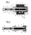
- the solenoid winding 23 is crossed by the cylindrical part 4 of the valve body and is fixed to said valve body by pressing the tightening face 31 of the nut 28 on the one (26) of its transverse faces with the interposition of a seal 34, and, by pressing its other transverse face 25 on the shoulder 8 with the interposition of a seal 35.
- the length of the solenoid winding 23 (distance between the faces 25 and 26) is such that, after tightening the nut 28, the lug 32 remains unsupported by the end 21A of the core 21, the elastic return member 19 being alone to act on the shutter member 14 and keeping it in its first shutter position of the conduit 15A-15B.
- the seal 33 is interposed between the bottom 39 of the cylinder and the shoulder 12 of the valve body.
- the safety valve is provided with its electromagnet, including the solenoid winding 23, capable of controlling the opening thereof, and therefore the communication of the parts 15A, 15B of its internal duct, by supplying electrical energy to the solenoid winding 23.
- the working chamber 40 can be placed in communication with the duct 43 and be either supplied with pressurized fluid, or be placed in communication with a reservoir fluid discharge.
- the cessation of the supply of electrical energy to the solenoid winding 23 removes the force which it developed and which was antagonistic and preponderant compared to the restoring force of the elastic member 19: the elastic member 19 acts alone and places the shutter member 14 in its first sealed shutter position of the internal conduit 15A-15B.
- the user has the possibility of modifying the configuration of the safety valve, shown in FIG. 1, to adopt the configuration of FIG. 2.
- the user has the possibility of modifying the configuration of the safety valve, shown in FIG. 1, to adopt the configuration of FIG. 2.
- the user has the possibility of modifying the configuration of the safety valve, shown in FIG. 1, to adopt the configuration of FIG. 2.
- the communication between the parts 15A and 15B of the internal conduit of the safety valve which again makes possible the communication of the working chamber 40 of the jack 36 with the external conduit 43 and performs the unlocking of the member controlled by this jack: unlocking of a tail lift in the handling position of a load, or the like, for example.
- the safety valve on the one hand, is mounted with a seal (seal 33) on the jack 36, on the other hand, is itself mounted in a seal (seals 34.35 ).
- No humidity is likely to attack by corrosion the internal mechanism of the safety valve, which eliminates any risk of deterioration thereby, and reduces the risk of breakdowns, this permanently, whereas, according to certain previous provisions, moisture could penetrate permanently inside the mechanism by the non-tight clearance which existed between the thread of the release screw of the shutter member and the corresponding thread of the valve body.
Landscapes
- Engineering & Computer Science (AREA)
- General Engineering & Computer Science (AREA)
- Mechanical Engineering (AREA)
- Physics & Mathematics (AREA)
- Electromagnetism (AREA)
- Magnetically Actuated Valves (AREA)
- Safety Valves (AREA)
Applications Claiming Priority (2)
| Application Number | Priority Date | Filing Date | Title |
|---|---|---|---|
| FR9012203 | 1990-10-03 | ||
| FR9012203A FR2667674B1 (fr) | 1990-10-03 | 1990-10-03 | Clapet de securite pour circuit de fluide. |
Publications (1)
| Publication Number | Publication Date |
|---|---|
| EP0479650A1 true EP0479650A1 (fr) | 1992-04-08 |
Family
ID=9400908
Family Applications (1)
| Application Number | Title | Priority Date | Filing Date |
|---|---|---|---|
| EP91402572A Withdrawn EP0479650A1 (fr) | 1990-10-03 | 1991-09-26 | Clapet de sécurité pour circuit de fluide |
Country Status (4)
| Country | Link |
|---|---|
| US (1) | US5113896A (ja) |
| EP (1) | EP0479650A1 (ja) |
| JP (1) | JPH05141553A (ja) |
| FR (1) | FR2667674B1 (ja) |
Cited By (2)
| Publication number | Priority date | Publication date | Assignee | Title |
|---|---|---|---|---|
| GB2298610A (en) * | 1995-03-06 | 1996-09-11 | Happich Gmbh Gebr | Gas injector for the moulding of plastic hollow parts |
| WO1996037720A1 (de) * | 1995-05-26 | 1996-11-28 | Hartmann + Lämmle Gmbh & Co. Kg | Drei-stellungs-magnetventil |
Families Citing this family (7)
| Publication number | Priority date | Publication date | Assignee | Title |
|---|---|---|---|---|
| US5339777A (en) * | 1993-08-16 | 1994-08-23 | Caterpillar Inc. | Electrohydraulic device for actuating a control element |
| JP3719566B2 (ja) * | 1996-05-27 | 2005-11-24 | 株式会社デンソー | 電磁弁 |
| IT246635Y1 (it) * | 1999-04-09 | 2002-04-09 | Claber Spa | Solenoide di comando per elettrovalvola in particolare per il controllo di impianti di irrigazione |
| US6999941B1 (en) * | 2000-07-11 | 2006-02-14 | Amazon.Com, Inc. | Providing gift clustering functionality to assist a user in ordering multiple items for a recipient |
| AU2003267396A1 (en) * | 2002-09-25 | 2004-04-23 | Bsh Bosch Und Siemens Hausgerate Gmbh | Gas tap comprising an electromagnetic safety valve and magnetic insert for an electromagnetic safety valve |
| DE102010002733B4 (de) * | 2010-03-10 | 2024-02-15 | Deere & Company | Druckbegrenzungsventil für eine Rundballenpresse |
| DE102019113409A1 (de) * | 2019-05-21 | 2020-11-26 | ECO Holding 1 GmbH | Aktuator und Ventilblock |
Citations (2)
| Publication number | Priority date | Publication date | Assignee | Title |
|---|---|---|---|---|
| GB853469A (en) * | 1955-12-21 | 1960-11-09 | Baird & Tatlock Ltd | Improvements in or relating to valves for controlling fluid flow |
| FR1257143A (fr) * | 1960-02-17 | 1961-03-31 | Regulation Automatique | Vanne électromagnétique |
Family Cites Families (2)
| Publication number | Priority date | Publication date | Assignee | Title |
|---|---|---|---|---|
| US4790345A (en) * | 1987-03-17 | 1988-12-13 | Parker-Hannifin Corporation | Proportional valve |
| JPH0277376U (ja) * | 1988-12-01 | 1990-06-13 |
-
1990
- 1990-10-03 FR FR9012203A patent/FR2667674B1/fr not_active Expired - Fee Related
-
1991
- 1991-09-26 EP EP91402572A patent/EP0479650A1/fr not_active Withdrawn
- 1991-09-30 US US07/767,517 patent/US5113896A/en not_active Expired - Fee Related
- 1991-10-03 JP JP3256609A patent/JPH05141553A/ja active Pending
Patent Citations (2)
| Publication number | Priority date | Publication date | Assignee | Title |
|---|---|---|---|---|
| GB853469A (en) * | 1955-12-21 | 1960-11-09 | Baird & Tatlock Ltd | Improvements in or relating to valves for controlling fluid flow |
| FR1257143A (fr) * | 1960-02-17 | 1961-03-31 | Regulation Automatique | Vanne électromagnétique |
Cited By (4)
| Publication number | Priority date | Publication date | Assignee | Title |
|---|---|---|---|---|
| GB2298610A (en) * | 1995-03-06 | 1996-09-11 | Happich Gmbh Gebr | Gas injector for the moulding of plastic hollow parts |
| GB2298610B (en) * | 1995-03-06 | 1998-10-28 | Happich Gmbh Gebr | Gas injector for the moulding of hollow parts |
| ES2139482A1 (es) * | 1995-03-06 | 2000-02-01 | Happich Gmbh Gebr | Inyector de gas para el moldeo de piezas huecas de materia plastica. |
| WO1996037720A1 (de) * | 1995-05-26 | 1996-11-28 | Hartmann + Lämmle Gmbh & Co. Kg | Drei-stellungs-magnetventil |
Also Published As
| Publication number | Publication date |
|---|---|
| FR2667674A1 (fr) | 1992-04-10 |
| US5113896A (en) | 1992-05-19 |
| JPH05141553A (ja) | 1993-06-08 |
| FR2667674B1 (fr) | 1993-08-20 |
Similar Documents
| Publication | Publication Date | Title |
|---|---|---|
| FR2638731A1 (fr) | Procede pour assurer une deconnexion entre un bras de chargement de fluide et une citerne dont l'un est porte par un vehicule en cas de depart inopine du vehicule; bras de chargement de fluide mettant en oeuvre ce procede; deconnecteur de securite pour sa mise en oeuvre | |
| FR2644765A2 (fr) | Frein electromagnetique a machoires de serrage | |
| FR2546460A1 (fr) | Amplificateur hydraulique de force de freinage, notamment pour vehicule automobile | |
| FR2527152A1 (fr) | Maitre-cylindre pour freins hydrauliques de vehicules automobiles | |
| EP0479650A1 (fr) | Clapet de sécurité pour circuit de fluide | |
| FR2573711A1 (fr) | Systeme hydraulique de freinage avec regulation du glissement | |
| FR2656049A1 (fr) | Accumulateur de pression a piston, notamment pour systeme de freinage a regulation du glissement de traction. | |
| FR2460818A1 (fr) | Regulateur de pression jumele pour deux circuits de freinage | |
| FR2462573A1 (fr) | Injecteur a teton d'etranglement | |
| FR2460240A1 (fr) | Dispositif de commande de pression de freinage pour installations de freinage de vehicules automobiles | |
| FR2654801A2 (fr) | Reservoir de gaz sous pression avec controle du courant gazeux delivre. | |
| FR2499642A1 (fr) | Soupape de surete pour presse actionnable hydrauliquement | |
| EP0493155B1 (fr) | Soupape de purge pour circuit hydraulique et procédé de purge d'un circuit hydraulique muni d'une telle soupape | |
| FR2628369A1 (fr) | Dispositif de mise a l'air libre et de securite contre le remplissage excessif pour reservoir | |
| FR2509805A1 (fr) | Amplificateur de force hydraulique | |
| EP0146614B1 (fr) | Relai electro-fluidique | |
| EP0449678B1 (fr) | Compensateur de freinage asservi à la charge | |
| FR2629776A1 (fr) | Servofrein | |
| FR2560336A1 (fr) | Systeme de compensation de l'usure d'un joint d'etancheite | |
| FR2496578A1 (fr) | Regulateur de freinage pour installation de freinage hydraulique de vehicule automobile | |
| FR2584356A1 (fr) | Dispositif d'assistance hydraulique | |
| EP0247913B1 (en) | Hydraulic pressure booster | |
| FR2673337A3 (fr) | Moteur electrique avec un arbre d'induit qui a deux epaulements formant butee. | |
| BE554893A (ja) | ||
| FR2579156A1 (fr) | Soupape de frein |
Legal Events
| Date | Code | Title | Description |
|---|---|---|---|
| PUAI | Public reference made under article 153(3) epc to a published international application that has entered the european phase |
Free format text: ORIGINAL CODE: 0009012 |
|
| AK | Designated contracting states |
Kind code of ref document: A1 Designated state(s): AT CH DE ES GB IT LI NL SE |
|
| 17P | Request for examination filed |
Effective date: 19920808 |
|
| 17Q | First examination report despatched |
Effective date: 19930219 |
|
| STAA | Information on the status of an ep patent application or granted ep patent |
Free format text: STATUS: THE APPLICATION HAS BEEN WITHDRAWN |
|
| 18W | Application withdrawn |
Withdrawal date: 19930615 |