EP0478928B1 - Hammermutter - Google Patents
Hammermutter Download PDFInfo
- Publication number
- EP0478928B1 EP0478928B1 EP91113224A EP91113224A EP0478928B1 EP 0478928 B1 EP0478928 B1 EP 0478928B1 EP 91113224 A EP91113224 A EP 91113224A EP 91113224 A EP91113224 A EP 91113224A EP 0478928 B1 EP0478928 B1 EP 0478928B1
- Authority
- EP
- European Patent Office
- Prior art keywords
- nut
- thread
- screwthread
- flanks
- screwed
- Prior art date
- Legal status (The legal status is an assumption and is not a legal conclusion. Google has not performed a legal analysis and makes no representation as to the accuracy of the status listed.)
- Expired - Lifetime
Links
- 238000000034 method Methods 0.000 claims description 2
- 238000003780 insertion Methods 0.000 description 5
- 230000037431 insertion Effects 0.000 description 5
- 230000005764 inhibitory process Effects 0.000 description 4
- 238000004519 manufacturing process Methods 0.000 description 4
- 230000000694 effects Effects 0.000 description 2
- 230000005923 long-lasting effect Effects 0.000 description 1
- 230000036316 preload Effects 0.000 description 1
Images

Classifications
-
- F—MECHANICAL ENGINEERING; LIGHTING; HEATING; WEAPONS; BLASTING
- F16—ENGINEERING ELEMENTS AND UNITS; GENERAL MEASURES FOR PRODUCING AND MAINTAINING EFFECTIVE FUNCTIONING OF MACHINES OR INSTALLATIONS; THERMAL INSULATION IN GENERAL
- F16B—DEVICES FOR FASTENING OR SECURING CONSTRUCTIONAL ELEMENTS OR MACHINE PARTS TOGETHER, e.g. NAILS, BOLTS, CIRCLIPS, CLAMPS, CLIPS OR WEDGES; JOINTS OR JOINTING
- F16B39/00—Locking of screws, bolts or nuts
- F16B39/22—Locking of screws, bolts or nuts in which the locking takes place during screwing down or tightening
- F16B39/28—Locking of screws, bolts or nuts in which the locking takes place during screwing down or tightening by special members on, or shape of, the nut or bolt
- F16B39/30—Locking exclusively by special shape of the screw-thread
-
- F—MECHANICAL ENGINEERING; LIGHTING; HEATING; WEAPONS; BLASTING
- F16—ENGINEERING ELEMENTS AND UNITS; GENERAL MEASURES FOR PRODUCING AND MAINTAINING EFFECTIVE FUNCTIONING OF MACHINES OR INSTALLATIONS; THERMAL INSULATION IN GENERAL
- F16B—DEVICES FOR FASTENING OR SECURING CONSTRUCTIONAL ELEMENTS OR MACHINE PARTS TOGETHER, e.g. NAILS, BOLTS, CIRCLIPS, CLAMPS, CLIPS OR WEDGES; JOINTS OR JOINTING
- F16B37/00—Nuts or like thread-engaging members
- F16B37/04—Devices for fastening nuts to surfaces, e.g. sheets, plates
- F16B37/041—Releasable devices
- F16B37/042—Releasable devices locking by rotation
Definitions
- the invention relates to a nut with an escapement for screwing in a threaded bolt.
- hammer nuts have roughly the outer shape of a hammer head, i.e. their extension in the plane perpendicular to the thread axis is significantly smaller in one axis than in the axis perpendicular to it.
- This means that these hammer nuts can easily be inserted into the insertion slot of undercut grooved components, such as rails, and then rotated 90 ° to the stop (nut-specific design), whereby they can no longer be pulled out of the groove, because in this position the nut width is larger than the width of the insertion slot.
- a threaded bolt is screwed into the hammer nut and is connected to a second component outside of the insertion slot mentioned. Due to the screwing process, the hammer nut is pressed against the undercut of the groove, resulting in a firm connection between the two components.
- a self-locking thread form is known from EP-0063677, in which the thread tips of the bolt are deformed when the nut is screwed on.
- the nut thread has two different flank angles, which makes the production complex.
- the object of the present invention is therefore to design a nut with a precisely defined escapement such that the strength of the escapement remains essentially the same over several screwing operations and that the nut can nevertheless be produced at a reasonable cost.
- the invention also provides a manufacturing process.
- FIG. 1 shows, as mentioned, a known hammer nut in side view and in plan view.
- the extension of the nut in one direction is denoted by a, where a is smaller than the width of the insertion slot of the undercut groove into which the nut 10 is inserted should, the extension in the other, perpendicular direction is denoted by b, where b is substantially larger than the width of the insertion slot, so that the surfaces 10b of the nut 10 represent stop surfaces for contact with the undercut of the groove mentioned.
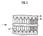
- ribs 30 protrude from the thread flanks of the last two thread turns, as can be clearly seen from the drawing. These ribs act in such a way that when the threaded bolt is screwed in, when the last two threads are reached, there is an inhibition, i.e. the nut is turned 90 ° before a preload is introduced into the connection and is thus placed in the correct position.
- the threaded bolt can be tightened, and the threaded bolt can then only be screwed back by means of a force that overcomes the inhibition.
- unwanted loosening of the screw connection is excluded, even with strong vibrations.
- the ribs protrude about 0.05 mm beyond the thread flanks, based on a standard nut M6. With these numerical values, the level of inhibition is approximately 1 to 2 Nm.
- the production of the ribs 30 in the nut thread takes place in such a way that grooves are cut or milled into the screw tap which cuts the nut thread, namely in the two thread turns adjacent to the drill tip.
- the depth of the grooves depends on the desired height of the ribs in the nut thread.
- the tap 21 must be screwed out of the nut in the opposite direction after the thread has been cut, because otherwise the subsequent, non-grooved threads of the drill 21 would cut away the resulting ribs or the tap 21 sticks in the nut 10.
Landscapes
- Engineering & Computer Science (AREA)
- General Engineering & Computer Science (AREA)
- Mechanical Engineering (AREA)
- Hand Tools For Fitting Together And Separating, Or Other Hand Tools (AREA)
- Details Of Spanners, Wrenches, And Screw Drivers And Accessories (AREA)
- Forging (AREA)
Description
- Die Erfindung betrifft eine Mutter mit Hemmung zum Einschrauben eines Gewindebolzens.
- In neuerer Zeit sind Verbindungssysteme auf den Markt gekommen, bei denen sogenannte Hammermuttern Verwendung finden. Diese Hammermuttern haben in etwa die äußere Gestalt eines Hammerkopfs, d.h., ihre Erstreckung in der zur Gewindeachse senkrechten Ebene ist in einer Achse wesentlich geringer als in der dazu senkrechten Achse. Damit können diese Hammermuttern in den Einführschlitz von hinterschnittene Nuten aufweisenden Bauelementen, beispielsweise Schienen, mühelos eingeführt und dann um 90° bis Anschlag (mutternspezifische Konstruktion) gedreht werden, wobei sie dann nicht mehr aus der Nut herausgezogen werden können, weil in dieser Position die Mutterbreite größer ist als die Breite des Einführschlitzes. In die Hammermutter wird ein Gewindebolzen eingeschraubt, der außerhalb des erwähnten Einführschlitzes mit einem zweiten Bauelement verbunden ist. Durch den Schraubvorgang wird die Hammermutter gegen die Hinterschneidung der Nut gepreßt, womit sich eine feste Verbindung zwischen den beiden Bauelementen ergibt.
- Wünnschenswert ist es nun, Hammermuttern, wie auch andere übliche Muttern, mit einer Hemmung zu versehen, damit die Mutter beim Einschrauben der Schraube um 90° bis Anschlag gedreht wird und langerichtig, wie vorbeschrieben, beim Kraftangriff in der Schiene liegt. Beim Ausschrauben dreht die Hemmung des Gewindes die Mutter exakt wieder um 90° zurück, so daß die Demontage einfachst erfolgen kann. Des weiteren bewirkt die Hemmung, daß die Verbindung bei starken Vibrationen eine Lockerung verhindert.
- Aus der EP-0063677 ist eine selbsthemmende Gewindeform bekannt, bei der die Gewindespitzen des Bolzens beim Aufschrauben der Mutter verformt werden. Das Muttergewinde weist dabei zwei unterschiedliche Flankenwinkel auf, was die Herstellung aufwendig macht.
- Bei der EP-0441224 sind im Muttergewinde Vertiefungen ausgebildet, wobei eine Klemmwirkung durch unterschiedliche Steilheit der Gewindeflanken erzielt wird. Auch diese Gewindeform ist kompliziert in der Herstellung, da sich die Flankenform im Querschnitt über der Gewindelänge ändert.
- Aufgabe der vorliegenden Erfindung ist es deshalb, eine Mutter mit exakt definierter Hemmung so auszubilden, daß die Stärke der Hemmung über mehrere Schraubvorgänge im wesentlichen gleich bleibt und daß die Mutter trotzdem mit vertretbaren Kosten herstellbar ist.
- Diese Aufgabe wird durch Anspruch 1 gelöst.
- Die Erfindung gibt auch ein Herstellungsverfahren an.
- Nachfolgend wird die Erfindung an einem Ausführungsbeispiel anhand der Zeichnungen näher erläutert. Es zeigen:
- Fig. 1
- eine übliche Hammermutter in Seiten- und Draufsicht, und
- Fig. 2
- eine Skizze zur Erläuterung einer bevorzugten Ausführungsform der Erfindung.
- Fig. 1 zeigt, wie erwähnt, eine bekannte Hammermutter in Seitenansicht und in Draufsicht. In der axialen Durchbohrung dieser im ganzen mit 10 bezeichneten Mutter befindet sich ein Innengewinde 11. Die Erstreckung der Mutter in der einen Richtung ist mit a bezeichnet, wobei a kleiner ist als die Breite des Einführschlitzes der hinterschnittenen Nut, in welche die Mutter 10 eingesetzt werden soll, die Erstreckung in der anderen, dazu senkrechten Richtung ist mit b bezeichnet, wobei b wesentlich größer ist als die Breite des Einführschlitzes, so daß die Flächen 10b der Mutter 10 Anschlagflächen zur Anlage an der Hinterschneidung der erwähnten Nut darstellen.
- Bei der bevorzugten Ausführungsform der Erfindung nach Fig. 2 stehen von den Gewindeflanken der letzten beiden Gewindegänge Rippen 30 ab, wie dies aus der Zeichnung klar ersichtlich ist. Diese Rippen wirken so, daß beim Einschrauben des Gewindebolzens bei Erreichen der letzten beiden Gewindegänge eine Hemmung auftritt, d.h., die Mutter wird um 90° gedreht, ehe eine Vorspannung in die Verbindung eingebracht wird und ist somit lagerichtig plaziert. Der Gewindebolzen kann festgezogen werden, wobei das Zurückschrauben des Gewindebolzens dann nur mittels einer die Hemmung überwindenden Kraft durchgeführt werden kann. Des weiteren ist ungewolltes Lockern der Schraubverbindung ausgeschlossen, auch bei stärkeren Vibrationen.
- Um hier einen Anhaltspunkt zu geben, sei angegeben, daß die Rippen etwa 0,05 mm über die Gewindeflanken hinauszuragen, bezogen auf eine Normmutter M6. Mit diesen Zahlenwerten beträgt die Stärke der Hemmung etwa 1 bis 2 Nm.
- Die Herstellung der Rippen 30 im Muttergewinde erfolgt in der Weise, daß in den das Muttergewinde schneidenden Gewindebohrer 21 Nuten eingeschnitten bzw. eingefräst werden, und zwar in die beiden der Bohrerspitze benachbarten Gewindegänge. Die Tiefe der Nuten richtet sich nach der gewünschten Höhe der Rippen im Muttergewinde. Der Gewindebohrer 21 ist nach dem Einschneiden des Gewindes in Gegenrichtung wieder aus der Mutter herauszuschrauben, weil ansonsten die nachfolgenden, keine Nuten aufweisenden Gewindegänge des Bohrers 21 die entstandenen Rippen wegschneiden würden bzw. der Gewindebohrer 21 in der Mutter 10 festfährt.
- Die beschriebenen Ausführungsformen können Abwandlungen erfahren, ohne den Bereich der Erfindung zu verlassen. Dies betrifft insbesondere die Zahlenangaben für die Höhe und Breite der Rippen und die Anzahl der die Vorsprünge aufweisenden Gewindegänge.
Claims (4)
- Mutter mit Hemmung zum Einschrauben eines Gewindebolzens, dadurch gekennzeichnet, daß die in Einschraubrichtung des Gewindebolzens letzten Gewindegänge des Muttergewindes mit von ihren Gewindeflanken abstehenden, rippenartigen Vorsprüngen (30) gefertigt sind.
- Mutter nach Anspruch 1, dadurch gekennzeichnet, daß die rippenartigen Vorsprünge bezogen auf eine Normmutter M6 um etwa 0,05 mm über die Gewindeflanken hinausragen.
- Mutter nach Anspruch 1 oder 2, dadurch gekennzeichnet, daß die Anzahl der die Vorsprünge aufweisenden Gewindegänge zwei oder drei beträgt.
- Verfahren zum Herstellen einer Mutter nach einem der Ansprüche 1 bis 3, dadurch gekennzeichnet, daß in die Gewindeflanken der vordersten Gewindegänge des zum Einschneiden des Muttergewindes verwendeten Gewindebohrers Nuten eingefräst oder eingeschnitten werden und daß der Gewindebohrer beim Einschneiden des Gewindes in die Mutter zunächst in der einen Drehrichtung in die Mutter hineingeschraubt und anschließend mit entgegengesetzter Drehrichtung aus dieser wieder herausgeschraubt wird.
Applications Claiming Priority (2)
| Application Number | Priority Date | Filing Date | Title |
|---|---|---|---|
| DE4031602 | 1990-10-05 | ||
| DE4031602A DE4031602A1 (de) | 1990-10-05 | 1990-10-05 | Hammermutter |
Publications (3)
| Publication Number | Publication Date |
|---|---|
| EP0478928A2 EP0478928A2 (de) | 1992-04-08 |
| EP0478928A3 EP0478928A3 (en) | 1992-09-02 |
| EP0478928B1 true EP0478928B1 (de) | 1994-11-09 |
Family
ID=6415690
Family Applications (1)
| Application Number | Title | Priority Date | Filing Date |
|---|---|---|---|
| EP91113224A Expired - Lifetime EP0478928B1 (de) | 1990-10-05 | 1991-08-06 | Hammermutter |
Country Status (3)
| Country | Link |
|---|---|
| EP (1) | EP0478928B1 (de) |
| DE (2) | DE4031602A1 (de) |
| ES (1) | ES2063418T3 (de) |
Families Citing this family (11)
| Publication number | Priority date | Publication date | Assignee | Title |
|---|---|---|---|---|
| DE19928144A1 (de) * | 1999-06-19 | 2000-12-21 | Altratec Montagesysteme | Vorrichtung zur Verbindung eines Körpers |
| SE516342C2 (sv) | 2000-04-27 | 2001-12-17 | Jokab Safety Ab | Insticksmutter till ett skruv-mutter-förband |
| US6983667B2 (en) * | 2001-07-23 | 2006-01-10 | University Of Arizona | Impact micro-positioning actuator |
| DE202004017021U1 (de) * | 2004-11-02 | 2006-03-16 | Rehau Ag + Co. | Vorrichtung zur Verbindung eines Montageprofils mit einem weiteren Montagebauteil sowie Baugruppe mit einer derartigen Vorrichtung |
| DE102006048053A1 (de) * | 2006-10-11 | 2008-04-17 | Bayerische Motoren Werke Ag | Schraube zum schwingungsentkoppelten Verbinden von Bauteilen und eine Verbindungsanordnung unter Verwendung dieser Schraube |
| EP2607586B1 (de) * | 2007-09-05 | 2014-09-03 | Dr. Hahn GmbH & Co. KG | Baugruppe und Befestigungsvorrichtung |
| DE202010015819U1 (de) * | 2010-11-29 | 2011-01-20 | Acument Gmbh & Co. Ohg | Selbstsichernde Mutter |
| US9921029B2 (en) | 2014-01-10 | 2018-03-20 | Magpul Industries Corp. | Connector |
| US9239210B2 (en) | 2014-04-03 | 2016-01-19 | Magpul Industries Corp. | Firearm accessory mounting interface |
| DE102016111286A1 (de) * | 2016-06-20 | 2017-12-21 | Bossard Ag | Gewindeträger |
| DE102018119442A1 (de) * | 2018-08-09 | 2020-02-13 | Sortimo International Gmbh | Hammermutter und Profilelement für eine Hammermutter |
Family Cites Families (8)
| Publication number | Priority date | Publication date | Assignee | Title |
|---|---|---|---|---|
| DE2247289A1 (de) * | 1972-09-27 | 1974-03-28 | Siemens Ag | Unmittelbare oder mittelbare schraubverbindung mit einem kunststoffteil |
| DE2527557A1 (de) * | 1975-06-20 | 1977-01-13 | Glynwid Screws & Fastenings Lt | Reibschlusschraube |
| USRE31284E (en) * | 1978-02-10 | 1983-06-21 | Locking fastener | |
| US4150702A (en) * | 1978-02-10 | 1979-04-24 | Holmes Horace D | Locking fastener |
| FR2485121A1 (fr) * | 1980-06-20 | 1981-12-24 | Sofrariv Frappe Rivets | Vis indesserrable et son procede de fabrication |
| US4826377A (en) * | 1981-04-27 | 1989-05-02 | Holmes Horace D | Self-locking fastener and tool for making same |
| DE3601389A1 (de) * | 1986-01-18 | 1987-07-23 | Kellermann Fa Rudolf | Verbindungselement nach art einer schrauben/muttern-verbindung |
| DE4003892A1 (de) * | 1990-02-09 | 1991-08-14 | Haerle Anton | Selbsthemmendes gewinde |
-
1990
- 1990-10-05 DE DE4031602A patent/DE4031602A1/de not_active Withdrawn
-
1991
- 1991-08-06 ES ES91113224T patent/ES2063418T3/es not_active Expired - Lifetime
- 1991-08-06 EP EP91113224A patent/EP0478928B1/de not_active Expired - Lifetime
- 1991-08-06 DE DE59103489T patent/DE59103489D1/de not_active Expired - Fee Related
Also Published As
| Publication number | Publication date |
|---|---|
| ES2063418T3 (es) | 1995-01-01 |
| DE59103489D1 (de) | 1994-12-15 |
| EP0478928A2 (de) | 1992-04-08 |
| DE4031602A1 (de) | 1992-04-09 |
| EP0478928A3 (en) | 1992-09-02 |
Similar Documents
| Publication | Publication Date | Title |
|---|---|---|
| DE1914477C3 (de) | Schraubensicherung | |
| EP0478928B1 (de) | Hammermutter | |
| DE3032167C2 (de) | Gegen unbeabsichtigtes Lösen gesicherte Muttern-Bolzen-Verbindung | |
| EP3405686A1 (de) | Kunststoff-gewindeelement sowie verbindungsanordnung bestehend aus einem kunststoffträgerteil und einem kunststoff-gewindeelement | |
| DE3743010C2 (de) | ||
| DE3032166C2 (de) | Gegen unbeabsichtigtes Lösen gesicherte Bolzen-Muttern-Verbindung | |
| EP0109528B1 (de) | Selbstschneidender Gewindeeinsatz | |
| DE3939092C2 (de) | Verschlußkörper für Gewindebohrungen | |
| DE3000249A1 (de) | Schneidschraube | |
| WO2018172356A1 (de) | Elektronikgehäuse und verfahren zur einhausung von elektronikkomponenten | |
| WO2017102376A1 (de) | Gewindeelement | |
| DE19753755C2 (de) | Schlupfarme Schraubverbindung für Stäbe im Bauwesen mit geometrisch definierter Konterung | |
| DE2620996A1 (de) | Verriegelungsmutter | |
| DE9016087U1 (de) | Schraube | |
| DE8202339U1 (de) | Schraube | |
| DE4316808C2 (de) | Spannstück für Rohrelemente | |
| EP0377201B1 (de) | Selbstsichernde Schraubverbindung | |
| DE3311378C1 (de) | Selbstschneidender Gewindeeinsatz | |
| DE102020102294A1 (de) | Montagesystem | |
| DE4039402A1 (de) | Schraube mit selbstsicherndem gewinde | |
| DE102024110187A1 (de) | Verbindungselement mit Räumabschnitt, Rohteil zur Herstellung dieses Verbindungselements und Schraubverbindung mit diesem Verbindungselement | |
| DE864335C (de) | Schraubensicherung, insbesondere Sicherungsmutter | |
| DE1958573A1 (de) | Vorrichtung zum Einspannen von Wendeschneidplatten | |
| EP0378790B1 (de) | Bauelement als Teil einer Schraubverbindung | |
| DE1400909A1 (de) | Gewindeeinsatz |
Legal Events
| Date | Code | Title | Description |
|---|---|---|---|
| PUAI | Public reference made under article 153(3) epc to a published international application that has entered the european phase |
Free format text: ORIGINAL CODE: 0009012 |
|
| 17P | Request for examination filed |
Effective date: 19910816 |
|
| AK | Designated contracting states |
Kind code of ref document: A2 Designated state(s): CH DE ES FR GB IT LI SE |
|
| PUAL | Search report despatched |
Free format text: ORIGINAL CODE: 0009013 |
|
| AK | Designated contracting states |
Kind code of ref document: A3 Designated state(s): CH DE ES FR GB IT LI SE |
|
| 17Q | First examination report despatched |
Effective date: 19930811 |
|
| GRAA | (expected) grant |
Free format text: ORIGINAL CODE: 0009210 |
|
| AK | Designated contracting states |
Kind code of ref document: B1 Designated state(s): CH DE ES FR GB IT LI SE |
|
| ITF | It: translation for a ep patent filed | ||
| GBT | Gb: translation of ep patent filed (gb section 77(6)(a)/1977) |
Effective date: 19941104 |
|
| REF | Corresponds to: |
Ref document number: 59103489 Country of ref document: DE Date of ref document: 19941215 |
|
| REG | Reference to a national code |
Ref country code: ES Ref legal event code: FG2A Ref document number: 2063418 Country of ref document: ES Kind code of ref document: T3 |
|
| ET | Fr: translation filed | ||
| EAL | Se: european patent in force in sweden |
Ref document number: 91113224.9 |
|
| PLBE | No opposition filed within time limit |
Free format text: ORIGINAL CODE: 0009261 |
|
| STAA | Information on the status of an ep patent application or granted ep patent |
Free format text: STATUS: NO OPPOSITION FILED WITHIN TIME LIMIT |
|
| 26N | No opposition filed | ||
| REG | Reference to a national code |
Ref country code: GB Ref legal event code: IF02 |
|
| PGFP | Annual fee paid to national office [announced via postgrant information from national office to epo] |
Ref country code: DE Payment date: 20080818 Year of fee payment: 18 Ref country code: ES Payment date: 20080922 Year of fee payment: 18 Ref country code: CH Payment date: 20080912 Year of fee payment: 18 |
|
| PGFP | Annual fee paid to national office [announced via postgrant information from national office to epo] |
Ref country code: IT Payment date: 20080827 Year of fee payment: 18 Ref country code: FR Payment date: 20080818 Year of fee payment: 18 |
|
| PGFP | Annual fee paid to national office [announced via postgrant information from national office to epo] |
Ref country code: GB Payment date: 20080813 Year of fee payment: 18 |
|
| PGFP | Annual fee paid to national office [announced via postgrant information from national office to epo] |
Ref country code: SE Payment date: 20080807 Year of fee payment: 18 |
|
| REG | Reference to a national code |
Ref country code: CH Ref legal event code: PL |
|
| GBPC | Gb: european patent ceased through non-payment of renewal fee |
Effective date: 20090806 |
|
| PG25 | Lapsed in a contracting state [announced via postgrant information from national office to epo] |
Ref country code: LI Free format text: LAPSE BECAUSE OF NON-PAYMENT OF DUE FEES Effective date: 20090831 Ref country code: CH Free format text: LAPSE BECAUSE OF NON-PAYMENT OF DUE FEES Effective date: 20090831 |
|
| REG | Reference to a national code |
Ref country code: FR Ref legal event code: ST Effective date: 20100430 |
|
| PG25 | Lapsed in a contracting state [announced via postgrant information from national office to epo] |
Ref country code: DE Free format text: LAPSE BECAUSE OF NON-PAYMENT OF DUE FEES Effective date: 20100302 Ref country code: FR Free format text: LAPSE BECAUSE OF NON-PAYMENT OF DUE FEES Effective date: 20090831 |
|
| REG | Reference to a national code |
Ref country code: ES Ref legal event code: FD2A Effective date: 20090807 |
|
| PG25 | Lapsed in a contracting state [announced via postgrant information from national office to epo] |
Ref country code: GB Free format text: LAPSE BECAUSE OF NON-PAYMENT OF DUE FEES Effective date: 20090806 |
|
| PG25 | Lapsed in a contracting state [announced via postgrant information from national office to epo] |
Ref country code: IT Free format text: LAPSE BECAUSE OF NON-PAYMENT OF DUE FEES Effective date: 20090806 |
|
| PG25 | Lapsed in a contracting state [announced via postgrant information from national office to epo] |
Ref country code: SE Free format text: LAPSE BECAUSE OF NON-PAYMENT OF DUE FEES Effective date: 20090807 |
|
| PG25 | Lapsed in a contracting state [announced via postgrant information from national office to epo] |
Ref country code: ES Free format text: LAPSE BECAUSE OF NON-PAYMENT OF DUE FEES Effective date: 20090807 |