EP0478535A2 - Objet avec une couche en polymère, p.e. rouleau, coussin à pression, avec adhésion localisé et procédé pour sa fabrication - Google Patents
Objet avec une couche en polymère, p.e. rouleau, coussin à pression, avec adhésion localisé et procédé pour sa fabrication Download PDFInfo
- Publication number
- EP0478535A2 EP0478535A2 EP91890226A EP91890226A EP0478535A2 EP 0478535 A2 EP0478535 A2 EP 0478535A2 EP 91890226 A EP91890226 A EP 91890226A EP 91890226 A EP91890226 A EP 91890226A EP 0478535 A2 EP0478535 A2 EP 0478535A2
- Authority
- EP
- European Patent Office
- Prior art keywords
- roller
- coated
- cavity
- workpiece
- chamber
- Prior art date
- Legal status (The legal status is an assumption and is not a legal conclusion. Google has not performed a legal analysis and makes no representation as to the accuracy of the status listed.)
- Granted
Links
Images



Classifications
-
- D—TEXTILES; PAPER
- D21—PAPER-MAKING; PRODUCTION OF CELLULOSE
- D21F—PAPER-MAKING MACHINES; METHODS OF PRODUCING PAPER THEREON
- D21F3/00—Press section of machines for making continuous webs of paper
- D21F3/02—Wet presses
- D21F3/0209—Wet presses with extended press nip
- D21F3/0218—Shoe presses
- D21F3/0227—Belts or sleeves therefor
- D21F3/0236—Belts or sleeves therefor manufacturing methods
-
- B—PERFORMING OPERATIONS; TRANSPORTING
- B29—WORKING OF PLASTICS; WORKING OF SUBSTANCES IN A PLASTIC STATE IN GENERAL
- B29D—PRODUCING PARTICULAR ARTICLES FROM PLASTICS OR FROM SUBSTANCES IN A PLASTIC STATE
- B29D99/00—Subject matter not provided for in other groups of this subclass
- B29D99/0032—Producing rolling bodies, e.g. rollers, wheels, pulleys or pinions
-
- B—PERFORMING OPERATIONS; TRANSPORTING
- B30—PRESSES
- B30B—PRESSES IN GENERAL
- B30B15/00—Details of, or accessories for, presses; Auxiliary measures in connection with pressing
- B30B15/06—Platens or press rams
- B30B15/061—Cushion plates
-
- B—PERFORMING OPERATIONS; TRANSPORTING
- B30—PRESSES
- B30B—PRESSES IN GENERAL
- B30B3/00—Presses characterised by the use of rotary pressing members, e.g. rollers, rings, discs
- B30B3/005—Roll constructions
-
- D—TEXTILES; PAPER
- D21—PAPER-MAKING; PRODUCTION OF CELLULOSE
- D21F—PAPER-MAKING MACHINES; METHODS OF PRODUCING PAPER THEREON
- D21F1/00—Wet end of machines for making continuous webs of paper
- D21F1/36—Guiding mechanisms
- D21F1/40—Rolls
-
- D—TEXTILES; PAPER
- D21—PAPER-MAKING; PRODUCTION OF CELLULOSE
- D21F—PAPER-MAKING MACHINES; METHODS OF PRODUCING PAPER THEREON
- D21F3/00—Press section of machines for making continuous webs of paper
- D21F3/02—Wet presses
- D21F3/0209—Wet presses with extended press nip
- D21F3/0218—Shoe presses
-
- D—TEXTILES; PAPER
- D21—PAPER-MAKING; PRODUCTION OF CELLULOSE
- D21F—PAPER-MAKING MACHINES; METHODS OF PRODUCING PAPER THEREON
- D21F3/00—Press section of machines for making continuous webs of paper
- D21F3/02—Wet presses
- D21F3/0209—Wet presses with extended press nip
- D21F3/0218—Shoe presses
- D21F3/0227—Belts or sleeves therefor
-
- B—PERFORMING OPERATIONS; TRANSPORTING
- B29—WORKING OF PLASTICS; WORKING OF SUBSTANCES IN A PLASTIC STATE IN GENERAL
- B29L—INDEXING SCHEME ASSOCIATED WITH SUBCLASS B29C, RELATING TO PARTICULAR ARTICLES
- B29L2031/00—Other particular articles
- B29L2031/32—Wheels, pinions, pulleys, castors or rollers, Rims
Definitions
- the invention relates to a method for producing a workpiece coated with plastic, in particular with elastomer, on a curved and / or flat surface, for example a roller, pressure pad, pressure shoe, heating / cooling mat, lubricated bearing segment.
- the invention further relates to a workpiece produced by this method.
- rollers are often used not only to advance screen belts, but also to align or smooth the screen belts. For this reason, the lateral surfaces of these rollers are provided with corresponding profiles and coated with plastic which is evenly bonded to the coated and / or uncoated workpiece surface.
- the production of such coated rollers with profiles on the lateral surfaces is quite complex and requires costly production and additional auxiliary devices.
- applications of pressure pads, pressure shoes and pressure plates in pressure presses, die casting machines and refiners using hydraulic cylinders and guide mechanisms are known which counteract large reaction forces with short adjustment paths. The manufacture of these mechanisms is complex and costly.
- the invention is primarily characterized in that the plastic layer, in particular the elastomer layer, is produced locally without binding to the coated and / or uncoated workpiece surface and is conveniently lifted there from the coated and / or uncoated workpiece surface.
- the plastic coating has areas in which there is no or essentially no bond to the coated and / or uncoated workpiece surface, areas with different frictional resistance or different diameters, for example for a screen belt, are present on the lateral surface of the roller. It is precisely this different frictional resistance or different diameters on the lateral surface of the roller, which is optionally controlled in a targeted manner, that can be used for the alignment or smoothing of, for example, sieve belts.
- the resulting cavity will be of different sizes and this in turn will lead to a corresponding flow of medium or leads to different discharge quantities if the cavities are connected to the surface by small openings, this is advantageously used in the case of lubricated bearings or pressure shoes or coating and moistening rollers. Even with heating and cooling plates or rollers, the proximity of the medium to the surface and the controllability of the flow rate lead to applications in paper, plastic, pulp, printing and textile machine construction.
- corresponding pressure and reaction force can be exerted in at least one area of the interconnected cavities and, in the case of back pressure, through the body touching the surface, such as pressure plate, counter roller, screen cloth.
- the invention has set itself the task of cavity design, or profile design, or the varied heat transfer contact through the elevations on the coating surface easily and inexpensively by simply inserting strips or preformed inserts or a film or the like. or a coat of paint or the like. on the coated and / or uncoated workpiece surface easily repeatable and also possible in multiple layers.
- At least one tape or preformed insert or a film or the like or a paint or varnish layer or the like is expediently applied to the coated and / or uncoated workpiece surface, for example the outer surface of a roller, or a tape or preformed insert or film expediently partially, in particular glued to the edges, or the coated and / or uncoated workpiece surface smoothed locally to reduce the adhesion of the plastic layer, then at least the plastic, advantageously elastomer layer on the coated and / or uncoated workpiece surface, for example roller, Pressure pad, pressure shoe, heating / cooling mat, lubricated bearing segment, applied and is preferably gaseous medium, in particular air, and / or liquid medium between the coated and / or uncoated workpiece surface, for example jacket surface he a roller, and the at least one a tape or preformed insert or film or the like.
- one or the gaseous medium, in particular air, and / or liquid medium from an interior of the workpiece for example a roller, pressure pad, pressure shoe, heating / cooling mat, lubricated bearing segment, the unbounded contact surface of the at least one a tape or preformed insert or the like or the like. fed or passed on the coated and / or uncoated workpiece surface to the at least one band or preformed insert or the film or the like.
- This cavity is achieved, for example, by heating the belt or preformed insert or film or the like. or between the paint or varnish layer by microwave, and / or by resistance heating by means of electrical conduction and / or by chemical flushing or electrolytic dissolution, in order to separate the plastic layer from the coated and / or uncoated workpiece surface, for example the outer surface of a roller, pressure pad, Pressure shoe, heating / cooling mat, lubricated bearing segment, a reduction in adhesion or decrease in volume is achieved and the plastic, in particular the elastomer from the preformed insert or film or the like. or is lifted off between the paint or varnish layer.
- the dimensions of the at least one cavity or the chamber are expediently determined essentially by the dimensions of the paint, the lacquer layer or the tape or preformed insert or the film used or the like. certainly.
- the or each band is bent in the edge area in order to achieve better adhesion properties, if appropriate using suitable auxiliaries.
- the at least one band or preformed insert or the film or the like applied to the coated and / or uncoated workpiece surface, for example to the outer surface of a roller is expedient. bent in the edge area, whereby the at least one tape or preformed insert or film or the like.
- the at least one plastic, advantageously elastomer layer does not rest in the edge area on the workpiece surface to be coated, so that when the at least one plastic, advantageously elastomer layer is subsequently applied to the coated and / or uncoated workpiece surface, for example the outer surface of a roller, the at least one plastic, advantageously elastomer coating also largely, expediently completely between Edge region of the at least one band or preformed insert or the film or the like. and the coated and / or uncoated workpiece surface, for example the outer surface of a roller, is applied.
- the coated and / or uncoated workpiece surface for example the outer surface of a roller
- on the workpiece surface to be coated for example the outer surface of a roller, at least one piece of wire, a strip, a profile or the like.
- attached or arranged on the coated and / or uncoated workpiece surface, for example the outer surface of a roller at least one recess in order to produce a positive connection of the plastic, advantageously elastomer with the coated and / or uncoated workpiece surface, for example the outer surface of a roller.
- At least one tubular hollow body e.g. connected by a screw connection and / or chemically firmly to the coated and / or uncoated workpiece surface to be coated, for example the outer surface of a roller, so that when the at least one plastic, advantageously elastomer coating is subsequently applied to the coated and / or uncoated workpiece surface,
- the outer surface of a roller the at least one plastic, advantageously elastomer coating, as far as possible, expediently completely between the coated and / or uncoated workpiece surface, for example the outer surface of a roller, and the at least one tubular hollow body and on this.
- the formation of the film or of the insert part as a double-walled, bonded to the contours, for example glued, welded, adhesion promoter is advantageous, which is applied to the coated and / or uncoated workpiece surface before coating, for example glued, welded, and then by insertion gaseous medium, in particular air, and / or liquid medium, the cavities or chambers are enlarged in order to create a profile or a flow, for example for heat transfer, and / or by building up pressure to profile the workpiece surface.
- the individual layers are separated or fed together, so that a different profile formation is achieved.
- the individual layers are separated or fed together, so that a corresponding to the inflow according to the position and size of the opening and Feeding different discharge cross-sections are formed on the coating surface.
- the present invention also relates to a workpiece, for example a roller, coated with plastic, in particular with elastomer, on a curved and / or flat surface.
- a workpiece for example a roller, coated with plastic, in particular with elastomer, on a curved and / or flat surface.
- Such rollers are used for example in the paper industry. These rollers are mainly used to convey or dewater webs of fabric. Often, these rollers simultaneously align or smooth sieve belts, for example. For this purpose, such rollers have profiles. For better drainage in paper machines, there are numerous variants of manufacturing processes to achieve tangential circumferential grooves or elevations.
- Patents CH - A5 631504 KÜSTERS
- DE3612207 VALMET
- DE - C2 2725000 VALMET
- the invention has set itself the task of producing an adaptation of the roller to the sieve shape (similar to a walking tire) by elastic materials and changeable openings with compressible media or with draining liquids and thus longer contact time of the pressing and / or less rewetting by lifting the Avoid sieves when enlarging the cavities during drainage and thus make the drainage process better.
- coating is carried out by applying elastomer in the form of a groove.
- Profiling should be avoided as the grooving is only intended as a machining operation. Pressing the screen with a curved shoe according to DE-A1 3306838 (VOITH) compensates for the roll core deflection.
- rolls with profiles used in the paper industry are wire guide rolls, spreader rolls, wide nip rolls and dewatering rolls.
- the spreading is achieved by means of opposing helix which is raised in profile.
- DE-A1 2728219 an inlay grid provides a profiled surface as a coating.
- the nip roll according to patent DE-A1 3612207 achieves a uniform gap width of the press rolls of one of the deflections counteracting different support by pressure shoes between the roll shell and roll core.
- the invention has set itself the task of compensating for the different gap caused by the deflection in press rolls by adjusting the diameter of the coated roll and advantageously applying constant, or substantially constant pressure, by the cavities of the coating with uniform pressure and flow from the Inside the roller is reached.
- Screen guide rollers are used to align the screen belt in the axial direction transversely to the direction of rotation, a screen regulator being required to actuate the deflection.
- Spreader rollers usually have spiral elevations and serve to smooth or stretch the screen belt in the axial direction.
- Wide nip rollers have a soft elastomer coating and have the disadvantage that corresponding pressures cannot be applied.
- Additional elastomeric tape guides are used to prevent the elastic tape from being firmly attached to the body and thus to be able to carry out greater pressing effects without loss of adhesion of the coating.
- dewatering rollers also have elevations between which the liquid can flow off, so that rewetting e.g. a fabric web is avoided.
- the workpiece is primarily characterized in that on the coated and / or uncoated workpiece surface, for example the outer surface of a roller, there is at least one locally limited adhesion avoidant or inhibitor, the area of which has a feed or discharge for gaseous or liquid Medium especially air.
- the embodiment of the invention described above makes it possible to create areas with different frictional resistance on the lateral surface of a roller. In this way, with appropriate arrangement of these areas, an alignment or smoothing, for example of sieve belts, can take place.
- the at least one locally limited adhesion preventing agent or preventing agent or reducing agent is advantageous in the plastic, advantageously elastomer coating, and / or between the coated and / or uncoated workpiece surface, for example the outer surface of a roller, and the plastic Elastomer coating arranged cavity or chamber, which is advantageously connected to an inlet or outlet for gaseous or liquid medium.
- the workpiece expediently has a cavity or chamber system which consists of at least one which is arranged in the plastic, advantageously elastomer coating and / or between the coated and / or uncoated workpiece surface, for example the lateral surface of a roller, and the plastic, advantageously elastomer coating Cavity or chamber as well as a channel assigned to each cavity or chamber, through which the at least one cavity or chamber, optionally independently of one another, gaseous medium, in particular air, and / or liquid medium, in particular with variable pressure, can be supplied or is derivable.
- the at least one cavity or the chamber is made of a tape or preformed insert or a film or the like. formed, which is bent inward in the edge region and glued to the coated and / or uncoated workpiece surface.
- the at least one cavity or the chamber is advantageously arranged in a recess in the coated and / or uncoated workpiece surface and, if appropriate, a boundary surface of the at least one cavity or the chamber conforms to the coated and / or uncoated workpiece surface.
- the at least one cavity or the chamber is expediently divided into at least two cavity or chamber zones, and each cavity or chamber zone is gaseous medium, in particular air and / or liquid medium, in particular with, through an assigned channel, possibly independently of one another variable pressure, feedable or derivable.
- the at least one cavity or the chamber if appropriate each cavity or chamber zone, is expediently connected to an interior of the workpiece by an assigned channel, which is expediently arranged in the workpiece, by the assigned channel gaseous medium, in particular air, and or or liquid medium, in particular with variable pressure, from the interior of the at least one Cavity or chamber, optionally the cavity or chamber zones, for example independently of one another, can be fed or can be derived from the at least one cavity or the chamber, optionally of each cavity or chamber zone, for example independently of one another, into the interior.
- an assigned channel which is expediently arranged in the workpiece, by the assigned channel gaseous medium, in particular air, and or or liquid medium, in particular with variable pressure, from the interior of the at least one Cavity or chamber, optionally the cavity or chamber zones, for example independently of one another, can be fed or can be derived from the at least one cavity or the chamber, optionally of each cavity or chamber zone, for example independently of one another, into the interior.
- the at least one cavity or chamber is advantageously arranged in the axial direction, possibly advantageously parallel to one another, distributed over the coated and / or uncoated workpiece surface, for example the lateral surface of a roller.
- the at least one cavity or the chamber is arranged helically, in one, two or more passages, over the coated and / or uncoated workpiece surface, for example the lateral surface of a roller.
- profiling is used to smooth or stretch the screen belt in the axial direction.
- the at least one cavity or the chamber is advantageously arranged in any direction, in the case of a plurality of cavities or chambers advantageously distributed over the coated and / or uncoated workpiece surface, for example the outer surface of a roller.
- a plurality of cavities or chambers are arranged in a circular or rectangular shape around a common channel.
- the cavities or chambers are expediently of the same design, in particular of tubular design.
- At least one profile of variable size can be formed on the coated and / or uncoated workpiece surface, for example the outer surface of a roller, and by discharging gaseous medium, in particular air and / or liquid medium, from the at least one cavity or chamber, optionally from the cavity or chamber zones, for example independent of one another, expediently the at least one profile can be removed into the interior of the workpiece.
- the workpiece is expediently designed as a roller and, from the outside, on one, advantageously on both end faces in the axis of rotation of the roller, expediently via a rotating part arranged on the or each end face, gaseous medium, in particular air, and / or liquid medium, in particular with variable pressure through the interior of the roller and through a bore arranged in the axis of rotation of the roller and at least one pin, which is expediently arranged in the interior of the roller, vertical to the axis of rotation, of the at least one cavity or chamber, optionally assigned to each cavity or chamber zone, arranged in the roller, for example independently of one another, the at least one cavity or chamber, optionally the cavity - or chamber zones can be supplied or derived from the at least one cavity or the chamber, if appropriate independently from the outside of the cavity or chamber zones, for example independently of one another.
- the workpiece is designed as a roller, and the interior of the roller is divided into at least two interior spaces by at least one advantageous dividing wall arranged vertically to the axis of rotation of the roller, and from the outside on both end faces via one in each case in the axis of rotation Roller arranged rotating part gaseous medium, in particular air, and / or liquid medium, in particular with variable pressure by means of a bore arranged in the axis of rotation of the roller through the associated interior through the at least one cavity or the chamber, optionally through the cavity or chamber zones the assigned channel, e.g. can be supplied independently of one another or from the at least one cavity or the chamber, if appropriate from the cavity or chamber zones e.g. can be derived independently from each other.
- the assigned channel e.g. can be supplied independently of one another or from the at least one cavity or the chamber, if appropriate from the cavity or chamber zones e.g. can be derived independently from each other.
- the adhesion preventing agent or preventing agent or reducing agent is a coating or a local design, e.g. Smoothing on the coated and / or uncoated workpiece surface that has no or essentially no bond with the plastic, in particular elastomer coating.
- a profiling or shaping of the cavities or chambers is counteracted by attaching rigid bodies to the coating surface, such as a pressure stamp, molded body, support plate
- pressure is built up when gaseous medium, in particular air, or in the case of liquid medium, is supplied, which is expedient is transferred to construction elements, or is used to adjust the position of large loads, or to adjust the position under high reaction force.
- gaseous medium in particular air, or in the case of liquid medium
- the flat workpiece for example, as a pressure stamp, pressure plate or molded body, in the case of the curved workpiece as a press shoe, ramp wedge or nestling plate.
- the cavities are connected to the coating surface with tubular insert parts, or with double-walled foils, or by means of an adhesion reducer, so that the applied pressure of the gaseous or liquid medium in the cavity or chamber system leads to the escape of the medium on the workpiece surface.
- rollers in the paper industry, plastics industry Printing machines are areas of application for these workpieces.
- FIGS. 1, 2 and 6 show perspective views of the roller according to the invention
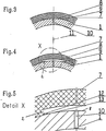
- FIGS. 3, 4, 5, 7 and 8 show a vertical section of a part of the roller in the region of the running surface
- FIG. 9a is a vertical section of one half of the roller 9b is a plan view of the coated, chambered outer surface of the other roller half
- FIG. 10a is a vertical section of a roller half according to the invention
- FIG. 10b is a plan view of the coated, chambered outer surface of the other roller half.
- 1 to 10, 1 denotes the roller body.
- FIGS. 10 to 13 show cross sections of flat coated workpieces
- FIG. 11 shows the use of the multi-layer chamber systems on a pressure pad.
- FIG. 12 shows the flat and / or curved workpiece as a coating, plate, or roller with a chamber system that extends to the surface.
- FIG. 13 shows a pressure plate with the hollow body in the form of a tubular chamber connected to the workpiece surface.
- a wire guide roller according to the invention is shown.
- the chamber 2 is shown in the state of being largely filled with the medium and is wrapped in a helical shape, in each case from the inside to the outside in the opposite direction, the roller body 1.
- the helix is made stronger or weaker, which is used for largely complete filling on both sides with medium, spreading effect and one-sided largely complete filling with medium.
- the screen is advanced in the direction of the larger roller diameter, so that controlled regulation is achieved by supplying or discharging medium, as a result of which the adjustment device previously required is no longer required.
- FIG. 2 shows chambers arranged in the axial direction on the lateral surface of the roller before the coating process. With 2 the chambers, with 3 the feeding of the roller with medium, with 4 the supply opening leading to the chamber 2.
- FIG. 3 shows a chamber which is arranged on the running surface of the roller after the elastomer coating and is only partially filled with medium.
- Numeral 10 denotes a channel arranged in the roller body 1
- 8 denotes a band or preformed insert which is applied to the roller body 1 and is bent in the edge region, 9 the edge region of the band, 7 the elastomer layer and 11 the interior of the roller .
- Medium becomes from the interior 11 of the roller through the channel 10 the band 8 bent over in the edge region 9 in order to fill the chamber 2 as completely as possible with medium, as shown in FIG. 4 below.
- FIG. 4 shows the film arranged on the outer surface of the roller coated with elastomer, which is lifted from the coated and / or uncoated workpiece surface by filling with medium and forms the chamber 2.
- the film bent over in the edge region 9 is designated by 8, and the elastomer layer applied to the coated and / or uncoated workpiece surface is designated by 7.
- the edge region 9 of the film 8 is bent over, so that the coating material 7 is infiltrated up to the point of contact of the adhesive tape 8 with the roller body 1. This increases the strength of the connection between roller body 1 and film, because the adhesive base formed from elastomer coating 7 and roller body 1 is not subjected to tensile stress.
- the internal pressure of the chamber 2 formed from the film 8 by filling the medium is transferred only to the elastomer coating.
- Fig. 5 is an enlarged view of the part "X" shown in Fig. 4 of the roller according to the invention.
- 10 denotes the channel arranged in the roller body 1, 2 the chamber arranged on the roller body 1, 12 the elastomer coating in the edge region 9 of the chamber 2 and 13 the elkastomer wedge of the coating arranged between the roller body 1 and chamber 2. From the illustration it can be seen that after application of the film 8 on the roller body 1, which is bent over in the edge region 9, a wedge-shaped infiltration of the film 8 takes place, in the area of the wedge 13 there are no longer any tensile forces, so that the adhesive base does not occur in this area is overused and dissolves. After the coating, a complete filling with medium is carried out as far as possible, the film 8 detaching from the roller body 1 due to the medium pressure applied and the flap of the adhesive tape being opened by the internal pressure.
- 6 to 8 show variants for improving the adhesion of the coating to the roller body 1.
- FIG. 6 denotes a tubular, flat-pressed molded body, 20 a feed opening, 16 a bar and 15 a screw.
- the tubular molded body 2 is glued to the roller body 1 prior to coating with elastomer, whereby a mechanical adhesion improvement is achieved by strips 16 arranged near the molded body 2, which are welded to the roller body 1 or screwed on by means of screws 15.
- 14 denotes a wire welded onto the roller body 1, 16 a bar and 15 a screw.
- the welded-on wire 14 improves the mechanical adhesion of the elastomer coating 7 on the roller body 1.
- FIG. 8 shows the media guidance or discharge to or from the tubular molded body 2 through a channel 10 arranged in the roller body 1, which has a screw connection 22 accessible from the interior 11 of the roller.
- FIG. 10 also makes it possible to separate or guide the medium from the two end faces of the roller through the roller to chamber 2.
- a partition 19 is provided vertically to the axis of rotation of the roller, the medium being fed or passed through the bore 3 without a pin through a bore 18, a channel 21 and a channel 10 arranged in the roller body of the chamber 2 or is derived in reverse.
- FIG. 11 shows the embodiment of the invention as a pressure pad.
- the pressure plate 22 is supported by the elastomer layer 23.
- the support strips 24 protect the elastomer against movement of the pressure plate 22 relative to the housing 26.
- the supply or passage of the medium is supplied or discharged via pipes or prefabricated insert pieces 27. An increase in pressure in the feed lines causes the pressure to be passed on or the increase in volume in the chambers 25 to raise the pressure plate 22.
- FIG. FIG. 12 shows how gaseous or liquid medium is introduced or passed on in the cavities 29 through introduced connecting lines 28 and is removed on the coating surface.
- a different type of medium for example, is supplied via a further feed pipe 27 and combined with the former medium on the workpiece surface.
- a pressure plate 22 which is supported by an elastomer 23, is shown raised in such a way that the tubular body 30 is flanged to the workpiece surface by means of a seal 31 and the pressure or the volume increase when gaseous or liquid medium is introduced Pressure plate 22 supports against reaction forces or lifts the pressure plate.
Landscapes
- Engineering & Computer Science (AREA)
- Mechanical Engineering (AREA)
- Manufacturing & Machinery (AREA)
- Devices For Conveying Motion By Means Of Endless Flexible Members (AREA)
- Treatments Of Macromolecular Shaped Articles (AREA)
- Adhesives Or Adhesive Processes (AREA)
- Manufacture Of Macromolecular Shaped Articles (AREA)
- Coating Apparatus (AREA)
- Rolls And Other Rotary Bodies (AREA)
- Treatment Of Fiber Materials (AREA)
- Laminated Bodies (AREA)
Applications Claiming Priority (2)
| Application Number | Priority Date | Filing Date | Title |
|---|---|---|---|
| AT192990 | 1990-09-24 | ||
| AT1929/90 | 1990-09-24 |
Publications (3)
| Publication Number | Publication Date |
|---|---|
| EP0478535A2 true EP0478535A2 (fr) | 1992-04-01 |
| EP0478535A3 EP0478535A3 (en) | 1992-07-08 |
| EP0478535B1 EP0478535B1 (fr) | 1996-11-27 |
Family
ID=3524069
Family Applications (1)
| Application Number | Title | Priority Date | Filing Date |
|---|---|---|---|
| EP91890226A Expired - Lifetime EP0478535B1 (fr) | 1990-09-24 | 1991-09-24 | Objet avec une couche en polymère, p.e. rouleau, coussin à pression, avec adhésion locale limitée et procédé pour sa fabrication |
Country Status (3)
| Country | Link |
|---|---|
| EP (1) | EP0478535B1 (fr) |
| AT (1) | ATE145627T1 (fr) |
| DE (1) | DE59108377D1 (fr) |
Cited By (2)
| Publication number | Priority date | Publication date | Assignee | Title |
|---|---|---|---|---|
| EP1074362A3 (fr) * | 1999-08-04 | 2002-11-06 | L.B. Officine Meccaniche S.p.A. | Calandre pour l'obtention de granulats |
| EP2409829A3 (fr) * | 2010-07-21 | 2013-10-16 | Hueck Rheinische GmbH | Coussinet de pressage pour une presse hydraulique |
Family Cites Families (9)
| Publication number | Priority date | Publication date | Assignee | Title |
|---|---|---|---|---|
| DE1111932B (de) * | 1958-04-24 | 1961-07-27 | Kuesters Eduard | Walze fuer die Druckbehandlung von Waren-bahnen, insbesondere aus Papier |
| GB939351A (en) * | 1961-01-12 | 1963-10-16 | Ici Ltd | Improvements in web feed rollers |
| US3098284A (en) * | 1961-08-22 | 1963-07-23 | Beloit Iron Works | Roll subject to deflection |
| GB1203629A (en) * | 1966-11-30 | 1970-08-26 | Stenay Papeterie | Improved rolling or calendering roll |
| US3535760A (en) * | 1968-08-22 | 1970-10-27 | Polymer Corp | Roll with hydraulically supported,yieldable cover structure |
| DD133782A1 (de) * | 1978-01-02 | 1979-01-24 | Joachim Apitz | Zugwalze zur bahnspannung an rotationsdruckmaschinen und dergleichen |
| US4541585A (en) * | 1983-09-06 | 1985-09-17 | Beloit Corporation | Compliant drum and rider roll |
| CH669584A5 (fr) * | 1986-07-21 | 1989-03-31 | Grapha Holding Ag | |
| US4917013A (en) * | 1988-08-31 | 1990-04-17 | Sidney Katz | Mandrel with multiple locking heads |
-
1991
- 1991-09-24 EP EP91890226A patent/EP0478535B1/fr not_active Expired - Lifetime
- 1991-09-24 AT AT91890226T patent/ATE145627T1/de not_active IP Right Cessation
- 1991-09-24 DE DE59108377T patent/DE59108377D1/de not_active Expired - Fee Related
Cited By (2)
| Publication number | Priority date | Publication date | Assignee | Title |
|---|---|---|---|---|
| EP1074362A3 (fr) * | 1999-08-04 | 2002-11-06 | L.B. Officine Meccaniche S.p.A. | Calandre pour l'obtention de granulats |
| EP2409829A3 (fr) * | 2010-07-21 | 2013-10-16 | Hueck Rheinische GmbH | Coussinet de pressage pour une presse hydraulique |
Also Published As
| Publication number | Publication date |
|---|---|
| EP0478535B1 (fr) | 1996-11-27 |
| EP0478535A3 (en) | 1992-07-08 |
| DE59108377D1 (de) | 1997-01-09 |
| ATE145627T1 (de) | 1996-12-15 |
Similar Documents
| Publication | Publication Date | Title |
|---|---|---|
| DE3727563C1 (de) | Pressmantel einer Entwaesserungspresse fuer Papierherstellungsmaschinen od.dgl. | |
| DE602004011680T2 (de) | Trägerkörper, halter dafür, vorrichtung mit dem träger zur behandlung einer bahn, verfahren zur ausbildung eines längeren walzenspalts in der vorrichtung und zur gezielten einstellung des liniendrucks im walzenspalt | |
| EP0100085A2 (fr) | Rouleau, notamment rouleau pour machine à papier | |
| DE4446308C2 (de) | Vorrichtung zum Auftragen eines flüssigen oder pastösen Mediums auf eine laufende Materialbahn | |
| DE69605706T2 (de) | Tiefziehen eines Bleches mittels einer Presse und Tiefziehvorrichtung | |
| EP0685660A1 (fr) | Rouleau pour machine à papier | |
| DE3329595C2 (de) | Walze für einen Folienziehkalander | |
| EP0366768A1 (fr) | Caisse de tete pour machines a papier | |
| WO1996026834A1 (fr) | Procede de fabrication de carton ondule | |
| EP0478535A2 (fr) | Objet avec une couche en polymère, p.e. rouleau, coussin à pression, avec adhésion localisé et procédé pour sa fabrication | |
| DE3424599A1 (de) | Vorrichtung zum aufbringen einer flaechenpressung auf fortschreitende werkstuecke | |
| EP0400573A1 (fr) | Procédé et appareillage pour fabriquer une courroie sans fin enrobée des deux côtés | |
| EP3662107B1 (fr) | Chemise de presse et son utilisation ainsi que rouleau de presse et presse à sabot | |
| WO2007128497A1 (fr) | Dispositif pour former au moins un interstice longitudinal | |
| EP1995378A2 (fr) | Rouleau aspirant à sabot | |
| EP0976462B1 (fr) | Procédé et installation de laminage pour la fabrication d'un profil d'epaisseur quelconque à travers la largeur d'un produit laminé en forme de bande | |
| WO1990007417A1 (fr) | Calandre a estamper | |
| DE10259232A1 (de) | Vorrichtung zum Bilden eines Langspalts | |
| DE4423213A1 (de) | Walzenanordnung | |
| DE10351294A1 (de) | Anpresseinrichtung | |
| DE4023235A1 (de) | Ausgleichwalze zur druckbehandlung von warenbahnen | |
| DE112005002147T5 (de) | Verfahren zum Ausgleich von durch Formdefekte einer Walze verursachten Veränderungen der Walzenspaltlast | |
| AT524227B1 (de) | Dichtleiste | |
| DE112015002139T5 (de) | Schuhpresse und Maschine zur Produktion von beschichteter Pappe | |
| AT504294A2 (de) | Verfahren und regelung zum kontrollieren des verhaltens von streichmasse im zusammenhang mit dem florstreichen für eine faserbahn |
Legal Events
| Date | Code | Title | Description |
|---|---|---|---|
| PUAI | Public reference made under article 153(3) epc to a published international application that has entered the european phase |
Free format text: ORIGINAL CODE: 0009012 |
|
| AK | Designated contracting states |
Kind code of ref document: A2 Designated state(s): AT BE CH DE DK ES FR GB GR IT LI LU NL SE |
|
| PUAL | Search report despatched |
Free format text: ORIGINAL CODE: 0009013 |
|
| AK | Designated contracting states |
Kind code of ref document: A3 Designated state(s): AT BE CH DE DK ES FR GB GR IT LI LU NL SE |
|
| 17P | Request for examination filed |
Effective date: 19920729 |
|
| 17Q | First examination report despatched |
Effective date: 19930910 |
|
| GRAG | Despatch of communication of intention to grant |
Free format text: ORIGINAL CODE: EPIDOS AGRA |
|
| GRAH | Despatch of communication of intention to grant a patent |
Free format text: ORIGINAL CODE: EPIDOS IGRA |
|
| GRAH | Despatch of communication of intention to grant a patent |
Free format text: ORIGINAL CODE: EPIDOS IGRA |
|
| GRAA | (expected) grant |
Free format text: ORIGINAL CODE: 0009210 |
|
| AK | Designated contracting states |
Kind code of ref document: B1 Designated state(s): AT BE CH DE DK ES FR GB GR IT LI LU NL SE |
|
| PG25 | Lapsed in a contracting state [announced via postgrant information from national office to epo] |
Ref country code: IT Free format text: LAPSE BECAUSE OF FAILURE TO SUBMIT A TRANSLATION OF THE DESCRIPTION OR TO PAY THE FEE WITHIN THE PRESCRIBED TIME-LIMIT;WARNING: LAPSES OF ITALIAN PATENTS WITH EFFECTIVE DATE BEFORE 2007 MAY HAVE OCCURRED AT ANY TIME BEFORE 2007. THE CORRECT EFFECTIVE DATE MAY BE DIFFERENT FROM THE ONE RECORDED. Effective date: 19961127 Ref country code: NL Free format text: LAPSE BECAUSE OF FAILURE TO SUBMIT A TRANSLATION OF THE DESCRIPTION OR TO PAY THE FEE WITHIN THE PRESCRIBED TIME-LIMIT Effective date: 19961127 Ref country code: GB Effective date: 19961127 Ref country code: GR Free format text: LAPSE BECAUSE OF FAILURE TO SUBMIT A TRANSLATION OF THE DESCRIPTION OR TO PAY THE FEE WITHIN THE PRESCRIBED TIME-LIMIT Effective date: 19961127 Ref country code: ES Free format text: THE PATENT HAS BEEN ANNULLED BY A DECISION OF A NATIONAL AUTHORITY Effective date: 19961127 Ref country code: DK Effective date: 19961127 Ref country code: FR Effective date: 19961127 |
|
| REF | Corresponds to: |
Ref document number: 145627 Country of ref document: AT Date of ref document: 19961215 Kind code of ref document: T |
|
| REF | Corresponds to: |
Ref document number: 59108377 Country of ref document: DE Date of ref document: 19970109 |
|
| PG25 | Lapsed in a contracting state [announced via postgrant information from national office to epo] |
Ref country code: SE Effective date: 19970227 |
|
| EN | Fr: translation not filed | ||
| NLV1 | Nl: lapsed or annulled due to failure to fulfill the requirements of art. 29p and 29m of the patents act | ||
| GBV | Gb: ep patent (uk) treated as always having been void in accordance with gb section 77(7)/1977 [no translation filed] |
Effective date: 19961127 |
|
| PGFP | Annual fee paid to national office [announced via postgrant information from national office to epo] |
Ref country code: AT Payment date: 19970924 Year of fee payment: 7 |
|
| PG25 | Lapsed in a contracting state [announced via postgrant information from national office to epo] |
Ref country code: LU Free format text: LAPSE BECAUSE OF NON-PAYMENT OF DUE FEES Effective date: 19970930 Ref country code: BE Free format text: LAPSE BECAUSE OF NON-PAYMENT OF DUE FEES Effective date: 19970930 Ref country code: LI Free format text: LAPSE BECAUSE OF NON-PAYMENT OF DUE FEES Effective date: 19970930 Ref country code: CH Free format text: LAPSE BECAUSE OF NON-PAYMENT OF DUE FEES Effective date: 19970930 |
|
| PLBE | No opposition filed within time limit |
Free format text: ORIGINAL CODE: 0009261 |
|
| STAA | Information on the status of an ep patent application or granted ep patent |
Free format text: STATUS: NO OPPOSITION FILED WITHIN TIME LIMIT |
|
| 26N | No opposition filed | ||
| BERE | Be: lapsed |
Owner name: ICKINGER GEORG Effective date: 19970930 |
|
| REG | Reference to a national code |
Ref country code: CH Ref legal event code: PL |
|
| PG25 | Lapsed in a contracting state [announced via postgrant information from national office to epo] |
Ref country code: AT Free format text: LAPSE BECAUSE OF NON-PAYMENT OF DUE FEES Effective date: 19980924 |
|
| PGFP | Annual fee paid to national office [announced via postgrant information from national office to epo] |
Ref country code: DE Payment date: 19991004 Year of fee payment: 9 |
|
| PG25 | Lapsed in a contracting state [announced via postgrant information from national office to epo] |
Ref country code: DE Free format text: LAPSE BECAUSE OF NON-PAYMENT OF DUE FEES Effective date: 20010601 |