EP0477965A2 - Applicateur pour produit thermofusible - Google Patents
Applicateur pour produit thermofusible Download PDFInfo
- Publication number
- EP0477965A2 EP0477965A2 EP91116510A EP91116510A EP0477965A2 EP 0477965 A2 EP0477965 A2 EP 0477965A2 EP 91116510 A EP91116510 A EP 91116510A EP 91116510 A EP91116510 A EP 91116510A EP 0477965 A2 EP0477965 A2 EP 0477965A2
- Authority
- EP
- European Patent Office
- Prior art keywords
- hot
- opening
- melt
- adherend
- air
- Prior art date
- Legal status (The legal status is an assumption and is not a legal conclusion. Google has not performed a legal analysis and makes no representation as to the accuracy of the status listed.)
- Withdrawn
Links
Images


Classifications
-
- B—PERFORMING OPERATIONS; TRANSPORTING
- B05—SPRAYING OR ATOMISING IN GENERAL; APPLYING FLUENT MATERIALS TO SURFACES, IN GENERAL
- B05C—APPARATUS FOR APPLYING FLUENT MATERIALS TO SURFACES, IN GENERAL
- B05C5/00—Apparatus in which liquid or other fluent material is projected, poured or allowed to flow on to the surface of the work
- B05C5/02—Apparatus in which liquid or other fluent material is projected, poured or allowed to flow on to the surface of the work the liquid or other fluent material being discharged through an outlet orifice by pressure, e.g. from an outlet device in contact or almost in contact, with the work
- B05C5/0254—Coating heads with slot-shaped outlet
-
- B—PERFORMING OPERATIONS; TRANSPORTING
- B05—SPRAYING OR ATOMISING IN GENERAL; APPLYING FLUENT MATERIALS TO SURFACES, IN GENERAL
- B05C—APPARATUS FOR APPLYING FLUENT MATERIALS TO SURFACES, IN GENERAL
- B05C11/00—Component parts, details or accessories not specifically provided for in groups B05C1/00 - B05C9/00
- B05C11/10—Storage, supply or control of liquid or other fluent material; Recovery of excess liquid or other fluent material
Definitions
- the present invention relates to an applicator for coating a sheet material, for example, with hot-melt or the like.
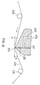
- a device called slot coater which has a slender slit opening 210 disposed at the lower end of a cavity 205 communicating with a hot-melt feed port 270a.
- This device is designed to apply the hot-melt 222 supplied in the cavity 205 on the surface of the nonwoven cloth 220 passing beneath while discharging it from the slit opening 210, and the nonwoven fabric which is the adherend is pressed against the slit opening by two backup rollers 225, 225 disposed at the lower side of the passage.
- the hot-melt was not completely transferred on the adherend depending on the type of the adherend, and the application became nonuniform, or part of the hot-melt was left over in the slot coater opening to laminate on the outer edge.
- this deposit exceeds a certain amount, it drops on the adherend and oozes (flows) out to the rear side of the adherend to stick to the roller for feeding the adherend or other parts to tear the adherend or cause stringing phenomenon.
- the hot-melt when the hot-melt is intermittently applied to the adherend with said conventional slot coater, the hot-melt does not stop to flow completely at coating intervals, thereby causing so-called stringing to give rise to streaky coats.
- the invention is composed as follows.
- a hot-melt applicator in accordance with a first embodiment of the invention having a slit-shaped opening formed at the lower end of the cavity through which hot-melt or other coating material is supplied, for applying said coating material on the adherend passing through the lower side of the opening, wherein an air nozzle for discharging air toward the outer edge of the opening is disposed.
- a hot-melt applicator in accordance with a second embodiment of the invention having a slit opening formed at the lower end of a cavity in which coating material such as hot-melt is supplied, for applying the coating material on an adherend passing beneath the opening, wherein an air nozzle for discharging air upward from the lower side of the adherend is disposed immediately beneath the opening.
- a hot-melt applicator in accordance with a third embodiment of the invention having a slit-shaped opening formed at the lower end of the cavity through which hot-melt or other coating material is supplied to apply said coating material to the adherend passing through the lower side of the opening, wherein a cylinder communicating with said cavity is provided, and a piston adapted to be moved back and forth is provided within the cylinder for decrease and increase of a pressure within the cavity.
- the coating material such as hot-melt supplied in the cavity is sent out from the slit opening at the lower end, and is applied on the adherend passing beneath in a width corresponding to the length of the opening.
- the coating material remaining at the outer edge of the opening is blown away to stick to the adherend. This air also cools the adherend an application on a material less resistant to heat may also be possible.
- the coating material such as hot-melt supplied in the cavity is sent out from the slit opening at the lower end, and is applied on the adherend passing at its lower side in a width corresponding to the length of the opening.
- air is discharged from the air nozzle located at the lower side of the passage of the adherend toward the opening, and the adherend is securely pressed against the opening with a proper force. Besides, this air also cools the adherend and it is also possible to apply to materials less resistant to heat.
- the coating material such as hot-melt supplied in the cavity is sent out of the slit-shaped opening at the lower end, and is applied to the adherend passing at its lower side in a width corresponding to the length of the opening.
- the prevention of leakage of the hot-melt can be effectively performed by moving the piston in a rearward direction to absorb the pressure in the cavity.
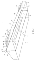
- Fig. 1 is a perspective view showing one embodiment of the hot-melt applicator in accordance with the first embodiment of the invention.
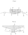
- Fig. 2 is a cross sectional view of Fig. 1.
- Fig. 3 is a view stating a principal part.
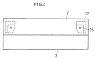
- Fig. 4 is a plan view of a block 3.
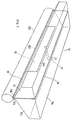
- Figs. 5 and 6 are views showing other embodiments.
- Fig. 7 is a perspective view showing an embodiment of the hot-melt applicator in accordance with the second embodiment of the invention and
- Fig. 8 is a cross sectional view of Fig. 7.
- Fig. 9 is a view stating a principal part.
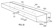
- Fig. 10 is a perspective view showing an embodiment of the hot-melt applicator in accordance with the third embodiment of the invention.
- Fig. 11 is a cross sectional view of Fig. 10
- Fig. 12 is a view stating a conventional slot coater device.
- the main body of an applicator 1 is composed of a pair of blocks 2, 3 disposed butt to butt, with an intervening shim 4, as shown in Fig. 1.
- the shim 4 is formed in a pi-shape with the opening downward, and the space formed by its concave notch 4a is a cavity 5. That is, the cavity 5 is a space opening downward being formed by two blocks 2, 3 and the shim 4, and has a volume as the product of the thickness of the shim 4 multiplied by the area of this notch.
- a feed hole 7 which projects into one block (cavity side block) 2 and has an opening in the upper surface is penetrating.
- the intermediate part of the protrusion 9 has a slender opening 10 in the width of the notch 4a of the shim 4.
- the other block (blind side block) 3 there are two air passage 15, 15 communicating from its top surface to a slop bottom 3b, and the lower end opening is the air nozzles 16, 16.
- a guide tool 17 for guiding the discharged air to the outer edge of the opening 10.
- the guide tool 17 is composed of a hook-shaped concealing part 17a affixed to the slope bottom 3b of the block 3 and plate part 17b extending parallel to the block bottom 3b from the concealing part, thereby forming a concave pocket 18, and the nozzle 16 is opened in this pocket 18.
- air nozzle 16 since the air nozzle 16 is provided in this applicator, air is discharged toward the outer edge 3a as shown in Figs. 3, 4 in the direction of arrow Y, and the hot-melt 22(A) which is going to deposit is pressed to the adherend 20 by this air, so that excessive deposit may be prevented. It is effective to discharge air continuously, but it may be also discharged intermittently. Moreover, since the adherend 20 and the hot-melt 22 are cooled by the discharged air, it is possible to apply to the adherend less resistant to heat, and the excessive flow of the sticking hot-melt is suppressed, and a more uniform application is possible.
- the air nozzle is formed as the opening end 30a of the air pipe 30, disposed at the send out (exit) side of the adherend.
- This air pipe 30 is connected to an air source which is not shown in the drawing.
- the pressure of the air jet should not be higher than required and, for example, in the case of a slot coater with the coating width of 250 to 400 mm, if the inside diameter of the air pipe 30 is 4 mm, dropping could not be prevented completely at the pressure of less than 0.5 kg/cm2G. It is desired to adjust and set the air pressure depending on the type of the hot melt and material of the adhesive, and it is preferred to install a reducing valve at the air supply side.
- Fig. 6 shows another embodiment in which the air nozzle is formed as a wide opening nozzle 40.
- the air supplied in the air inlet 40a is fine and is discharged as a laminar flow from the wide nozzle opening 40b.
- the air pressure may be set lower than in the foregoing embodiments. It is also easy to mount on an existing slot coater. It is evident that these applicators can be used in the application of other coating materials than the hot-melt paint and other adherends than the nonwoven fabric. As the air, other gases than compressed air may be also used.
- the main body of an applicator main body 51 is composed of a pair of blocks 52, 53 disposed butt to butt, with an intervening shim 54 at the junction.
- the shim 54 has an opening shaped downward in a pi-form, and the space formed by its concave notch 54a is a cavity 55. That is, the cavity 55 is a space opened downward formed by the two blocks 52, 53 and the shim 54, and possesses the volume as the product of the thickness of the shim 54 multiplied by the area of the notch.
- a feed hole 57 which pierces into one block (cavity side block) 52 and has an opening on its upper surface is communicating.
- This air blower 65 is a tube having a slit air nozzle 67 in the length nearly equal to the length of the opening 60 in the upper part, and the both ends are closed by plates.
- An air feed pipe 69 is connected to one of the ends. The other end of the air feed pipe 69 is connected to the air source which is not shown in the drawing.
- the air blower 65 may be either mounted on the main body 51a of the applicator by a support member 68 passing through the outer side in the width of the adherend, or may be supported separately from the applicator main body 61a. It is practically very convenient to make adjustable the height of the air nozzle 67 with respect to the opening 60.
- the pressure and amount of the air to be discharged may be enough as far as it is possible to press the adherend securely to the opening with a proper force, and optimum conditions may be set depending on the type of the adherend and the coating material and actual application condition. Accordingly, it is desirable to install a valve capable of adjusting the pressure and amount of air to be supplied in the air blower 65.
- the molten hot-melt 72 is supplied from the feed port 57 into the cavity 55, while the adherend 70 is continuously moved in the direction of arrow X, being guided by guide rollers 75, and an air stream at a proper pressure is discharged from the air nozzle 17.
- the slurry hot-melt 72 nearly fills up the cavity 55, and flows out downward from the opening 60, but since the adherend 70 is pressed against the opening 60 by the air discharged from the air nozzle 67, the flowing hot-melt 72 deposits on this adherend.
- the adherend 70 and the hot-melt 72 are cooled from the back side, so that it is possible to apply to the adherend which may be less resistant to heat. Moreover the excessive flow of the depositing hot-melt is suppressed, and more uniform application is possible.
- the air meanwhile, other gas than compressed air may be used as well. It is evident, moreover, that this applicator may be used in application of other coating materials than the hot-melt paint, or other adherends than nonwoven fabrics.
- the body of the applicator 101 is composed of a pair of blocks 102, 103 butted against each other with a shim 104 interposed between said blocks.
- Said shim 104 is in the form of a box with an open bottom having a cutout 104a, the space of which provides a cavity 105 for holding a hot-melt to be applied.
- the cavity 105 is formed by the pair of blocks 102, 103 and the shim 104 into a space formed with an opening in the lower portion.
- the space has a volume which is equal to the number obtained by the multiplication of the thickness of the shim 104 by the area of the cutout.
- the abutment between the two blocks 102 and 103 is formed integral with narrow plate-like downward projections 102a, 103a, which are combined with the lower end of the shim 104 to form an elongated square ridge 109.
- the intermediate portion of said ridge 109 provides an elongated opening 110 as wide as the cutout 104 of the shim 104.
- the cavity side block 102 is internally formed with an auxiliary cylindrical cavity 115 which communicates with said cavity 105 through a passageway 116 and also with a feeding opening 118 for hot-melt via a through-hole 117. Additionally, there is provided a cylinder portion 119 which communicates with the auxiliary cavity 115 into which a piston 121 is disposed slidably (moveable). Said piston 121 is moved back and forth relative to the auxiliary cavity 125 by a piston rod 123 which extends outwardly. A drive 125 for the piston 121 and a feeding valve 127 for hot-melt are connected with a control 130, so that the piston 121 may be moved backwardly and outwardly the instant the valve 127 is closed.
- the hot-melt 122 so transported is bonded to the adherend 120 due to the fact that the adherend 120 which has been introduced at an angle is being pressed to the area close to the outlet of the opening 110. Since the hot-melt 122 is liable to run off in an irregular manner at the outset of the coating operation, the piston 121 may be advanced so as to increase pressures within the cavities 115, 105. Such an increase of pressure causes a forcible extrusion of the hot-melt, thereby preventing the tendency toward the sticking of a small amount of the hot-melt to the adherend at the start of the coating operation.
- the valve 127 When the coating operation is stopped, the valve 127 is closed to cease supplying the hot-melt, and the piston 121 is swiftly moved backward. Then, a decrease of pressure will result in the cavities 115, 105, so that the hot-melt will be absorbed in a rearward direction, which avoids leakage from the opening 110. Consequently, if an intermittent coating takes place, the run-off and stop of the hot-melt can be accurately achieved, with the result that the intermittent coating operation at a high level in which no stringing occurs may be performed. It is apparent that this applicator may be used in the application of other coating materials than the hot-melt paint, and adherend other than the nonwoven fabric as well.
Applications Claiming Priority (6)
| Application Number | Priority Date | Filing Date | Title |
|---|---|---|---|
| JP26114790A JPH04141272A (ja) | 1990-09-28 | 1990-09-28 | ホットメルト等の塗工装置 |
| JP26114590A JPH04141270A (ja) | 1990-09-28 | 1990-09-28 | ホットメルト等の塗工装置 |
| JP261146/90 | 1990-09-28 | ||
| JP26114690A JPH04141271A (ja) | 1990-09-28 | 1990-09-28 | ホットメルト等の塗工装置 |
| JP261145/90 | 1990-09-28 | ||
| JP261147/90 | 1990-09-28 |
Publications (2)
| Publication Number | Publication Date |
|---|---|
| EP0477965A2 true EP0477965A2 (fr) | 1992-04-01 |
| EP0477965A3 EP0477965A3 (en) | 1992-05-27 |
Family
ID=27335004
Family Applications (1)
| Application Number | Title | Priority Date | Filing Date |
|---|---|---|---|
| EP19910116510 Withdrawn EP0477965A3 (en) | 1990-09-28 | 1991-09-27 | Hot-melt applicator |
Country Status (1)
| Country | Link |
|---|---|
| EP (1) | EP0477965A3 (fr) |
Cited By (1)
| Publication number | Priority date | Publication date | Assignee | Title |
|---|---|---|---|---|
| EP1925369A1 (fr) * | 2005-09-13 | 2008-05-28 | Sunstar Giken Kabushiki Kaisha | Applicateur de materiau de revetement hautement visqueux |
Citations (5)
| Publication number | Priority date | Publication date | Assignee | Title |
|---|---|---|---|---|
| GB894073A (en) * | 1959-10-28 | 1962-04-18 | Du Pont | Improvements relating to web coating processes and apparatus |
| GB1497662A (en) * | 1975-10-31 | 1978-01-12 | Molins Ltd | Devices for applying liquids such as adhesives to a moving web |
| FR2553305A1 (fr) * | 1983-10-17 | 1985-04-19 | Waertsilae Oy Ab | Dispositif de revetement a couteau a air |
| EP0329424A2 (fr) * | 1988-02-17 | 1989-08-23 | Konica Corporation | Appareil de revêtement |
| WO1989010206A1 (fr) * | 1988-04-20 | 1989-11-02 | Lenhardt Maschinenbau Gmbh | Dispositif distributeur de substances compressibles pateuses a viscosite elevee |
-
1991
- 1991-09-27 EP EP19910116510 patent/EP0477965A3/en not_active Withdrawn
Patent Citations (5)
| Publication number | Priority date | Publication date | Assignee | Title |
|---|---|---|---|---|
| GB894073A (en) * | 1959-10-28 | 1962-04-18 | Du Pont | Improvements relating to web coating processes and apparatus |
| GB1497662A (en) * | 1975-10-31 | 1978-01-12 | Molins Ltd | Devices for applying liquids such as adhesives to a moving web |
| FR2553305A1 (fr) * | 1983-10-17 | 1985-04-19 | Waertsilae Oy Ab | Dispositif de revetement a couteau a air |
| EP0329424A2 (fr) * | 1988-02-17 | 1989-08-23 | Konica Corporation | Appareil de revêtement |
| WO1989010206A1 (fr) * | 1988-04-20 | 1989-11-02 | Lenhardt Maschinenbau Gmbh | Dispositif distributeur de substances compressibles pateuses a viscosite elevee |
Cited By (2)
| Publication number | Priority date | Publication date | Assignee | Title |
|---|---|---|---|---|
| EP1925369A1 (fr) * | 2005-09-13 | 2008-05-28 | Sunstar Giken Kabushiki Kaisha | Applicateur de materiau de revetement hautement visqueux |
| EP1925369A4 (fr) * | 2005-09-13 | 2014-01-15 | Sunstar Engineering Inc | Applicateur de materiau de revetement hautement visqueux |
Also Published As
| Publication number | Publication date |
|---|---|
| EP0477965A3 (en) | 1992-05-27 |
Similar Documents
| Publication | Publication Date | Title |
|---|---|---|
| US4774109A (en) | Method and apparatus for applying narrow, closely spaced beads of viscous liquid to a substrate | |
| US4844004A (en) | Method and apparatus for applying narrow, closely spaced beads of viscous liquid to a substrate | |
| US5524828A (en) | Apparatus for applying discrete foam coatings | |
| US4735169A (en) | Adhesive applicator assembly | |
| JP2653784B2 (ja) | 長い帯板品を塗装するための装置および方法 | |
| US3113884A (en) | Coating means and method | |
| KR840001441A (ko) | 블레이드 형식의 파운틴 코우터와 그 방법 | |
| US4503804A (en) | Edge seal assembly for paper coating apparatus | |
| US20060068113A1 (en) | Method of applying viscous fluid material and apparatus therefor | |
| US4534309A (en) | Paper coating apparatus | |
| EP2441528B1 (fr) | Buse pour dispositif de revêtement d'adhésif | |
| JP4529060B2 (ja) | シート状等の被塗物に液体を塗布する装置及び方法 | |
| JP2006334512A (ja) | 塗膜保護材塗布方法及び同塗布ノズル | |
| JPH06190324A (ja) | 塗工装置 | |
| JPH08508676A (ja) | ペーパーウェブ上の被覆の途切れの最小化方法 | |
| US7556692B2 (en) | Device for coating a continuous web of material | |
| JP2821832B2 (ja) | ホットメルト接着剤塗布装置 | |
| JPH07110346B2 (ja) | 塗工装置及び巻取紙塗布方法 | |
| EP0477965A2 (fr) | Applicateur pour produit thermofusible | |
| US4859507A (en) | High speed paper coaters | |
| EP0604821B1 (fr) | Technique d'induction à la perle | |
| KR100324050B1 (ko) | 표면에 코팅액을 도포하는 장치 및 그 방법 | |
| JPS6097068A (ja) | 移動するウェブ材の被覆用の塗布装置 | |
| US3203393A (en) | Apparatus for applying stripes of low viscosity coating material | |
| JP2992812B2 (ja) | ホットメルト接着剤塗布装置およびホットメルト接着剤塗布方法 |
Legal Events
| Date | Code | Title | Description |
|---|---|---|---|
| PUAI | Public reference made under article 153(3) epc to a published international application that has entered the european phase |
Free format text: ORIGINAL CODE: 0009012 |
|
| AK | Designated contracting states |
Kind code of ref document: A2 Designated state(s): DE FR GB IT NL SE |
|
| PUAL | Search report despatched |
Free format text: ORIGINAL CODE: 0009013 |
|
| 17P | Request for examination filed |
Effective date: 19920313 |
|
| AK | Designated contracting states |
Kind code of ref document: A3 Designated state(s): DE FR GB IT NL SE |
|
| 17Q | First examination report despatched |
Effective date: 19931028 |
|
| STAA | Information on the status of an ep patent application or granted ep patent |
Free format text: STATUS: THE APPLICATION IS DEEMED TO BE WITHDRAWN |
|
| 18D | Application deemed to be withdrawn |
Effective date: 19940308 |