EP0477918A1 - Eurouleur à verrouillage d'urgence silencieux - Google Patents
Eurouleur à verrouillage d'urgence silencieux Download PDFInfo
- Publication number
- EP0477918A1 EP0477918A1 EP91116364A EP91116364A EP0477918A1 EP 0477918 A1 EP0477918 A1 EP 0477918A1 EP 91116364 A EP91116364 A EP 91116364A EP 91116364 A EP91116364 A EP 91116364A EP 0477918 A1 EP0477918 A1 EP 0477918A1
- Authority
- EP
- European Patent Office
- Prior art keywords
- stand
- man
- emergency locking
- housing
- locking type
- Prior art date
- Legal status (The legal status is an assumption and is not a legal conclusion. Google has not performed a legal analysis and makes no representation as to the accuracy of the status listed.)
- Withdrawn
Links
Images


Classifications
-
- B—PERFORMING OPERATIONS; TRANSPORTING
- B60—VEHICLES IN GENERAL
- B60R—VEHICLES, VEHICLE FITTINGS, OR VEHICLE PARTS, NOT OTHERWISE PROVIDED FOR
- B60R22/00—Safety belts or body harnesses in vehicles
- B60R22/34—Belt retractors, e.g. reels
- B60R22/36—Belt retractors, e.g. reels self-locking in an emergency
- B60R22/405—Belt retractors, e.g. reels self-locking in an emergency responsive to belt movement and vehicle movement
-
- B—PERFORMING OPERATIONS; TRANSPORTING
- B60—VEHICLES IN GENERAL
- B60R—VEHICLES, VEHICLE FITTINGS, OR VEHICLE PARTS, NOT OTHERWISE PROVIDED FOR
- B60R22/00—Safety belts or body harnesses in vehicles
- B60R22/34—Belt retractors, e.g. reels
Definitions
- the present invention relates in general to seat belt retractors for use in a seat belt system installed in a motor vehicle, and more particularly to seat belt retractors of an emergency locking type which arrests the drawing of the seat belt therefrom upon sensing abnormal deceleration due to a vehicle collision or the like. More specifically, the present invention is concerned with the emergency locking type retractors which are constructed to produce less noise during their use.
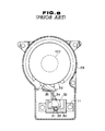
- a typical emergency locking type seat belt system will be described with an aid of Fig. 8 which shows a conventional emergency locking type retractor.
- the seat belt system comprises generally a seat belt proper, a through ring with a tongue, an emergency locking type retractor and a belt anchor with a buckle.
- the seat belt proper extends upward from a lower outside portion of a vehicle cabin, turns back at a belt holder fixed to a higher outside portion of the cabin and extends downward to be retracted by the retractor which is mounted to the lower outside portion of the cabin.
- the through ring has the seat belt proper slidably passed therethrough.
- the belt anchor is mounted to a lower inside portion of the vehicle cabin.
- the emergency locking type retractor comprises a housing 29 fixed to the vehicle body, a belt retracting shaft 100 rotatably disposed in the housing 29 and having the seat belt proper wound thereabout, a coil spring (not shown) for biasing the shaft 100 in a direction to retract the seat belt proper, and a locking device which locks the belt retracting shaft 100 upon sensing abnormal deceleration of the vehicle.
- the locking device comprises a ratchet wheel 36 which is coaxially secured to the belt retracting shaft 100 to rotate therewith. Teeth of the ratchet wheel 36 are denoted by numerals 37.
- Located near the ratchet wheel 36 is a stand-man holder 30 which is tightly secured to the housing 29 through a bracket 11.
- the stand-man holder 30 has a small recess 31 at its bottom.
- a stand-man 32 (or weight) is loosely received in the holder 30 in such a manner that a lower projection 33 of the stand-man 32 is put in the small recess 31.
- the stand-man 32 has a tapered recess at a head portion.
- a bent lever 34 which is pivotally connected through a pivot pin (no numeral) to the housing 29.
- One arm portion of the bent lever 34 is slidably engaged with the tapered recess of the stand-man 32 and the other arm portion 35 of the same is shaped like a pawl.
- the stand-man 32 stands upright as shown by the solid line. Under this condition, the pawl of the bent lever 34 is kept away from the ratchet wheel 36, and thus, the belt retracting shaft of the belt retractor is permitted to rotate in both directions.
- the stand-man 32 is forced to vibrate finely due to the vibration of the vehicle.
- the fine vibration of the stand-man 32 causes beating of the same against the stand-man holder 30 thereby generating noises.
- the vibration of the stand-man 32 induces vibration of the bent lever 34, which also causes generation of noises.
- an emergency locking type retractor for a seat belt.
- the retractor comprises a housing; a shaft rotatably received in the housing for selectively winding and unwinding the seat belt thereabout and therefrom; emergency locking means including a stand-man holder tightly held by the housing, a stand-man operatively held by the holder and a pivotal lever member, the pivotal lever member locking the shaft against rotation in a direction to draw the seat belt therefrom when the stand-man is inclined relative to the stand-man holder; and a structure mounted to the housing to define a sound insulating enclosed space in which the stand-man and the pivotal lever member are installed.
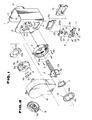
- FIG. 1 there is shown an emergency locking type retractor of the present invention.
- Designated by numeral 1 is a housing which has aligned openings 1 and 1 at its side walls 1 x and 1y.
- the side wall 1x is formed with a plurality of equally spaced pawls 1 a about the opening 1 b.
- a belt retracting shaft 2 is rotatably received in the aligned openings 1 and 1 of the housing 1.
- a spring case 1 is mounted to the side wall 1y of the housing 1. Within the case 1 d, there is installed a spiral spring for biasing the shaft 2 in a direction to retract a seat belt (not shown).
- a circular case 4 is mounted to the other side wall 1x of the housing 1.
- the circular case 4 is formed with a plurality of arcuate slots 4a through which the pawls 1 a of the housing 1 are inserted into the case 4.
- a ratchet wheel 8 which is coaxially disposed about the belt retracting shaft 2 in an after-mentioned manner.
- the circular case 4 has at its cylindrical side wall a rectangular opening 4b through which one arm portion 20a of an after- described bent lever 20 is inserted into the case 4. That is, the arm portion 20a is operatively engageable with external teeth 8a of the ratchet wheel 8 which is installed in the circular case 4.
- the belt retracting shaft 2 has at one end a smaller diameter pin portion 2a.
- a shaft wheel 3 is coaxially connected to the belt retracting shaft 2 having the pin portion 2a exposed to outside.
- the shaft wheel 3 is formed at its periphery with a plurality of equally spaced pawls 3a. Each pawl 3a is bent toward the axis of the pin portion 2a and inclined somewhat in a circumferential direction, as shown.
- the ratchet wheel 8 is coaxially and pivotally disposed about the pin portion 2a of the shaft 2 having an annular spring 7, a lock plate 6 and an inertia plate 10 operatively interposed between the ratchet wheel 8 and the shaft wheel 3.
- the lock plate 6 is formed with external teeth 6a which are engageable with both the pawls 3a of the shaft wheel 3 and the pawls 1 a of the housing 1, and internal teeth 6b which are engageable with cam surfaces 8b (see Fig. 2) formed in the ratchet wheel 8. That is, as is seen from Fig. 2, the ratchet wheel 8 is formed with a circular recess in which the cam surfaces 8b are defined. The external teeth 8a of the ratchet wheel 8 are rounded.
- the inertia plate 10 is oval in shape and has a circular opening 10a. The inertia plate 10 is rotatably received in the recess of the ratchet wheel 8 having the circular opening 10a thereof coaxially disposed about the cam surfaces 8b of the ratchet wheel 8.
- the ratchet wheel 8 is formed at its diametrically opposed portions with rectangular openings 8d through which the interior of the ratchet wheel 8 and outside of the same are communicated.
- Each rectangular opening 8d receives therein a pawl member 9 which is pivotally connected to a stud 8c formed on the ratchet wheel 8.
- the pawl member 9 is biased radially inward by a plate spring 9a incorporated therewith.
- the pawl member 9 has a projection 9b which is slidably engageable with a peripheral cam portion of the inertia plate 10.
- the deceleration sensor 5 comprises a stand-man holder 5c which is secured through its bracket 11 to a lower outside surface of the side wall 1x of the housing 1 with an interposal of a rectangular frame 5b therebetween.
- the side wall 1x is formed with a rectangular opening 1 through which a part of the stand-man holder 5c is projected into the housing 1.
- two bolts 5d are used for the connection of the stand-man holder 5c and the frame 5b to the side wall 1x.
- a stand-man 5e (or weight) is operatively received in the holder 5c in a manner similar to that as has been described in the conventional emergency locking type retractor of Fig. 5.
- a bent lever 20 is pivotally supported by two supports 13 formed on the stand-man holder 5c.
- the bent lever 20 comprises the aforementioned one arm portion 20a projectable into the circular case 4 and the other arm portion 20b slidably engaged with a tapered recess 5f of the stand-man 5e.
- a dust cover 15 is fixed to an inside surface of the side wall 1x of the housing 1 to cover the rectangular opening 1 c.
- a sensor cover 16 is fixed to the outside surface of the side wall 1 x to cover the parts 4, 3, 7, 6, 10, and 8, and their associated parts.
- the stand-man 5e stands upright like in the case of the above-mentioned conventional emergency locking type retractor. Under this condition, the arm portion 20a is kept away from the ratchet wheel 8, and thus, the belt retracting shaft 2 is permitted to rotate in both directions. However, when, due to a vehicle collision or the like, abnormal shock is sensed by the stand-man 5e, the same is inclined to cause the bent lever 20 to assume its operative position wherein the arm portion 20a abuts one of the teeth 8a of the ratchet wheel 8. Under this condition, the belt retracting shaft 2 is locked against rotation in the direction to draw the belt from the retractor.
- the following measure is employed for minimizing or lessening the noises generated by the stand-man 5e.
- the stand-man holder 5c substantially consists of a box part 12 of a double wall construction, the bracket 11 and the supports 13, which are combined to constitute a united structure.
- the stand-man holder 5c is constructed of fiber-reinforced engineering plastics or the like.
- the box part 12 comprises outer and inner walls between which a sound insulating air space 14 is defined.
- the dust cover 15 is also of a double wall construction, which comprises outer and inner walls 15a and 15b between which a sound insulating air space 15c is defined.
- the sensor cover 16 has a double bottom which comprises outer and inner walls 16a and 16b between which a sound insulating air space 16c is defined.
- these duct cover 15 and the sensor cover 16 are constructed of fiber-reinforced engineering plastics or the like.
- the air spaces 14, 15c and 16c of the stand-man holder 5c, the dust cover 15 and the sensor cover 16 may be filled with a sound insulating material, such as, fixed oil, glass fiber, asphalt sheet, rubber tips, plastic tips or the like.
- the box part 12 of the stand-man holder 5c, the dust cover 15 and the sensor cover 16, which are of a double wall construction, constitute a sound insulating enclosed space in which the stand-man 5e and the bent lever 20 are operatively installed.
- the enclosed space shuts out or at least minimizes the noise propagation to outside of the retractor.
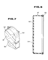
- FIGs. 6 and 7 there is shown a modified sensor cover 16' which is employable in the invention.
- the modified sensor cover 16' has around its mouth portion an elastomeric seal member 50 detachably attached thereto.
- the seal member 50 is tightly compressed therebetween.
- the sensor cover 16' has on an outer surface of its bottom two X-shaped beams 52 and 54. With these beams 52 and 54, the rigidity of the sensor cover 16' is increased.
- the modified sensor cover 16' is employed in place of the aforementioned sensor cover 16, the sound insulating effect is much assured.
Applications Claiming Priority (4)
| Application Number | Priority Date | Filing Date | Title |
|---|---|---|---|
| JP101167/90U | 1990-09-27 | ||
| JP10116690U JPH0457467U (fr) | 1990-09-27 | 1990-09-27 | |
| JP101166/90U | 1990-09-27 | ||
| JP10116790U JPH0457468U (fr) | 1990-09-27 | 1990-09-27 |
Publications (1)
| Publication Number | Publication Date |
|---|---|
| EP0477918A1 true EP0477918A1 (fr) | 1992-04-01 |
Family
ID=26442082
Family Applications (1)
| Application Number | Title | Priority Date | Filing Date |
|---|---|---|---|
| EP91116364A Withdrawn EP0477918A1 (fr) | 1990-09-27 | 1991-09-25 | Eurouleur à verrouillage d'urgence silencieux |
Country Status (2)
| Country | Link |
|---|---|
| US (1) | US5209421A (fr) |
| EP (1) | EP0477918A1 (fr) |
Cited By (9)
| Publication number | Priority date | Publication date | Assignee | Title |
|---|---|---|---|---|
| EP0581488A1 (fr) * | 1992-07-25 | 1994-02-02 | Alliedsignal Limited | Amélioration aux mécanismes pour ceinture de sécurité à blocage d'urgence |
| DE102006033543A1 (de) * | 2006-07-20 | 2008-07-03 | Autoliv Development Ab | Selbstsperrender Gurtaufroller |
| DE102007020192A1 (de) * | 2007-04-28 | 2008-10-30 | Dr. Ing. H.C. F. Porsche Aktiengesellschaft | Kappe für eine Sicherheitsgurt-Aufrollvorrichtung |
| WO2009046991A1 (fr) * | 2007-10-13 | 2009-04-16 | Autoliv Development Ab | Enrouleur de ceinture autobloquant |
| WO2011015318A1 (fr) * | 2009-08-07 | 2011-02-10 | Autoliv Development Ab | Enrouleur de ceinture autobloquant |
| WO2013071928A2 (fr) * | 2011-11-18 | 2013-05-23 | Takata AG | Capteur |
| WO2016040303A1 (fr) * | 2014-09-09 | 2016-03-17 | Key Safety Systems, Inc. | Enrouleur muni de protection contre la boue et présentant une réduction des vibrations |
| CN104768807B (zh) * | 2012-09-19 | 2017-09-12 | Trw汽车股份有限公司 | 安全带卷收器壳体罩和安全带卷收器 |
| DE102012206465B4 (de) | 2011-04-22 | 2022-09-15 | Joyson Safety Systems Acquisition Llc | Aufrollvorrichtung für Sitzgurt |
Families Citing this family (8)
| Publication number | Priority date | Publication date | Assignee | Title |
|---|---|---|---|---|
| JP3153309B2 (ja) * | 1992-01-30 | 2001-04-09 | タカタ株式会社 | シートベルトリトラクタ |
| US6082655A (en) * | 1998-11-04 | 2000-07-04 | Trw Vehicle Safety Systems Inc. | Noise suppression cover for belt webbing retractor |
| US6419178B1 (en) * | 2000-07-19 | 2002-07-16 | Breed Automotive Technology, Inc. | Seat belt retractor with integrally formed frame |
| US7300013B2 (en) * | 2005-02-16 | 2007-11-27 | Key Safety Systems, Inc. | Seat belt retractor with overmolded inertia sensor mass |
| US9150190B2 (en) | 2011-03-02 | 2015-10-06 | Indiana Mills & Manufacturing, Inc. | Hermetically sealed locking retractor |
| CA2841618A1 (fr) * | 2011-08-03 | 2013-02-07 | Amsafe Commercial Products, Inc. | Retracteurs de sangle de ceinture de securite et systemes et procedes associes |
| US10166947B2 (en) * | 2015-10-15 | 2019-01-01 | Shield Restraint Systems, Inc. | Sealed web retractors for personal restraint systems and associated systems and methods |
| US10562489B2 (en) * | 2018-03-01 | 2020-02-18 | Ford Global Technologies, Llc | Cover for a seatbelt retractor assembly to reduce audible noise and a seatbelt retractor assembly including the cover |
Citations (4)
| Publication number | Priority date | Publication date | Assignee | Title |
|---|---|---|---|---|
| US3287063A (en) * | 1964-08-07 | 1966-11-22 | Arthur S Nicholas | Retractor housing |
| DE3019275A1 (de) * | 1980-05-21 | 1981-11-26 | Volkswagenwerk Ag, 3180 Wolfsburg | Sicherheitseinrichtung |
| DE3140270A1 (de) * | 1981-10-10 | 1983-04-28 | Autoflug Gmbh, 2084 Rellingen | Kraftfahrzeug-rahmenteil mit gurtaufroller und strammvorrichtung |
| DE3205515A1 (de) * | 1981-11-30 | 1983-06-09 | Repa Feinstanzwerk Gmbh, 7071 Alfdorf | Vorrichtung zum blockieren einer aufrolleinrichtung fuer sicherheitsgurte |
Family Cites Families (2)
| Publication number | Priority date | Publication date | Assignee | Title |
|---|---|---|---|---|
| JPS57173756U (fr) * | 1981-04-25 | 1982-11-02 | ||
| JPS59150461U (ja) * | 1983-03-30 | 1984-10-08 | 富士機工株式会社 | エマ−ジエンシイ・ロツキング・リトラクタ |
-
1991
- 1991-09-20 US US07/763,247 patent/US5209421A/en not_active Expired - Fee Related
- 1991-09-25 EP EP91116364A patent/EP0477918A1/fr not_active Withdrawn
Patent Citations (4)
| Publication number | Priority date | Publication date | Assignee | Title |
|---|---|---|---|---|
| US3287063A (en) * | 1964-08-07 | 1966-11-22 | Arthur S Nicholas | Retractor housing |
| DE3019275A1 (de) * | 1980-05-21 | 1981-11-26 | Volkswagenwerk Ag, 3180 Wolfsburg | Sicherheitseinrichtung |
| DE3140270A1 (de) * | 1981-10-10 | 1983-04-28 | Autoflug Gmbh, 2084 Rellingen | Kraftfahrzeug-rahmenteil mit gurtaufroller und strammvorrichtung |
| DE3205515A1 (de) * | 1981-11-30 | 1983-06-09 | Repa Feinstanzwerk Gmbh, 7071 Alfdorf | Vorrichtung zum blockieren einer aufrolleinrichtung fuer sicherheitsgurte |
Cited By (25)
| Publication number | Priority date | Publication date | Assignee | Title |
|---|---|---|---|---|
| EP0581488A1 (fr) * | 1992-07-25 | 1994-02-02 | Alliedsignal Limited | Amélioration aux mécanismes pour ceinture de sécurité à blocage d'urgence |
| EP0795447A2 (fr) * | 1992-07-25 | 1997-09-17 | Alliedsignal Limited | Amélioration aux mécanismes pour ceiture de sécurité de passager à blocage d'urgence |
| EP0795447A3 (fr) * | 1992-07-25 | 1998-10-21 | Alliedsignal Limited | Amélioration aux mécanismes pour ceiture de sécurité de passager à blocage d'urgence |
| DE102006033543A1 (de) * | 2006-07-20 | 2008-07-03 | Autoliv Development Ab | Selbstsperrender Gurtaufroller |
| DE102006033543B4 (de) | 2006-07-20 | 2019-06-19 | Autoliv Development Ab | Selbstsperrender Gurtaufroller |
| DE102007020192A1 (de) * | 2007-04-28 | 2008-10-30 | Dr. Ing. H.C. F. Porsche Aktiengesellschaft | Kappe für eine Sicherheitsgurt-Aufrollvorrichtung |
| US7883114B2 (en) | 2007-04-28 | 2011-02-08 | Dr. Ing. H.C. F. Porsche Aktiengesellschaft | Cap for a seat belt retractor |
| DE102007049200A1 (de) * | 2007-10-13 | 2009-04-16 | Autoliv Development Ab | Selbstsperrender Gurtaufroller |
| DE102007049200B4 (de) | 2007-10-13 | 2023-10-05 | Autoliv Development Ab | Selbstsperrender Gurtaufroller |
| WO2009046991A1 (fr) * | 2007-10-13 | 2009-04-16 | Autoliv Development Ab | Enrouleur de ceinture autobloquant |
| WO2011015318A1 (fr) * | 2009-08-07 | 2011-02-10 | Autoliv Development Ab | Enrouleur de ceinture autobloquant |
| DE102009036516A1 (de) * | 2009-08-07 | 2011-02-10 | Autoliv Development Ab | Selbstsperrender Gurtaufroller |
| KR20120052279A (ko) * | 2009-08-07 | 2012-05-23 | 아우토리브 디벨롭먼트 아베 | 셀프 로킹 벨트 리트랙터 |
| US9073514B2 (en) | 2009-08-07 | 2015-07-07 | Autoliv Development Ab | Self-locking seat belt retractor |
| DE102009036516B4 (de) | 2009-08-07 | 2021-07-15 | Autoliv Development Ab | Selbstsperrender Gurtaufroller |
| KR101702543B1 (ko) | 2009-08-07 | 2017-02-03 | 아우토리브 디벨롭먼트 아베 | 셀프 로킹 벨트 리트랙터 |
| DE102012206465B4 (de) | 2011-04-22 | 2022-09-15 | Joyson Safety Systems Acquisition Llc | Aufrollvorrichtung für Sitzgurt |
| WO2013071928A3 (fr) * | 2011-11-18 | 2013-07-11 | Takata AG | Capteur |
| US9409547B2 (en) | 2011-11-18 | 2016-08-09 | Takata AG | Sensor |
| WO2013071928A2 (fr) * | 2011-11-18 | 2013-05-23 | Takata AG | Capteur |
| CN104768807B (zh) * | 2012-09-19 | 2017-09-12 | Trw汽车股份有限公司 | 安全带卷收器壳体罩和安全带卷收器 |
| DE102012018477B4 (de) | 2012-09-19 | 2024-01-25 | Zf Automotive Germany Gmbh | Gurtaufroller |
| US20170291570A1 (en) * | 2014-09-09 | 2017-10-12 | Key Safety Systems, Inc. | Retractor with Mud Shield and Vibration Reduction |
| US10464522B2 (en) | 2014-09-09 | 2019-11-05 | Key Safety Systems, Inc. | Retractor with mud shield and vibration reduction |
| WO2016040303A1 (fr) * | 2014-09-09 | 2016-03-17 | Key Safety Systems, Inc. | Enrouleur muni de protection contre la boue et présentant une réduction des vibrations |
Also Published As
| Publication number | Publication date |
|---|---|
| US5209421A (en) | 1993-05-11 |
Similar Documents
| Publication | Publication Date | Title |
|---|---|---|
| US5209421A (en) | Noiseless emergency locking type retractor | |
| US6722601B2 (en) | Seat belt retractor with integrally formed frame | |
| US6443382B1 (en) | Vehicular seatbelt retractor | |
| JP4627229B2 (ja) | シートベルト用リトラクター | |
| JPH07101311A (ja) | 乗客用安全ベルト緊急固定装置 | |
| CA1112227A (fr) | Mecanisme de verrouillage et bobine pour dispositif de rappel | |
| US3831878A (en) | Restraint belt retractor | |
| USRE36190E (en) | Seat belt tightening device | |
| US7090304B2 (en) | Retractor having vehicle sensitive sensor disabling mechanism | |
| US6082655A (en) | Noise suppression cover for belt webbing retractor | |
| JP3996779B2 (ja) | シートベルト用リトラクター | |
| EP0543520B1 (fr) | Rétracteur de ceinture de sécurité comportant un mécanisme de suppression de cliquetis | |
| JPH081985Y2 (ja) | プリローダセンサ | |
| JPS6154615B2 (fr) | ||
| CN114667243B (zh) | 具有车辆传感器的安全带卷收器 | |
| US4244537A (en) | Adjustable sensor responsive to vehicle acceleration | |
| US4905928A (en) | Locking apparatus for webbing retractor | |
| JP2006213156A (ja) | 保持構造及びウエビング巻取装置 | |
| JPH03279058A (ja) | シートベルトのリトラクタ | |
| US4173318A (en) | Webbing retractor in safety seatbelt system | |
| JPH0744515Y2 (ja) | ウエビング巻取装置 | |
| EP0919441A2 (fr) | Système de retenue d'un occupant de véhicule | |
| JP3426392B2 (ja) | ウエビング巻取装置 | |
| JPH0314444Y2 (fr) | ||
| JP3437486B2 (ja) | ウエビング巻取装置 |
Legal Events
| Date | Code | Title | Description |
|---|---|---|---|
| PUAI | Public reference made under article 153(3) epc to a published international application that has entered the european phase |
Free format text: ORIGINAL CODE: 0009012 |
|
| 17P | Request for examination filed |
Effective date: 19910925 |
|
| AK | Designated contracting states |
Kind code of ref document: A1 Designated state(s): DE FR GB IT |
|
| STAA | Information on the status of an ep patent application or granted ep patent |
Free format text: STATUS: THE APPLICATION HAS BEEN WITHDRAWN |
|
| 18W | Application withdrawn |
Withdrawal date: 19930317 |