EP0477713B1 - Dispositif pour fixer notamment une pièce de construction tubulaire à une paroi ou un élément similaire - Google Patents
Dispositif pour fixer notamment une pièce de construction tubulaire à une paroi ou un élément similaire Download PDFInfo
- Publication number
- EP0477713B1 EP0477713B1 EP91115684A EP91115684A EP0477713B1 EP 0477713 B1 EP0477713 B1 EP 0477713B1 EP 91115684 A EP91115684 A EP 91115684A EP 91115684 A EP91115684 A EP 91115684A EP 0477713 B1 EP0477713 B1 EP 0477713B1
- Authority
- EP
- European Patent Office
- Prior art keywords
- expandable
- expanding
- expandable portion
- threaded bolt
- segments
- Prior art date
- Legal status (The legal status is an assumption and is not a legal conclusion. Google has not performed a legal analysis and makes no representation as to the accuracy of the status listed.)
- Expired - Lifetime
Links
- 229910000831 Steel Inorganic materials 0.000 claims description 5
- 239000010959 steel Substances 0.000 claims description 5
- 230000002093 peripheral effect Effects 0.000 claims 3
- 230000037431 insertion Effects 0.000 abstract 1
- 238000003780 insertion Methods 0.000 abstract 1
- 239000002184 metal Substances 0.000 description 11
- 238000003892 spreading Methods 0.000 description 7
- 230000007480 spreading Effects 0.000 description 7
- 238000010276 construction Methods 0.000 description 4
- 238000004904 shortening Methods 0.000 description 4
- 230000003068 static effect Effects 0.000 description 4
- 230000008901 benefit Effects 0.000 description 3
- 230000008859 change Effects 0.000 description 3
- 230000000694 effects Effects 0.000 description 3
- 230000004323 axial length Effects 0.000 description 2
- 230000003247 decreasing effect Effects 0.000 description 2
- 238000001746 injection moulding Methods 0.000 description 2
- 230000003993 interaction Effects 0.000 description 2
- 239000000463 material Substances 0.000 description 2
- 238000000034 method Methods 0.000 description 2
- 230000008569 process Effects 0.000 description 2
- 238000013459 approach Methods 0.000 description 1
- 230000000712 assembly Effects 0.000 description 1
- 238000000429 assembly Methods 0.000 description 1
- 238000005452 bending Methods 0.000 description 1
- 230000007423 decrease Effects 0.000 description 1
- 230000001934 delay Effects 0.000 description 1
- 230000001066 destructive effect Effects 0.000 description 1
- 238000005304 joining Methods 0.000 description 1
- 238000004519 manufacturing process Methods 0.000 description 1
- 238000003801 milling Methods 0.000 description 1
- 238000009877 rendering Methods 0.000 description 1
- 230000000717 retained effect Effects 0.000 description 1
Images


Classifications
-
- F—MECHANICAL ENGINEERING; LIGHTING; HEATING; WEAPONS; BLASTING
- F16—ENGINEERING ELEMENTS AND UNITS; GENERAL MEASURES FOR PRODUCING AND MAINTAINING EFFECTIVE FUNCTIONING OF MACHINES OR INSTALLATIONS; THERMAL INSULATION IN GENERAL
- F16B—DEVICES FOR FASTENING OR SECURING CONSTRUCTIONAL ELEMENTS OR MACHINE PARTS TOGETHER, e.g. NAILS, BOLTS, CIRCLIPS, CLAMPS, CLIPS OR WEDGES; JOINTS OR JOINTING
- F16B12/00—Jointing of furniture or the like, e.g. hidden from exterior
- F16B12/40—Joints for furniture tubing
- F16B12/42—Joints for furniture tubing connecting furniture tubing to non-tubular parts
-
- A—HUMAN NECESSITIES
- A47—FURNITURE; DOMESTIC ARTICLES OR APPLIANCES; COFFEE MILLS; SPICE MILLS; SUCTION CLEANERS IN GENERAL
- A47H—FURNISHINGS FOR WINDOWS OR DOORS
- A47H1/00—Curtain suspension devices
- A47H1/10—Means for mounting curtain rods or rails
- A47H1/102—Means for mounting curtain rods or rails for mounting curtain rods
-
- A—HUMAN NECESSITIES
- A47—FURNITURE; DOMESTIC ARTICLES OR APPLIANCES; COFFEE MILLS; SPICE MILLS; SUCTION CLEANERS IN GENERAL
- A47K—SANITARY EQUIPMENT NOT OTHERWISE PROVIDED FOR; TOILET ACCESSORIES
- A47K3/00—Baths; Douches; Appurtenances therefor
- A47K3/28—Showers or bathing douches
- A47K3/38—Curtain arrangements
Definitions
- the invention relates to a device of the type specified in the preamble of claim 1.
- Devices of this type are primarily used to make objects, such as swing door handles, handle bars, curtain or shower curtain bars, railings, handrails, trade fair and exhibition stands or the like at individual, preselected locations on a wall or made of tubular or rod-shaped and knot-shaped components, preferably modular assemblies Anchor door, ceiling, ground or the like. It often happens that the components have a slightly longer or shorter length than is actually required or is desirable due to the already installed mounting holes. This applies, for example, to the assembly of curtain rods, in particular shower curtain rods, the pipe or rod elements of which can have so many different lengths that the manufacturer and dealer can only produce and / or keep elements with a few standardized lengths. In such cases, it is usually necessary or at least desirable to shorten or lengthen the pipes or rods at the construction site to the length required in the individual case.
- this known device cannot withstand such high static loads, as is often required for the above-mentioned objects, that a relative rotation of these two parts to one another is required to establish or release the connection between the holding part and the component, and that the described one Device is only suitable for components with receiving openings that have a non-circular cross-section.
- the last-mentioned special feature makes the device of the type mentioned at the outset unusable for most of the objects mentioned, the receiving openings of which are all cylindrical because they are located at the ends of cylindrical tubes, which are made, for example, of steel, of plastic-coated or plastic-coated steel or just consist of plastic.
- devices of a second type are therefore used, for example holding parts in the form of fastening bolts that can be used on one or both sides of a wall or door and are pinned to the respective component (DE-U-71 17 167) to the components welded rosette lower parts (DE-A-31 32 855) or of rosette lower parts with approaches that are adapted to special, formed in the receiving openings and screwed to them (DE-C-24 60 382).
- Such devices are fully satisfactory from a static point of view and can also be used with ease in the presence of cylindrical receiving openings, but, in contrast to the devices of the first-mentioned type, have the essential disadvantage that a change in length of the pipe or rod and if necessary is necessary Node elements is very complicated.
- the invention is therefore based on the object of improving the device of the type described first in that the connection between the holding part and the component can still be easily produced and released again, but that statically demanding objects are still produced and components with receiving openings are provided who have circular cross-sections.
- the device should in particular be designed so that the components can be extended or shortened after disassembly, without destroying important functional parts or rendering the components unusable in some other way.
- the screw connection preferably contains a threaded bolt intended for the radial bracing of the expandable part in the receiving opening and an element which enables the bracing and is assigned to the threaded bolt.
- the threaded bolt is preferably either rigidly attached to the expansion part, in which case the element is a nut that can be screwed onto it, or screwed into an internally threaded section of the expansion part, in which case the element preferably consists of a radial attachment, rigidly attached to the threaded bolt, e.g. a common screw head. Both embodiments make it possible to establish the connection without a relative rotation of the component relative to the holding part being necessary.
- the element is preferably supported on the side of the holding part facing away from the expansion part.
- a tool e.g. a screwdriver or wrench.
- the tensile force thus exerted on the expansion part is transmitted by means of its expansion surfaces directly to the corresponding surfaces of the expandable part and thus converted into a force acting transversely to the direction of pull, so that a high radial pressure is exerted on the expandable part and a very stable connection can be established .
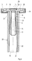
- a holding part 1 of the device according to the invention contains, for example, a circular, substantially plane-parallel plate 2, the rear side 3 of which is expediently flat for the purpose of contacting a wall, door or the like.
- an expandable part 5 protruding perpendicularly from the holding part 1 is fastened, which is designed like a sleeve and contains a plurality (here three) preferably identical segments 6, which preferably extend through parallel to a longitudinal axis 7 slots 8 spaced at equal angles are separated.
- the segments 6 have outer surfaces which lie on a cylinder surface and, in the exemplary embodiment, extend over a little less than a third of this cylinder surface.
- the front end of this ring 9 borders directly on the front side 4 of the plate 2, which at this point has a center hole 10 with a diameter corresponding to the inner diameter of the ring 9.
- the segments 6 are connected to the ring 9 in such a way that all the outer surfaces essentially form a common cylindrical outer surface 11, separated only by the slots 8, and their inner surfaces correspondingly form a common conical inner surface 12 with the longitudinal axis 7 as the axis.
- the diameter of the outer lateral surface 11 is slightly smaller than the diameter of a receiving opening in which the expandable part 5 is to be fastened.
- the inner conical lateral surface 12 has a diameter gradually decreasing from the rear end in the direction of the front end, the pitch angle ⁇ (FIG. 2) preferably being only a few degrees, for example 5 °.
- An essentially hollow cylindrical expansion part 15 of the device is shaped according to FIGS. 3 to 5 so that it can be at least partially inserted into the expandable part 5.
- the expansion part 15 is provided with an outer conical expansion surface 16 which has essentially the same slope as the inner conical lateral surface 12 of the expandable part 5 (angle of inclination ⁇ in FIG. 2) and a diameter which is from its rear end gradually decreases towards the front end.
- the smallest diameter is somewhat smaller than the largest diameter of the inner lateral surface 12 of the expandable part 5 and the size ratio is preferably chosen so that the spreading surface 16 of the expanding part 15 can be brought into contact with at least approximately half of the lateral surface 12 to a large area
- the expansion part 15 is also provided with a threaded section 17 which is continuous in the axial direction.
- Fig. 6 shows the device in the assembled state in a cylindrical receiving opening 19 of a component 20, which in the exemplary embodiment consists of a tubular element with a hollow cylindrical metal insert 21 and a hollow cylindrical plastic covering 22, which is also mounted thereon, both of which are coaxial with the longitudinal axis 7 of the expandable part 5 and are arranged coaxially to the longitudinal axes of a threaded bolt 23 and the expansion part 15.
- the threaded bolt 23 is assigned an element 24 which enables the expansion of the expandable part 15 in the component 20.
- the threaded bolt 23 consists of a normal countersunk screw, the head of which forms the element 24, can be arranged sunk in the correspondingly formed center hole 10 and e.g. has a receptacle 25 for an Allen key.
- the assembly is carried out by first pushing the expansion part 15 from the rear end into the expandable part 5, then loosely screwing the threaded bolt 23 from the rear 3 of the plate 2 through the central hole 10 and the ring 9 into the expansion part 15 and then the expandable part 5 is inserted into the receiving opening 19. Finally, the threaded bolt 23 is tightened by means of a tool attached to the element 24, as a result of which the expansion part 15 is drawn ever deeper into the expandable part 5 and its segments 6 are pressed radially outward against the cylindrical inner jacket of the metal insert 21. The tensile force exerted on the threaded bolt 23 is transmitted via the expansion surface 16 directly to the surface 12 of the expandable part 5 cooperating with it, so that high clamping forces can be achieved even on smooth surfaces.
- the element 24 acting as an abutment is supported on the plate 2 or also on an additional part located between it and the plate 2, ensures a fixed axial position of the threaded bolt 23 relative to the plate 2 during tensioning and thereby enables the tensioning. Without the element 24, the threaded bolt 23 would merely turn more and more into the expansion part 15 without being able to pull it against the part 5 to be expanded.
- the expandable part 5 and the spreading part 15 are simply rotated as a unit in the receiving opening 19 when the threaded bolt 23 is rotated.
- the expandable part 5 is expediently firmly connected to the plate 2, e.g. with this is made of plastic by injection molding in one piece.
- the plate 2 and with it the expandable part 5 can be held by hand during assembly until the spreading process is complete.
- the outer circumferential surface 11 of the expandable part 5 and / or the inner cylindrical circumferential surface of the metal insert 21 could also be roughened sufficiently to prevent the expandable part 5 from rotating at least when it is already somewhat pretensioned by the spreading part 15. So that the component is correctly centered on the holding part 1, this preferably has an annular groove 27 on its front side 4, into which the front end of the component 20 is inserted during assembly.
- the device is provided with a means which prevents such rotations.
- This means consists, for example, of an axially effective tongue and groove connection, by means of which the expansion part is rotatably mounted in the expandable part and which consists, for example, of one of the slots 8 (FIG. 1) and a lateral, radially projecting and into this slot 8 projecting, on the expansion part 15 attached web 28 (Fig. 3 to 5) is formed.
- This web 28 can be made, for example, with the expansion part 15 in one piece, but can also be retrofitted. The effect of the ring and the tongue and groove connection is corresponding when the device is to be dismantled again. 5, three such webs 28 can also be provided, each of which protrude into one of the three slots.
- the component 20 can be shortened in a simple manner.
- the bolt 23 is slightly unscrewed, the element 24 lifting off slightly from the plate 2, and then a stroke in the axial direction of the threaded bolt 23, as a result of which the expansion part 15 in the expandable part 5 is axially displaced until the element 24 is open again the plate 2 rests.
- the bracing is released and the entire device can now be pulled out of the receiving opening 19.
- the component 20 is then shortened somewhat at its front end, as indicated in FIG. 6A, and the device is then reinserted. Since it then assumes the same relative position to the front end of the component 20, the same static conditions also result.
- the prerequisite is, of course, that the receiving opening 19 is long enough to be able to accommodate the parts 5.15 even after shortening.
- the component 20 can also be easily extended.
- a short, tubular component 31, also consisting of a metal insert and a plastic jacket, is placed coaxially on the front end of component 20 and the device is then inserted and fastened in the manner described.
- a front section of the expandable part 5 comes to rest in the component 31, so that the part 5 simultaneously acts as a centering element.
- the axial length of the expandable part 5 is therefore preferably as large, e.g. at least approx. 40 mm, so that a part of this length can be used for any necessary extensions, without the mechanical stability substantially decreasing due to the shorter section of part 5 remaining in component 20.
- the plate 2, the expandable part 5, the threaded bolt 23 and the expansion part 15 are preferably made of steel. This ensures that the Devices in combination with the metal inserts 21 form a skeleton that is preserved even in the event of a fire.
- the segments 6 are preferably at their front ends with the help of deformable parts 33 connected to the ring 9.
- deformable parts 33 preferably consist of thin connecting webs or wall sections which result from the fact that between the ring 9 and the outer circumferential surface 11 formed by the segments 6, a groove 34 or groove, indicated only by dashed lines, is formed in FIG. 2 by turning or milling that reaches up to the inner surface 12. 6 is generated by tightening the threaded bolt 23, a radial pressure, then the segments 6 can be pressed practically over their entire length against the cylindrical inner wall of the metal insert 21 by bending the bendable parts 33, so that due to the large-area contact and the associated large surface pressure, the desired large frictional force is generated even if the interacting surfaces are smooth.
- the parts mentioned can also be made of plastic, in particular by injection molding, in which case the grooves 34 are generally not necessary because of the mostly greater flexibility of the plastic material or the segments 6 can be molded onto the ring 9 in such a way that the desired effect results.
- the holding part 1 can be fastened in a conventional manner to a wall or the like, on which it is placed with its rear side 3.
- the plate 2 has the usual screw holes 35 on its circumference surrounding the center hole 10.
- the plate 2 which preferably only forms the lower part of a two-part rosette, can be covered in a known manner with a cover cap 36 which is fitted onto the component 20.
- the ring 9 acts as Centering piece and the annular groove 27 as a support for the component 20.
- This has the advantage that this function is retained even after the component 20 has been shortened or lengthened. This means that no additional centering piece is required when extending.
- this arrangement also does not require a section of the metal insert 21 projecting from the plastic casing 22 as a centering piece, there is the further essential advantage that the metal insert 21 and the plastic casing 22 have the same axial length and can be arranged together in the annular groove 27. This makes it possible to shorten the components 20 without first separating the plastic casing 22 from the metal inserts 21 or to lengthen them according to FIG. 6B by means of simple intermediate pieces.
- the expansion part 15 When unscrewing the connection shown in FIG. 6, the expansion part 15 could come loose from the threaded bolt 23 under unfavorable circumstances. This alone or also an additional impact which is inadvertently exerted on the threaded bolt 23 could then result in the expansion part 15 falling down in the component 20. Is its other end e.g. firmly connected to other components, the expansion part 15 would be lost or, if necessary, could be obtained again by dismantling the other components. Such a loosening of the expansion part 15 is preferably prevented in a further embodiment of the invention in that it is captively connected to the expandable part 5, e.g.
- one of the slots 8 is closed at its rear end or at least one segment is provided at its rear end with a bend which projects radially towards them, thereby preventing the expansion part 15 in the component 20 from falling down, at least in the assembled state.
- the segments 6 involved are to be made sufficiently elastic so that the joining of the device is not impeded.
- the embodiment according to FIG. 7 differs from the embodiment according to FIGS. 1 to 6 in that a threaded bolt 39 and an expansion part 40 can be firmly connected to one another or are firmly connected to one another and, for example, are made from one piece.
- the bolt 39 has one External thread section, the free end 41 is as flush as possible with the back 3 of the plate 2.
- An element 42 is screwed onto this end, which, in contrast to element 24, consists of a nut which has an internal thread and, for example, a hexagonal external cross section and, in the assembled state, is supported on the bottom 43 of an extension 44 of the central hole in plate 2 and in this extension 44 preferably sunk, but is arranged so that it can be easily operated with an appropriate tool.
- the device according to FIG. 7 can be designed like the device according to FIGS. 1 to 6, which is why the same reference numerals are used for the same parts.
- the device according to FIG. 7 is fastened by first inserting the expandable part 5 into the receiving opening 19 until the component 20 rests on the bottom of the annular groove 27, and then the element 42 on the Threaded bolt 39 is tightened.
- the element 42 allows the expandable part 5 to be braced, since when it is rotated in the tightening direction it initially lies against the plate 2 or the like, thereby acting as an abutment with a fixed axial position relative to the plate 2 and, when the part is rotated further, pulls into the expandable part 5.
- the holding part 1 can then be attached to a wall or the like.
- the element 42 and the element 24 serve the purpose of attaching a tool and thereby producing the bracing.
- a holding part 51 of the device according to the invention contains, for example, a circular, essentially plane-parallel plate 52, the rear side 53 of which is expediently flat for the purpose of contacting a wall, door or the like.
- an expandable part 55 which projects vertically from the holding part 51 and is designed like a sleeve and contains a plurality (here four) preferably identical segments 56.
- these segments 56 are not separated by slots running exactly parallel to a longitudinal axis 57, but by slots 58, which extend in the longitudinal direction of the expandable part 55, but are wedge-shaped.
- the slots 58 have in longitudinal section approximately the shape of an isosceles triangle, the base of which is located at the rear end 59 of the part 55 and the two legs of the side surfaces 60 (FIG. 9) which run obliquely to the longitudinal axis 57 of FIG Segments 56 are formed.
- a wedge angle ⁇ (FIG. 10) is preferably only a few degrees, for example 5 °.
- the segments 56 also have outer lateral surfaces 61, which lie on a cylindrical surface, and inner surfaces 62, which, in contrast to FIGS. 1 to 7, are also essentially arranged on a cylindrical surface and, like the outer lateral surfaces 61, each have a little less than a quarter extend this cylinder surface.
- the front ends of the segments 56 are connected to the plate 52, which has a center hole 63, the smallest inside diameter of which corresponds approximately to that of the inner lateral surface 62.
- the device according to FIGS. 11 and 12 has an essentially hollow cylindrical expansion part 66 which is shaped such that it can be at least partially inserted into the expandable part 55.
- the expansion part 66 is provided with radially protruding, wedge-shaped projections 67 where the expandable part 55 has the slots 58, the side surfaces of which act as expansion surfaces 68 and the shape of which is adapted to the side surfaces 60 of the expandable part 55 are.
- These lugs 67 like the slots 58, gradually become narrower from the rear end 69 of the expansion part 66 in the direction of its front end (FIG.
- the dimensions of the expansion surfaces 68 expediently corresponding to those of the side surfaces 60 of the slots 58, so that a large-area interaction occurs when Spreading results.
- the width of the lugs 67 at the front end of the expansion part 66 is preferably so much smaller than the slot width at the rear end 59 of the expandable part 55 that the expansion parts 66 according to FIG. 13 from behind in the expandable parts 55 and correspondingly the lugs 67 from pushed forward so far in the slots 58 can be until the lugs 67 are at least about half in the slots 58 and can exert a high radial force on the expandable part 55.
- the expansion part 66 is also provided with an internal thread section 70 which is continuous in the axial direction and into which the threaded bolt 23 of the exemplary embodiment according to FIGS. 1 to 6 can be screwed.
- FIG. 13 shows the device in the assembled state in the cylindrical receiving opening 19 of the component 20, which is designed in accordance with FIGS. 6 and 7.
- the assembly also takes place in this embodiment in that first the expansion part 66 is pushed from the rear end into the expandable part 55, then the threaded bolt 23 is loosely screwed from the front through the center hole 63 of the plate 52 into the expansion part 66 and then the expandable part Part 55 is inserted into the receiving opening 19. Finally, the threaded bolt 23 is tightened by means of a tool attached to the element 24, as a result of which the expansion part 66 is drawn ever deeper into the expandable part 55.
- the spreading surfaces 68 lie against the side surfaces 60 of the segments 56 facing them and thereby push them apart more and more in the circumferential direction and consequently radially outwards against the cylindrical inner jacket of the metal insert 21.
- the expandable part 55 can do so all the more Surface pressure in the receiving opening 19 are clamped, the greater the number of slots 58 and lugs 67 or the interacting surfaces 60, 68.
- the holding part 52 can be fastened to a wall or the like by means of screw holes 71.
- the device according to FIGS. 8 to 13 can be manufactured and used in all variants which are described and claimed above and below for the device according to FIGS. 1 to 7. This applies in particular to the variant explained with reference to FIG. 7.
- the invention is not restricted to the exemplary embodiments described, which can be modified in many ways.
- the element 24 does not need to consist of one piece with the threaded bolt 23, but can also be subsequently fitted onto it and attached to it.
- the expandable part can have more or less than the illustrated axial slots 8 or 58.
- the use of two segments consisting of half shells is particularly suitable.
- the device is also suitable for fastening components other than tubular, namely in particular, for example, curved, cross-shaped or T-shaped node elements with appropriately designed receiving openings.
- the shapes of the inner cross sections of the recesses and the outer cross sections of the expandable parts at least partially differently, that is to say, for example, to provide expandable parts which interact with cylindrical recesses and whose outer cross sections are hexagonal or octagonal.
- the corresponding diameters or cross sections need only correspond essentially. The degree of agreement will mainly be determined by the forces to be transmitted or the stability of the connection to be achieved and the materials used in the individual case.
Landscapes
- Health & Medical Sciences (AREA)
- Public Health (AREA)
- Engineering & Computer Science (AREA)
- General Engineering & Computer Science (AREA)
- Epidemiology (AREA)
- General Health & Medical Sciences (AREA)
- Mechanical Engineering (AREA)
- Dowels (AREA)
- Connection Of Plates (AREA)
- Clamps And Clips (AREA)
Claims (20)
- Dispositif de fixation d'un composant (20), tubulaire notamment, doté d'une ouverture de réception (19), sur une paroi ou autres, composé d'un élément de fixation (1, 51) présentant un trou (10, 63), d'un élément extensible (5, 55), destiné à l'introduction dans l'ouverture de réception et présentant un passage, et d'un boulonnage, destiné à l'écartement de l'élément extensible et à l'assemblage de l'élément de fixation avec le composant, caractérisé en ce que l'élément extensible (5, 55) présente au moins deux segments (6, 56), séparés par une fente (8, 58), au moins, prévue dans le sens longitudinal de l'élément extensible (5, 55), et en ce qu'un élément d'écartement (15, 40, 66) est prévu, cet élément pouvant être introduit, en partie du moins, dans le passage, et présentant une surface d'écartement (16, 68), au moins, qui concourt sur une grande portée avec une surface (12, 60), qui lui est adaptée, de l'élément extensible (5, 55).
- Dispositif suivant la revendication 1, caractérisé en ce que l'élément de fixation (1, 51) est muni d'un trou (10, 63), et en ce que le boulonnage présente un boulon fileté (23, 39), destiné au serrage radial de l'élément extensible (5, 55) dans l'ouverture de réception (19), et pénétrant dans le trou (10, 63) et dans le passage, ainsi qu'un élément (24, 42), associé au boulon fileté et permettant le serrage.
- Dispositif suivant l'une des revendications 1 et 2, caractérisé en ce que, à l'état de montage, l'élément extensible (5, 55), l'élément d'écartement (15, 40, 66), et le boulon fileté (23, 39), sont essentiellement disposés sur la face avant (4, 54), et l'élément (10, 42) sur la face arrière (3, 53) de l'élément de fixation (1, 51).
- Dispositif suivant l'une quelconque des revendications 1 à 3, caractérisé en ce que le boulon fileté (23) peut être fixé dans une section taraudée (17, 70) de l'élément d'écartement (15, 66), et en ce que l'élément (24) se compose d'un embout radial, fixé rigidement sur le boulon fileté (23).
- Dispositif suivant la revendication 4, caractérisé en ce que l'élément (24) est réalisé sous forme de tête fraisée.
- Dispositif suivant l'une quelconque des revendications 1 à 3, caractérisé en ce que le boulon fileté (39) est fixé rigidement sur l'élément d'écartement (40), et en ce que l'élément (42) est un écrou, qui peut être vissé, ou est vissé, sur le boulon fileté (39).
- Dispositif suivant l'une quelconque des revendications 1 à 6, caractérisé par un assemblage fixe de l'élément de fixation (1, 51) et de l'élément extensible (5, 55).
- Dispositif suivant l'une quelconque des revendications 1 à 5, caractérisé en ce qu'il présente un moyen, s'opposant à une rotation de l'élément d'écartement (15, 66) dans l'élément extensible (5, 55).
- Dispositif suivant la revendication 8, caractérisé en ce que le moyen est réalisé à la manière d'un assemblage à rainure et languette.
- Dispositif suivant la revendication 9, caractérisé en ce que le moyen est au moins formé par l'une des fentes (8), et par un profil radial (28), prévu sur l'élément d'écartement (15).
- Dispositif suivant la revendication 9, caractérisé en ce que le moyen est au moins formé par l'une des fentes (58) et par l'un des embouts (67).
- Dispositif suivant l'une des revendications 10 et 11, caractérisé en ce que la fente (8, 58) est fermée sur l'extrémité arrière, ou en ce que l'un des segments (6, 56), du moins, est muni d'un cintrage sur l'extrémité arrière.
- Dispositif suivant l'une quelconque des revendications 1 à 12, caractérisé en ce que l'élément extensible (5, 55) se compose de deux ou de plusieurs coques, séparées les unes des autres.
- Dispositif suivant l'une quelconque des revendications 1 à 13, caractérisé en ce que l'élément extensible (5) se compose de deux segments (6), au moins, séparés par une fente (8) parallèle à l'axe, au moins, et formant conjointement la surface d'enveloppe intérieure (12) conique, et en ce que l'élément d'écartement (15, 40) présente une surface d'écartement externe (16), concourant avec la surface d'enveloppe intérieure (12).
- Dispositif suivant l'une quelconque des revendications 1 à 13, caractérisé en ce que l'élément extensible (55) se compose de deux segments (56), au moins, séparés par une fente (58), au moins, cunéiforme et limitée par des surfaces latérales (60), et qui forment une surface d'enveloppe externe (61) essentiellement cylindrique, et en ce que l'élément d'écartement (66) présente un embout (67), au moins, pouvant être introduit dans la fente (58), avec des surfaces d'écartement latérales (68), qui concourent avec les surfaces latérales (60).
- Dispositif suivant l'une des revendications 14 et 15, caractérisé en ce que les segments (6, 56) sont maintenus par une bague (9), réalisée sur l'extrémité avant de l'élément extensible (5, 55).
- Dispositif suivant la revendication 16, caractérisé en ce que la bague (9) est réalisée sous forme de pièce de centrage pour le composant (20).
- Dispositif suivant l'une quelconque des revendications 1 à 17, caractérisé en ce que l'élément extensible (5, 55) est en acier.
- Dispositif suivant l'une quelconque des revendications 1 à 18, caractérisé en ce que les segments (5, 55) sont assemblés avec la bague (9), sur leurs extrémités avant, au moyen d'éléments déformables (33).
- Dispositif suivant la revendication 19, caractérisé en ce que les éléments déformables (33) se composent de minces profils de jonction ou d'éléments de parois.
Priority Applications (1)
| Application Number | Priority Date | Filing Date | Title |
|---|---|---|---|
| AT9191115684T ATE105379T1 (de) | 1990-09-27 | 1991-09-16 | Vorrichtung zur befestigung eines insbesondere rohrfoermigen bauteils an einer wand oder dergleichen. |
Applications Claiming Priority (2)
| Application Number | Priority Date | Filing Date | Title |
|---|---|---|---|
| DD90344254A DD299202A5 (de) | 1990-09-27 | 1990-09-27 | Vorrichtung zur befestigung eines insbesondere rohrfoermigen bauteils an einer wand oder dgl. |
| DD344254 | 1990-09-27 |
Publications (2)
| Publication Number | Publication Date |
|---|---|
| EP0477713A1 EP0477713A1 (fr) | 1992-04-01 |
| EP0477713B1 true EP0477713B1 (fr) | 1994-05-04 |
Family
ID=5620549
Family Applications (1)
| Application Number | Title | Priority Date | Filing Date |
|---|---|---|---|
| EP91115684A Expired - Lifetime EP0477713B1 (fr) | 1990-09-27 | 1991-09-16 | Dispositif pour fixer notamment une pièce de construction tubulaire à une paroi ou un élément similaire |
Country Status (4)
| Country | Link |
|---|---|
| EP (1) | EP0477713B1 (fr) |
| AT (1) | ATE105379T1 (fr) |
| DD (1) | DD299202A5 (fr) |
| DE (2) | DE9013681U1 (fr) |
Cited By (1)
| Publication number | Priority date | Publication date | Assignee | Title |
|---|---|---|---|---|
| EP1092881A2 (fr) | 1999-10-15 | 2001-04-18 | Hewi Heinrich Wilke Gmbh | Dispositif de fixation ou d'assemblage d'éléments de construction |
Families Citing this family (16)
| Publication number | Priority date | Publication date | Assignee | Title |
|---|---|---|---|---|
| DE4223563C1 (en) * | 1992-07-17 | 1993-09-02 | Mercedes-Benz Aktiengesellschaft, 70327 Stuttgart, De | Cover for tubular component - has protrusion extending into component and containing boss expanding it into engaged position |
| DE4422211C1 (de) * | 1994-06-24 | 1995-11-30 | Happich Gmbh Gebr | Bausatz, insbesondere für Busse |
| DE19522224C2 (de) * | 1994-06-24 | 1998-07-02 | Happich Fahrzeug & Ind Teile | Bausatz, insbesondere für Busse |
| EP0688919B1 (fr) | 1994-06-24 | 1998-04-22 | HAPPICH Fahrzeug- und Industrieteile GmbH | Assemblage de construction, notamment pour les autobus |
| GB2315989B (en) * | 1995-06-02 | 1999-01-13 | Bellmar Limited | A curtain hanger system |
| FR2744353B1 (fr) * | 1996-02-01 | 1998-04-30 | Cessot Decoration Sarl | Embout pour tringle a rideaux |
| DE29803781U1 (de) * | 1998-03-05 | 1999-07-08 | HEWI Heinrich Wilke GmbH, 34454 Bad Arolsen | Gebrauchsgegenstand, insbesondere Beschlag- oder Ausstattungsteil |
| DE29922221U1 (de) * | 1999-12-18 | 2000-03-16 | Erwin Müller GmbH & Co, 49808 Lingen | Wandhalterung zur Anbringung von Sanitärarmaturen |
| DE10021825B4 (de) * | 2000-05-04 | 2012-08-30 | Hewi Heinrich Wilke Gmbh | Verbindungseinrichtungen und Bausystem |
| DE20012779U1 (de) * | 2000-07-21 | 2001-11-29 | DE-STA-CO Metallerzeugnisse GmbH, 61449 Steinbach | Verbindungselement |
| WO2003048589A1 (fr) * | 2001-12-04 | 2003-06-12 | Visplay International Ag | Connecteur concu pour monter des meubles modulaires |
| WO2009042233A1 (fr) * | 2007-09-28 | 2009-04-02 | Colleen O' Connell | Systèmes permettant de déplacer des barres de douche |
| GB2501453B (en) * | 2010-12-02 | 2016-08-03 | Croydex Ltd | Mounting for a shower curtain rod |
| DE102015122444A1 (de) | 2015-12-21 | 2017-06-22 | Bombardier Transportation Gmbh | Haltestangensystem |
| CN105840607A (zh) * | 2016-04-28 | 2016-08-10 | 苏州市林氏精密五金标准件制造有限公司 | 一种异形套筒连接件 |
| DE102021127160A1 (de) | 2021-10-20 | 2023-04-20 | Bayerische Motoren Werke Aktiengesellschaft | Distanzhülse |
Family Cites Families (4)
| Publication number | Priority date | Publication date | Assignee | Title |
|---|---|---|---|---|
| US2904379A (en) * | 1958-05-22 | 1959-09-15 | Rada Products Company | Hollow support structures having hidden connecting means |
| DE2460382C2 (de) * | 1974-12-20 | 1986-04-17 | Rudolf Dipl.-Wirtsch.-Ing. 3548 Arolsen Wilke | Bausatz mit wenigstens einem Knotenelement |
| DE3132855A1 (de) * | 1981-08-20 | 1983-03-03 | Rudolf Dipl.-Wirtsch.-Ing. 3548 Arolsen Wilke | Rosetten-unterteil |
| CH675897A5 (en) * | 1988-11-21 | 1990-11-15 | Karl Breschan | Component connector to pipe end - has screw pulling wedge-shaped body into clamping one inside pipe |
-
1990
- 1990-09-27 DD DD90344254A patent/DD299202A5/de not_active IP Right Cessation
- 1990-10-01 DE DE9013681U patent/DE9013681U1/de not_active Expired - Lifetime
-
1991
- 1991-09-16 DE DE59101567T patent/DE59101567D1/de not_active Expired - Fee Related
- 1991-09-16 EP EP91115684A patent/EP0477713B1/fr not_active Expired - Lifetime
- 1991-09-16 AT AT9191115684T patent/ATE105379T1/de active
Cited By (1)
| Publication number | Priority date | Publication date | Assignee | Title |
|---|---|---|---|---|
| EP1092881A2 (fr) | 1999-10-15 | 2001-04-18 | Hewi Heinrich Wilke Gmbh | Dispositif de fixation ou d'assemblage d'éléments de construction |
Also Published As
| Publication number | Publication date |
|---|---|
| DD299202A5 (de) | 1992-04-02 |
| DE9013681U1 (de) | 1991-02-14 |
| EP0477713A1 (fr) | 1992-04-01 |
| ATE105379T1 (de) | 1994-05-15 |
| DE59101567D1 (de) | 1994-06-09 |
Similar Documents
| Publication | Publication Date | Title |
|---|---|---|
| EP0477713B1 (fr) | Dispositif pour fixer notamment une pièce de construction tubulaire à une paroi ou un élément similaire | |
| DE4030978C2 (de) | Verbindungseinrichtung für Rohre | |
| EP0413235A2 (fr) | Noeud d'assemblage | |
| EP0206327B1 (fr) | Dispositif de connexion d'éléments tubulaires | |
| DE69608951T2 (de) | Blindniet und blindnietverfahren | |
| EP0008085B1 (fr) | Cheville | |
| EP0477707B1 (fr) | Dispositif d'assemblage notamment pour d'une pièce de construction tubulaire | |
| DE4210488A1 (de) | Verbindungseinrichtung für ein insbesondere rohrförmiges Bauteil | |
| EP0564889A1 (fr) | Dispositif de raccordement, notamment pour une pièce de construction tubulaire | |
| EP2627915B1 (fr) | Dispositif d'ancrage destiné à fixer une pièce sur un élément de support | |
| DE2655728C2 (de) | Lösbare Naben-Wellenverbindung | |
| EP0475216B1 (fr) | Dispositif d'assemblage entre des poutres et des noeuds d'une structure tridimensionelle | |
| EP1092881A2 (fr) | Dispositif de fixation ou d'assemblage d'éléments de construction | |
| DE19912068B4 (de) | Wellen- oder Stellmutter und Verfahren zu ihrer Herstellung | |
| DE10134960A1 (de) | Befestigungselement | |
| DE3910644C2 (fr) | ||
| DE4010082C2 (de) | Dübel, insbesondere Heizkörperdübel | |
| DE3328232C2 (de) | Raumfachwerk | |
| DE29505791U1 (de) | Befestigungselement zum lösbaren Verbinden eines Mehrkantrohres | |
| DE20302751U1 (de) | Profilverbindungseinrichtung | |
| DE202016001304U1 (de) | Verbindungselement für Bauteile eines Katzenkratzbaums und Katzenkratzbaum mit einem solchen Verbindungselement | |
| DE2219788A1 (de) | Treppenfoermige tragkonstruktion fuer gerade und/oder gewendelte treppenlaeufe | |
| DE1575971C3 (de) | Kupplung zur Befestigung einer Nabe auf einer Welle durch eine konische Klemm hülse | |
| DE2734520C3 (de) | Schalungszuganker aus Kunststoff | |
| DE10252233A1 (de) | In seinem Durchmesser veränderbarer Passstift, mit welchen zwei Teile zueinander zentriergenau festgelegt werden können |
Legal Events
| Date | Code | Title | Description |
|---|---|---|---|
| PUAI | Public reference made under article 153(3) epc to a published international application that has entered the european phase |
Free format text: ORIGINAL CODE: 0009012 |
|
| AK | Designated contracting states |
Kind code of ref document: A1 Designated state(s): AT BE CH DE FR GB IT LI LU NL |
|
| RIN1 | Information on inventor provided before grant (corrected) |
Inventor name: JAEGER, HORST Inventor name: WULFERT, KARL-LUDWIG Inventor name: DZIUK, RICHARD |
|
| 17P | Request for examination filed |
Effective date: 19920902 |
|
| 17Q | First examination report despatched |
Effective date: 19930916 |
|
| GRAA | (expected) grant |
Free format text: ORIGINAL CODE: 0009210 |
|
| AK | Designated contracting states |
Kind code of ref document: B1 Designated state(s): AT BE CH DE FR GB IT LI LU NL |
|
| REF | Corresponds to: |
Ref document number: 105379 Country of ref document: AT Date of ref document: 19940515 Kind code of ref document: T |
|
| REF | Corresponds to: |
Ref document number: 59101567 Country of ref document: DE Date of ref document: 19940609 |
|
| GBT | Gb: translation of ep patent filed (gb section 77(6)(a)/1977) |
Effective date: 19940523 |
|
| ET | Fr: translation filed | ||
| ITF | It: translation for a ep patent filed | ||
| PG25 | Lapsed in a contracting state [announced via postgrant information from national office to epo] |
Ref country code: LU Free format text: LAPSE BECAUSE OF NON-PAYMENT OF DUE FEES Effective date: 19940930 |
|
| PLBE | No opposition filed within time limit |
Free format text: ORIGINAL CODE: 0009261 |
|
| STAA | Information on the status of an ep patent application or granted ep patent |
Free format text: STATUS: NO OPPOSITION FILED WITHIN TIME LIMIT |
|
| 26N | No opposition filed | ||
| PGFP | Annual fee paid to national office [announced via postgrant information from national office to epo] |
Ref country code: CH Payment date: 20000809 Year of fee payment: 10 |
|
| PGFP | Annual fee paid to national office [announced via postgrant information from national office to epo] |
Ref country code: FR Payment date: 20000821 Year of fee payment: 10 |
|
| PGFP | Annual fee paid to national office [announced via postgrant information from national office to epo] |
Ref country code: BE Payment date: 20000904 Year of fee payment: 10 |
|
| PGFP | Annual fee paid to national office [announced via postgrant information from national office to epo] |
Ref country code: GB Payment date: 20000913 Year of fee payment: 10 |
|
| PGFP | Annual fee paid to national office [announced via postgrant information from national office to epo] |
Ref country code: AT Payment date: 20000925 Year of fee payment: 10 |
|
| PGFP | Annual fee paid to national office [announced via postgrant information from national office to epo] |
Ref country code: NL Payment date: 20000930 Year of fee payment: 10 |
|
| PGFP | Annual fee paid to national office [announced via postgrant information from national office to epo] |
Ref country code: DE Payment date: 20001125 Year of fee payment: 10 |
|
| PG25 | Lapsed in a contracting state [announced via postgrant information from national office to epo] |
Ref country code: GB Free format text: LAPSE BECAUSE OF NON-PAYMENT OF DUE FEES Effective date: 20010916 Ref country code: AT Free format text: LAPSE BECAUSE OF NON-PAYMENT OF DUE FEES Effective date: 20010916 |
|
| PG25 | Lapsed in a contracting state [announced via postgrant information from national office to epo] |
Ref country code: LI Free format text: LAPSE BECAUSE OF NON-PAYMENT OF DUE FEES Effective date: 20010930 Ref country code: CH Free format text: LAPSE BECAUSE OF NON-PAYMENT OF DUE FEES Effective date: 20010930 Ref country code: BE Free format text: LAPSE BECAUSE OF NON-PAYMENT OF DUE FEES Effective date: 20010930 |
|
| REG | Reference to a national code |
Ref country code: GB Ref legal event code: IF02 |
|
| BERE | Be: lapsed |
Owner name: HEINRICH WILKE G.M.B.H. HEWI Effective date: 20010930 |
|
| PG25 | Lapsed in a contracting state [announced via postgrant information from national office to epo] |
Ref country code: NL Free format text: LAPSE BECAUSE OF NON-PAYMENT OF DUE FEES Effective date: 20020401 |
|
| PG25 | Lapsed in a contracting state [announced via postgrant information from national office to epo] |
Ref country code: DE Free format text: LAPSE BECAUSE OF NON-PAYMENT OF DUE FEES Effective date: 20020501 |
|
| GBPC | Gb: european patent ceased through non-payment of renewal fee |
Effective date: 20010916 |
|
| REG | Reference to a national code |
Ref country code: CH Ref legal event code: PL |
|
| PG25 | Lapsed in a contracting state [announced via postgrant information from national office to epo] |
Ref country code: FR Free format text: LAPSE BECAUSE OF NON-PAYMENT OF DUE FEES Effective date: 20020531 |
|
| NLV4 | Nl: lapsed or anulled due to non-payment of the annual fee |
Effective date: 20020401 |
|
| REG | Reference to a national code |
Ref country code: FR Ref legal event code: ST |
|
| NLV4 | Nl: lapsed or anulled due to non-payment of the annual fee |
Effective date: 20020401 |
|
| PG25 | Lapsed in a contracting state [announced via postgrant information from national office to epo] |
Ref country code: IT Free format text: LAPSE BECAUSE OF NON-PAYMENT OF DUE FEES Effective date: 20050916 |