EP1092881A2 - Dispositif de fixation ou d'assemblage d'éléments de construction - Google Patents
Dispositif de fixation ou d'assemblage d'éléments de construction Download PDFInfo
- Publication number
- EP1092881A2 EP1092881A2 EP00122516A EP00122516A EP1092881A2 EP 1092881 A2 EP1092881 A2 EP 1092881A2 EP 00122516 A EP00122516 A EP 00122516A EP 00122516 A EP00122516 A EP 00122516A EP 1092881 A2 EP1092881 A2 EP 1092881A2
- Authority
- EP
- European Patent Office
- Prior art keywords
- sleeve
- receiving opening
- thread part
- threaded bolt
- internal thread
- Prior art date
- Legal status (The legal status is an assumption and is not a legal conclusion. Google has not performed a legal analysis and makes no representation as to the accuracy of the status listed.)
- Withdrawn
Links
- 238000005304 joining Methods 0.000 claims description 7
- 238000003780 insertion Methods 0.000 claims description 6
- 230000037431 insertion Effects 0.000 claims description 6
- 235000019738 Limestone Nutrition 0.000 claims 1
- 239000006028 limestone Substances 0.000 claims 1
- 229910000760 Hardened steel Inorganic materials 0.000 description 6
- 238000004519 manufacturing process Methods 0.000 description 6
- 239000000463 material Substances 0.000 description 5
- 241000209035 Ilex Species 0.000 description 4
- 238000004026 adhesive bonding Methods 0.000 description 2
- 239000002184 metal Substances 0.000 description 2
- 208000000260 Warts Diseases 0.000 description 1
- 239000002390 adhesive tape Substances 0.000 description 1
- 238000010276 construction Methods 0.000 description 1
- 230000008878 coupling Effects 0.000 description 1
- 238000010168 coupling process Methods 0.000 description 1
- 238000005859 coupling reaction Methods 0.000 description 1
- 230000007812 deficiency Effects 0.000 description 1
- 230000000694 effects Effects 0.000 description 1
- 238000007373 indentation Methods 0.000 description 1
- 238000001746 injection moulding Methods 0.000 description 1
- 238000000034 method Methods 0.000 description 1
- 238000007493 shaping process Methods 0.000 description 1
- 201000010153 skin papilloma Diseases 0.000 description 1
- 210000002105 tongue Anatomy 0.000 description 1
Images


Classifications
-
- F—MECHANICAL ENGINEERING; LIGHTING; HEATING; WEAPONS; BLASTING
- F16—ENGINEERING ELEMENTS AND UNITS; GENERAL MEASURES FOR PRODUCING AND MAINTAINING EFFECTIVE FUNCTIONING OF MACHINES OR INSTALLATIONS; THERMAL INSULATION IN GENERAL
- F16B—DEVICES FOR FASTENING OR SECURING CONSTRUCTIONAL ELEMENTS OR MACHINE PARTS TOGETHER, e.g. NAILS, BOLTS, CIRCLIPS, CLAMPS, CLIPS OR WEDGES; JOINTS OR JOINTING
- F16B21/00—Means for preventing relative axial movement of a pin, spigot, shaft or the like and a member surrounding it; Stud-and-socket releasable fastenings
- F16B21/10—Means for preventing relative axial movement of a pin, spigot, shaft or the like and a member surrounding it; Stud-and-socket releasable fastenings by separate parts
-
- F—MECHANICAL ENGINEERING; LIGHTING; HEATING; WEAPONS; BLASTING
- F16—ENGINEERING ELEMENTS AND UNITS; GENERAL MEASURES FOR PRODUCING AND MAINTAINING EFFECTIVE FUNCTIONING OF MACHINES OR INSTALLATIONS; THERMAL INSULATION IN GENERAL
- F16B—DEVICES FOR FASTENING OR SECURING CONSTRUCTIONAL ELEMENTS OR MACHINE PARTS TOGETHER, e.g. NAILS, BOLTS, CIRCLIPS, CLAMPS, CLIPS OR WEDGES; JOINTS OR JOINTING
- F16B2/00—Friction-grip releasable fastenings
- F16B2/20—Clips, i.e. with gripping action effected solely by the inherent resistance to deformation of the material of the fastening
- F16B2/22—Clips, i.e. with gripping action effected solely by the inherent resistance to deformation of the material of the fastening of resilient material, e.g. rubbery material
- F16B2/24—Clips, i.e. with gripping action effected solely by the inherent resistance to deformation of the material of the fastening of resilient material, e.g. rubbery material of metal
- F16B2/241—Clips, i.e. with gripping action effected solely by the inherent resistance to deformation of the material of the fastening of resilient material, e.g. rubbery material of metal of sheet metal
- F16B2/245—Clips, i.e. with gripping action effected solely by the inherent resistance to deformation of the material of the fastening of resilient material, e.g. rubbery material of metal of sheet metal external, i.e. with contracting action
- F16B2/246—Clips, i.e. with gripping action effected solely by the inherent resistance to deformation of the material of the fastening of resilient material, e.g. rubbery material of metal of sheet metal external, i.e. with contracting action the clip being released by tilting the clip or a part thereof to a position in which the axis of the openings surrounding the gripped elements is parallel to, or coincides with, the axis of the gripped elements
-
- F—MECHANICAL ENGINEERING; LIGHTING; HEATING; WEAPONS; BLASTING
- F16—ENGINEERING ELEMENTS AND UNITS; GENERAL MEASURES FOR PRODUCING AND MAINTAINING EFFECTIVE FUNCTIONING OF MACHINES OR INSTALLATIONS; THERMAL INSULATION IN GENERAL
- F16B—DEVICES FOR FASTENING OR SECURING CONSTRUCTIONAL ELEMENTS OR MACHINE PARTS TOGETHER, e.g. NAILS, BOLTS, CIRCLIPS, CLAMPS, CLIPS OR WEDGES; JOINTS OR JOINTING
- F16B21/00—Means for preventing relative axial movement of a pin, spigot, shaft or the like and a member surrounding it; Stud-and-socket releasable fastenings
- F16B21/10—Means for preventing relative axial movement of a pin, spigot, shaft or the like and a member surrounding it; Stud-and-socket releasable fastenings by separate parts
- F16B21/16—Means for preventing relative axial movement of a pin, spigot, shaft or the like and a member surrounding it; Stud-and-socket releasable fastenings by separate parts with grooves or notches in the pin or shaft
- F16B21/18—Means for preventing relative axial movement of a pin, spigot, shaft or the like and a member surrounding it; Stud-and-socket releasable fastenings by separate parts with grooves or notches in the pin or shaft with circlips or like resilient retaining devices, i.e. resilient in the plane of the ring or the like; Details
Definitions
- the invention relates to a device in the preambles of claims 1 and 17 specified genus.
- Devices of this type are known in numerous embodiments. They serve before all to connect the components of modular pipe or rod and Existing pipe or rod systems. From the elements of the Modules can e.g. Decorative or furniture frames, trade fair and exhibition stands, Frames, swing door handles, handle bars, furniture, railings or handrails and numerous other structures are put together. Alternatively, the devices but can also be used to connect other components, provided that they have receiving openings have provided connection ends.
- pipe connectors in the form of sleeves are known, both inside and outside with radially protruding, barb-like punched out of the outer surface of the sleeve Locking tongues are provided (DE 74 17 689 U1).
- sleeves are used to make plug connections between two pipes and do not offer any Possibility of abutting the two pipes to be connected with hair-thin butt joints to let or axially brace in the area of the joint, as in the above mentioned purposes is mostly desired.
- the sleeve consists of a tube or Node element made of plastic arranged metal insert.
- Another known one Device of this type (DE 29 04 776 C2) is a plastic sleeve by gluing, Cross pins, wart-shaped indentations or the like attached in a pipe end. In both cases, the sleeves with internal thread parts for screwing in a corresponding one Threaded bolt provided and firmly in a receiving opening of the respective Attached component.
- the sleeve consists of a plastic or metal Expansion part with a conical outer jacket, which is used for radial expansion additionally used in the receiving opening, expandable part serves to this of press firmly against the wall of the receiving opening on the inside and thereby through in the component To fix clamping effect.
- Devices of this type are mainly used to connect two tubular Components. But you can also e.g. for fastening a tubular element or the like serve on a rosette or the like. Here is e.g. the most expandable part of the last said device firmly connected to the rosette and by means of one of the Back inserted screw in the opening of a tubular element or The like can be determined by clamping action (EP 0 477 713 B1).
- a problem with the devices described last is that they are constructive are comparatively complex and therefore expensive. They pose because of the multitude of Devices used to manufacture a frame, railing, handrail or the like are a significant cost factor.
- the invention has for its object the device of the genre described at the outset so that at least one of the two problems solved and obtained a device that is easier to manufacture and / or assemble can be.
- the invention has the advantage that, on the one hand, for the manufacture of the device simple, inexpensive components can be used, on the other hand, the definition the sleeve in the receiving opening with a few turns of the threaded bolt is achieved.
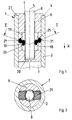
- connection end 1 and 2 show a component with at least one connection end 1, one of a Wall 2 surrounding receiving opening 3, which on an end face 4 of the component ends.
- Component e.g. from a pipe made from stable and the connection end 1 from one End of this tube.
- the tube can not in a manner known per se illustrated, the pipe end somewhat superior plastic sheathing.
- the receiving opening 3 is e.g. cylindrical and has a longitudinal axis 5 on.
- FIGS. 1 to 3 there is a device for connecting the component to another component 1 to 8 provided, one for insertion into the receiving opening 3rd certain sleeve 6 and a screwable into this, with an external thread 7th provided threaded bolt 8 contains.
- Sleeve 6 according to a first embodiment of a cylindrical sleeve, the External cross section essentially the diameter of the receiving opening 3 and its Inner diameter essentially corresponds to the diameter of the threaded bolt 8.
- the sleeve 6 is provided with at least one radial recess 18 provided in the opposite sides at least two resiliently designed, substantially parallel to the longitudinal axis 5 Leg 19.20 protrude, the ends of which face each other with a small distance.
- the exemplary embodiment is the sleeve 6 which extends through the recess 18 transversely to the longitudinal axis 5 provided, on both sides of the longitudinal axis 5 and on two diametrically opposite Place a pair of opposing legs 19, 20 protrudes.
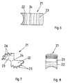
- Toothed wedges 21 are pivotally mounted, the shape of which can be seen in FIGS. 4 to 8. After that each toothed wedge has 21 end sections 22 and 23 and one arranged between them, of Both sides worked on taper or constriction 24, the concave recesses forms, in the assembly of FIGS. 1 and 2, the ends of the pairs opposite legs 19,20 are inserted so that the toothed wedges 21 in the Spaces between these can be pivoted about axes in the manner of pivot levers are stored, which are substantially perpendicular to the longitudinal axis 5.
- the toothed wedges 21 are provided on the outer sides of their end sections 22 with at least one, preferably with a plurality of first teeth 25, which serve as barbs acting opposite to the joining direction (arrow v ).
- the toothed wedges 21, on the other hand, have at least one second tooth 26, which is used for screwing in the threaded bolt 8, fits into the threads thereof and can act as an internally threaded section of the sleeve 6.
- each toothed wedge 21 is between the associated legs 19,20 arranged that the end portions 22 and first teeth 25 radially outside End sections 23 and second teeth 26, however, are located radially on the inside.
- the Arrangement made so that the maximum distance between the tips of the first and second Teeth 25,26 is slightly larger than the distance of the wall 2 from the threaded bolt 8 in assembled state corresponds, so that the teeth 25 and 26 even then something about the Sleeve 6 can protrude inwards or outwards when the toothed wedges 21 are almost radial are arranged.
- the sleeve 6 has at its axial ends a first, projecting radially outwards Stop element 27 and a second, radially inwardly projecting stop element 28.
- FIG. 3 shows, from two identical half-shells 6a and 6b, each forming a recess 18 Have recess 18a, 18b and a pair of legs projecting into this 19.20 and are separated along a separating surface which is essentially parallel to the longitudinal axis 5 runs.
- three or more shells could be used and three or more accordingly Toothed wedges 21 may be provided.
- the existing sections 18a, 18b can be hinge-like webs and possibly an adhesive tape or the like held together his.
- the device according to FIGS. 1 to 8 is used essentially as follows:
- the sleeve 6 provided with the toothed wedges 21 is inserted with the stop element 28 first into the receiving opening 3 until the stop element 27 bears against its outer end face.
- the threaded bolt 8 is then inserted into the sleeve 6 without rotating movement until it rests on the stop element 28.
- the threaded bolt 8 is moved between the second, radially inner teeth 26, which deflect resiliently in the direction of arrow v , because the toothed wedges 21 can take the resilient legs 19, 20 with them during this pivoting movement.
- the toothed wedge 21 shown on the left is pivoted clockwise in FIG.
- the threaded bolt 8 has, for example, a screw head, not shown, which can be actuated by a tool.
- a screw head not shown
- the threaded bolt 8 has, for example, a screw head, not shown, which can be actuated by a tool.
- its free end is supported on the stop element 28, while at the same time the teeth 26 enter the threads of the thread 7 of the bolt 8 and move upward in this in FIG. 1.
- the sleeve 6 out of the receiving opening 3 against the joining direction (arrow v ), ie to load it under tension.
- the barb tips of the first teeth 25, which are pressed more and more against the wall 2 of the receiving opening 3 when the threaded bolt 8 is inserted, gradually dig into the latter and thereby prevent such axial movements of the sleeve 6.
- connection end of a second component corresponding to the connection end 1 according to FIGS. 1 and 2 it would be possible to first fasten the threaded bolt 8 in a connection end of a second component corresponding to the connection end 1 according to FIGS. 1 and 2 and then to insert it only into the receiving opening 3 so far that its free end does not touch the connection element 28.
- the axial abutment required for tightening the connection is created in that the other component in FIG. 1 rests on the end face 4 or the stop element 27 from above. If the second component is then rotated, the second teeth 26 move analogously to the above description in the threads of the bolt 8 in a direction opposite to the arrow v , whereby the connection is tightened.
- connection end 1 with its Receiving opening 3 plugged onto the threaded bolt 8 and then by turning the entire component attached to this. It can either be the component with its Support the end face 4 on the wall or on the floor or the bolt 8 on the stop 28.
- the tooth wedges 21 are preferably made of a hardened steel which is harder than that Is material from which the wall 2 surrounding the receiving opening 3 is made.
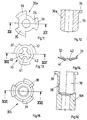
- FIGS. 9 to 22 are based on the same principle of action like the embodiment of FIGS. 1 to 8 and are explained below, wherein the same parts are provided with the same reference numerals.
- a sleeve 30 is provided, the outer diameter of which essentially corresponds to the diameter of the receiving opening 3 and the inner diameter of which essentially corresponds to the diameter of the bolt 3.
- the sleeve 30 has in a central region at least one cut-through in the form of a radial slot 31 through which a first, radial, outwardly projecting segment 32 (FIG. 10) of a loose insert, preferably made of hardened steel, is inserted Belleville spring 33 protrudes.
- the radially outer end 32a of the segment 32 is sharp-edged and acts in a direction opposite to the joining direction (arrow w in FIG. 9) analogous to the teeth 25 (FIG. 1) as a barb.
- the plate spring 33 has three segments 32, which are arranged like a segment of a circle and are spaced apart in the circumferential direction by edge cutouts 34.
- the insert 30 has three slots 31.
- Section 30a is continuous formed as a sleeve and with three radially outwardly projecting, Provide axially parallel ribs 35, which at their upper ends in FIG. 90 ° outwardly projecting lugs 36 are provided.
- the inside diameter of the sleeve corresponds essentially to the diameter of the threaded bolt 8, during the Diameter of the cylindrical surface formed by the outer surfaces of the ribs 36 in essentially corresponds to the inside diameter of the receiving opening 3.
- Section 30b in a lower part in FIGS. 15, 16 is sleeve-shaped, being Inner diameter is essentially the outer diameter of the bolt 8 and Outer diameter essentially corresponds to the diameter of the receiving opening 3.
- the upper part of this section 30b in FIG. 16, on the other hand, is through three to a longitudinal axis 37 parallel segments 38 are formed, which run along cylinder sections and in Are circumferentially spaced by an amount that the measured in the circumferential direction Corresponds to the width of the ribs 35 of the section 30a.
- the diameter of the of the Outer surfaces of the segments 38 defined cylinder surface corresponds essentially to that Diameter of the receiving opening 3.
- the inner diameter of the of the segments 38 limited hollow cylinder corresponds to the diameter measured between the ribs 35 of the section 30a, so that this in Fig. 16 axially from above into the section 30b can be inserted, the ribs 35 in the spaces between the Segments 38 occur.
- the segments 38 point radially externally projecting lugs 39, which after the introduction of the section 30a in the Section 30b come to rest between the lugs 36 and with these a first Form the stop element.
- the second stop element can in this embodiment be designed analogously to the stop element 28 (FIG. 1).
- the plate spring 33 has three segments 32 (FIGS. 10, 13, 14), which can be inserted from above into the section 30 b in such a way that the segments 32 lie in a slot between two segments 38 and the section 30 a come.
- the plate spring 33 has a center hole 40 for the threaded bolt 8, the edge of which is delimited by three tabs 41 which are formed by cutout segments 42 in the form of circular segments in the middle part of the plate spring 33.
- the tabs 41 are preferably slightly oblique in the joining direction (arrow w in FIG. 9), while the segments 32 are slightly inclined in the opposite direction.
- the diameter of the inner circle delimited by the tabs 41 is preferably somewhat smaller than the diameter of the threaded bolt 8, while the diameter of the circle formed by the outer ends of the segments 32 is preferably somewhat larger than the diameter of the receiving opening 3.
- the sleeve 30 is appropriately preassembled by first the plate spring 33 and then section 30a is inserted into section 30b. After this assembly protrude outer ends of the segments 32 of the plate spring 33 slightly over the outer circumference of the Sections 30a, 30b radially outward and the outer ends of the tabs 41 of the plate spring 33 radially inwards somewhat beyond the inner circumference of the sections 30a, 30b.
- the bottom of section 30a and the top of the sleeve-shaped Part of section 30b may be provided with conical or stepped surfaces in such a way that in the assembled state sufficiently large to pass through the segments 32 of the plate spring 33 suitable slots 31 (Fig. 9) can be obtained.
- Sections 30a, 30b after being joined by gluing or otherwise into a fixed one To connect the unit together.
- the three segments each 32 and 38, ribs 35 and flap 41 are only examples and their shape and number can also be chosen differently.
- the device according to FIGS. 9 to 16 is used analogously to the previous example in that first the sleeve 30 is inserted into the receiving opening 3 and then the bolt 8 is inserted into the sleeve 30 without rotating movement. Both the segments 32 and the tabs 41 of the plate spring 33 can yield resiliently until the arrangement according to FIG. 9 is reached.
- the tabs 41 move upward in its threads opposite to the arrow w , as a result of which the barbed outer edges 32a of the segments 32 of the plate spring 33 dig into the wall 2 and, if necessary, delimit the lower slots 31 Put on walls.
- a tight fit of the device in the receiving opening 3 is also achieved in this embodiment.
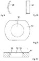
- the exemplary embodiment according to FIGS. 17 to 22 has a sleeve 44 which, analogously to FIG. 3, consists of two halves 44a, 44b (FIG. 18) which are separated along a separating surface which runs essentially parallel to the longitudinal axis 5.
- the halves 44a, 44b each have a radially outwardly projecting stop element 45 at one end and a second stop element 46 in the form of a base at the opposite end.
- a groove 47a, 47b is also formed in this bottom, which in the collapsed state of the sections 44a, 44b form a slot 47 (FIG. 17) which projects radially through the sleeve 44.
- a locking element in the form of a leaf spring 48 is inserted into the grooves 47a, 47b, the length of which is somewhat greater than the length of the grooves 47a, 47b or the slot 47, so that it protrudes somewhat laterally with its sharp-edged ends 48a which act as barbs.
- the shape of the recess or the slot 47 viewed from the stop element 45, is curved somewhat concavely, and the leaf spring 48 is correspondingly concave according to FIGS. 17, 19.
- the zones of the slot 47 adjoining the outer casing of the sleeve 44, as shown in FIGS. 17, 18, are somewhat conically widened in the axial direction.
- the ends of the leaf spring 48 can spring out in a direction opposite to the arrow x . If the sleeve 44 is then to be moved in the opposite direction of the arrow x and subjected to tension, the sharp edges of the ends 48a of the leaf spring 48 dig into the wall 3, whereby they can only deflect until they lie against the bottom of the slot 47.
- the sleeve 44 in a between the Stop elements 45,46 lying area one of recesses 49a, 49b in the Sections 44a, 44b formed cavity 49 into which one is enlarged in Fig. 21,22 shown folding nut 50 and a bias spring 51 are inserted.
- the folding nut 50 is normally arranged (Fig. 17) that the by their center hole 52 (Fig. 21,22) extending axis an angle with the longitudinal axis 5 of the Sleeve 44 forms.
- e.g. 17 has an approximately triangular shape Cross-section on, in one corner 53 (in Fig. 17 left) one side end the folding nut 50 is pivotally mounted, while a diametrically opposite one End of the folding nut 50 abuts a stop surface 54.
- Threads 55 (FIG. 22) bordering the center hole 52 are exactly coaxial in this inclined position aligned with the longitudinal axis 5 so that the threaded bolt 8 in this inclined position in the Folding nut 50 can be screwed in (Fig. 17).
- the threaded bolt 8 is to be inserted into the folding nut 50 analogously to the other exemplary embodiments without a rotary movement, it is only necessary to press it axially firmly against the latter.
- the folding nut 50 is then pivoted about the end in the corner 53 by compressing the biasing spring 51 in the direction of the arrow x , whereby the central hole 52 for the bolt 8 opens further and this can now be pushed through to the second stop element 46 without rotating movement.
- the folding nut 50 comes under the influence of the biasing spring 51 back into the position shown in FIG. 17, so that the thread of the threaded bolt 8 now engages in its threads 55 and can be rotated in this direction of rotation to the described device in the receiving opening 3rd to fix.
- the sleeve 44 according to FIGS. 17 to 22 is analogous to the others described Sleeves designed so that their outer diameter approximately the diameter of the receiving opening 3 and its inner diameter corresponds approximately to the pin diameter.
- the two sections of the sleeves 17, 30 and 44 are preferably made of plastic made by injection molding.
- the barbed parts are preferred Made of hardened steel and especially materials that are harder than that Is material from which the wall 2 of the receiving opening 3 is made. This ensures that the barbs are effective not only by clamping, but by doing so be that they penetrate into the wall material, get caught in it and only with Violence or by exerting great tensile forces and destroying the wall material the receiving opening 3 can be pulled out.
- All of the described exemplary embodiments have the advantage that they are simple and inexpensive to manufacture and easy to assemble parts and that neither to tighten the connection nor to screw the threaded bolts in for the first time the sleeves require a rotational movement of the threaded bolt. This allows the desired connections or fastenings quickly and without great assembly effort getting produced.
- the invention is not restricted to the exemplary embodiments described, which are based on can be modified in many ways. This is especially true for the shape, number and Arrangement of the different teeth and edges that act as barbs. Is further it is clear to the person skilled in the art that the devices described are analogous to EP 0 477 713 B1 also for fastening a tubular component, e.g. of a pipe, on a plate-shaped Component, e.g. can be used on a rosette. In the embodiment 9 it would be e.g.
- the sleeve 30 or its portions 30a, 30b instead of with the stop elements 36 with the sections assigned to one another on one Wall or the like attachable rosette lower part and in this Form sections of screw holes or the like for fastening screws.
- the sleeve 30 would thus be an integral part of a rosette part form.
- the devices described can also be used for connection / fastening used by other than tubular components.
Applications Claiming Priority (2)
| Application Number | Priority Date | Filing Date | Title |
|---|---|---|---|
| DE1999149695 DE19949695A1 (de) | 1999-10-15 | 1999-10-15 | Vorrichtung zum Befestigen oder Verbinden von Bauteilen |
| DE19949695 | 1999-10-15 |
Publications (2)
| Publication Number | Publication Date |
|---|---|
| EP1092881A2 true EP1092881A2 (fr) | 2001-04-18 |
| EP1092881A3 EP1092881A3 (fr) | 2002-06-12 |
Family
ID=7925731
Family Applications (1)
| Application Number | Title | Priority Date | Filing Date |
|---|---|---|---|
| EP00122516A Withdrawn EP1092881A3 (fr) | 1999-10-15 | 2000-10-14 | Dispositif de fixation ou d'assemblage d'éléments de construction |
Country Status (2)
| Country | Link |
|---|---|
| EP (1) | EP1092881A3 (fr) |
| DE (1) | DE19949695A1 (fr) |
Cited By (4)
| Publication number | Priority date | Publication date | Assignee | Title |
|---|---|---|---|---|
| KR20040009094A (ko) * | 2002-07-22 | 2004-01-31 | 이시재 | 체결력이 우수한 고정기구 |
| EP1388451A1 (fr) * | 2002-08-08 | 2004-02-11 | Dr.Ing. h.c.F. Porsche Aktiengesellschaft | Bouchon de remplissage d'huile pour moteur à combustion interne |
| WO2004106767A2 (fr) * | 2003-05-26 | 2004-12-09 | Christian Bauer Gmbh + Co. | Rondelle-ressort a deplacement bloque axialement |
| CN105736535A (zh) * | 2016-04-20 | 2016-07-06 | 龚海常 | 一种家具用的伸缩机构 |
Families Citing this family (4)
| Publication number | Priority date | Publication date | Assignee | Title |
|---|---|---|---|---|
| DE102005027281B4 (de) | 2005-06-14 | 2007-03-15 | Itw Automotive Products Gmbh & Co. Kg | Verbindungsvorrichtung zwischen einem länglichen Bauteil und einer Gewindestange |
| DE102015202593A1 (de) | 2015-02-12 | 2016-08-18 | Lamello Ag | Dübelelement, Befestigungsvorrichtung, Verfahren zur Herstellung eines Dübelelements und Verfahren zur Montage einer Befestigungsvorrichtung |
| DE102016215512A1 (de) * | 2016-08-18 | 2018-02-22 | Volkswagen Aktiengesellschaft | Befestigungsanordnung zwischen zwei Bauteilen |
| DE102019124390A1 (de) * | 2019-09-11 | 2021-03-11 | Schmitz Cargobull Aktiengesellschaft | Türverschlusseinrichtung und Nutzfahrzeugaufbau mit Türverschlusseinrichtung |
Citations (7)
| Publication number | Priority date | Publication date | Assignee | Title |
|---|---|---|---|---|
| US3208409A (en) | 1964-05-25 | 1965-09-28 | John Gale Company | Desk device |
| DE7417689U (de) | 1975-02-27 | Deutsche Tecalemit Gmbh | Rohr mit unlösbarer Steckverbindung | |
| GB1477758A (en) | 1974-06-12 | 1977-06-29 | Illinois Tool Works | Screw anchor clips |
| DE2632696A1 (de) | 1976-07-21 | 1978-01-26 | Wilke | Montagesystem |
| DE2904776C2 (fr) | 1979-02-08 | 1993-03-04 | Heinrich Wilke Gmbh, 3548 Arolsen, De | |
| EP0477713B1 (fr) | 1990-09-27 | 1994-05-04 | HEWI Heinrich Wilke GmbH | Dispositif pour fixer notamment une pièce de construction tubulaire à une paroi ou un élément similaire |
| DE4030978C2 (de) | 1990-09-27 | 1996-12-12 | Wilke Heinrich Hewi Gmbh | Verbindungseinrichtung für Rohre |
Family Cites Families (11)
| Publication number | Priority date | Publication date | Assignee | Title |
|---|---|---|---|---|
| DE117017C (fr) * | 1899-11-04 | |||
| FR912009A (fr) * | 1944-01-24 | 1946-07-26 | Liaison par écrou et vis | |
| US2528675A (en) * | 1947-01-20 | 1950-11-07 | Tinnerman Products Inc | Fastening device |
| CH281695A (de) * | 1950-05-25 | 1952-03-31 | Egli Willy | Metall-Spreizdübel. |
| FR1111686A (fr) * | 1954-09-22 | 1956-03-02 | Cheville | |
| DE1918869U (de) * | 1964-12-01 | 1965-07-01 | Artur Fischer | Duebel zur befestigung von gegenstaenden in baustoffen. |
| FR2217580B1 (fr) * | 1973-02-10 | 1978-06-02 | Molyneux Godfrey | |
| DE3201365A1 (de) * | 1981-10-06 | 1983-04-14 | Beckmann KG, 7410 Reutlingen | Vorrichtung zum verhindern einer axialbewegung eines gefuehrten rundprofilkoerpers, insbesondere eines zapfrohres an einem bierfass |
| DE8323284U1 (de) * | 1983-08-12 | 1984-01-12 | Ehlert, Marianne | Blechdübel |
| US5242252A (en) * | 1990-02-09 | 1993-09-07 | Haerle Anton | Self-locking threaded connection |
| GB9209155D0 (en) * | 1992-04-28 | 1992-06-10 | Dzus Fastener Europe | A fastening device |
-
1999
- 1999-10-15 DE DE1999149695 patent/DE19949695A1/de not_active Withdrawn
-
2000
- 2000-10-14 EP EP00122516A patent/EP1092881A3/fr not_active Withdrawn
Patent Citations (7)
| Publication number | Priority date | Publication date | Assignee | Title |
|---|---|---|---|---|
| DE7417689U (de) | 1975-02-27 | Deutsche Tecalemit Gmbh | Rohr mit unlösbarer Steckverbindung | |
| US3208409A (en) | 1964-05-25 | 1965-09-28 | John Gale Company | Desk device |
| GB1477758A (en) | 1974-06-12 | 1977-06-29 | Illinois Tool Works | Screw anchor clips |
| DE2632696A1 (de) | 1976-07-21 | 1978-01-26 | Wilke | Montagesystem |
| DE2904776C2 (fr) | 1979-02-08 | 1993-03-04 | Heinrich Wilke Gmbh, 3548 Arolsen, De | |
| EP0477713B1 (fr) | 1990-09-27 | 1994-05-04 | HEWI Heinrich Wilke GmbH | Dispositif pour fixer notamment une pièce de construction tubulaire à une paroi ou un élément similaire |
| DE4030978C2 (de) | 1990-09-27 | 1996-12-12 | Wilke Heinrich Hewi Gmbh | Verbindungseinrichtung für Rohre |
Cited By (7)
| Publication number | Priority date | Publication date | Assignee | Title |
|---|---|---|---|---|
| KR20040009094A (ko) * | 2002-07-22 | 2004-01-31 | 이시재 | 체결력이 우수한 고정기구 |
| EP1388451A1 (fr) * | 2002-08-08 | 2004-02-11 | Dr.Ing. h.c.F. Porsche Aktiengesellschaft | Bouchon de remplissage d'huile pour moteur à combustion interne |
| US7011229B2 (en) | 2002-08-08 | 2006-03-14 | Dr. Ing. H.C.F. Porsche Aktiengesellschaft | Oil filler device on an internal-combustion engine |
| WO2004106767A2 (fr) * | 2003-05-26 | 2004-12-09 | Christian Bauer Gmbh + Co. | Rondelle-ressort a deplacement bloque axialement |
| WO2004106767A3 (fr) * | 2003-05-26 | 2005-03-03 | Bauer Christian Gmbh & Co | Rondelle-ressort a deplacement bloque axialement |
| US7354032B2 (en) | 2003-05-26 | 2008-04-08 | Christian Bauer Gmbh + Co. | Plate spring, which is prevented from being axially displaced on a circular cylindrical surface of a receiving body |
| CN105736535A (zh) * | 2016-04-20 | 2016-07-06 | 龚海常 | 一种家具用的伸缩机构 |
Also Published As
| Publication number | Publication date |
|---|---|
| DE19949695A1 (de) | 2001-04-19 |
| EP1092881A3 (fr) | 2002-06-12 |
Similar Documents
| Publication | Publication Date | Title |
|---|---|---|
| EP1135616B1 (fr) | Assemblage en t de deux barreaux profiles | |
| EP2443352B1 (fr) | Système de liaison de barres profilées | |
| DE1750969B1 (de) | Verbindungsvorrichtung zur verbindung rohrfoermiger teile | |
| DE4030978C2 (de) | Verbindungseinrichtung für Rohre | |
| EP0206327B1 (fr) | Dispositif de connexion d'éléments tubulaires | |
| EP0333772B1 (fr) | Systeme modulaire de construction | |
| EP0477713B1 (fr) | Dispositif pour fixer notamment une pièce de construction tubulaire à une paroi ou un élément similaire | |
| DE10146492B4 (de) | Verbindungselement für Profile | |
| EP0501148A1 (fr) | Système d'assemblage pour deux éléments fabriqués en tube ou tige et/ou éléments ayant des jonctions | |
| CH673686A5 (fr) | ||
| DE4210488A1 (de) | Verbindungseinrichtung für ein insbesondere rohrförmiges Bauteil | |
| EP0564889A1 (fr) | Dispositif de raccordement, notamment pour une pièce de construction tubulaire | |
| EP1092881A2 (fr) | Dispositif de fixation ou d'assemblage d'éléments de construction | |
| EP0267161B1 (fr) | Dispositif de vissage | |
| DE3219520C2 (fr) | ||
| DE2832087A1 (de) | Verbindung von hohlprofilen, insbesondere zum aufbau von regalen, geruesten u.dgl. | |
| DE20312075U1 (de) | Vorrichtung mit zwei durch eine Verbindungsschraube zusammengehaltenen Hohlprofilen sowie Werkzeug dazu | |
| EP1134170B1 (fr) | Structure à assemblage modulaire pour des rayons de stockage | |
| CH687665A5 (de) | Gestellkonstruktion mit mehreren Stabelementen. | |
| DE4316808C2 (de) | Spannstück für Rohrelemente | |
| DE3429228A1 (de) | Fachwerk, insbesondere raumfachwerk aus rohrstaeben und knotenstuecken | |
| EP3406916B1 (fr) | Équerre pour profilés de support | |
| EP0267200A1 (fr) | Dispositif pour l'assemblage demontable de deux elements de construction. | |
| DE3328232C2 (de) | Raumfachwerk | |
| EP0382081B1 (fr) | Boulon pour connecter des pièces de construction à des surfaces murales |
Legal Events
| Date | Code | Title | Description |
|---|---|---|---|
| PUAI | Public reference made under article 153(3) epc to a published international application that has entered the european phase |
Free format text: ORIGINAL CODE: 0009012 |
|
| AK | Designated contracting states |
Kind code of ref document: A2 Designated state(s): AT BE CH CY DE DK ES FI FR GB GR IE IT LI LU MC NL PT SE |
|
| AX | Request for extension of the european patent |
Free format text: AL;LT;LV;MK;RO;SI |
|
| PUAL | Search report despatched |
Free format text: ORIGINAL CODE: 0009013 |
|
| AK | Designated contracting states |
Kind code of ref document: A3 Designated state(s): AT BE CH CY DE DK ES FI FR GB GR IE IT LI LU MC NL PT SE |
|
| AX | Request for extension of the european patent |
Free format text: AL;LT;LV;MK;RO;SI |
|
| RIC1 | Information provided on ipc code assigned before grant |
Free format text: 7F 16B 7/14 A, 7F 16B 2/24 B, 7F 16B 21/18 B, 7F 16B 37/08 B, 7F 16B 21/10 B, 7F 16B 39/30 B |
|
| AKX | Designation fees paid |
Designated state(s): AT BE CH CY DE DK ES FI FR GB GR IE IT LI LU MC NL PT SE |
|
| STAA | Information on the status of an ep patent application or granted ep patent |
Free format text: STATUS: THE APPLICATION IS DEEMED TO BE WITHDRAWN |
|
| 18D | Application deemed to be withdrawn |
Effective date: 20021213 |